

Datasheet QEB75-48S05, QEB75-48S05-K, QEB75-48S05-L, QEB75-48S05-M, QEB75-48S05-P Datasheet (PDUKE)
...Page 1
GENERAL SPECIFICATIONS
Efficiency See table
Isolation voltage
Input to Output
Input to Case
Output to Case
1600VDC,min
1000VDC,min
1000VDC,min
Isolation resistance
107 ohms, min
Isolation capacitance 2500 pF, ma
x
Switching frequency 270 KHz, typ
Approvals and standard IEC60950, UL60950, EN60950
Case material
A
luminum base plate
Weight (approx) 42g (1.46 oz)
MTBF Bellcore TR-NWT-000332, Tc=40 ºC , Io=80%,max 2.5 x 10
6
hrs
ENVIRONMENTAL SPECIFICATIONS
Operating base-plate temperature range (Note 4)
-40ºC to +100ºC
Over temperature protection 110ºC, ma
x
Storage temperature range
-55ºC to +125ºC
Thermal shock MIL-STD-810D
Vibration 10~55Hz, 2G, 3minutes period, 30minutes along X,Y and Z
Humidity , Max , Non-Condensing 95%
EMC CHARACTERI STI CS
Conducted emissions
EN55022 (Note 5)
EN55022 (Note 5)
Level
A
Level B
Radiated emissions
EN55022 Level A
ESD
Radiated immunity
Fast transient
Surge
Conducted immunity
EN61000-4-2
EN61000-4-3
EN1000-4-4
EN61000-4-5
EN61000-4-6
Perf. Criteria2
Perf. Criteria2
Perf. Criteria2
Perf. Criteria2
Perf. Criteria2
OUTPUT SPECIFICATIONS
Output power 75 Watts max
Voltage accuracy Full load and nominal Vin ± 1.5%
Voltage adjustability (Note1) + 10% , -20%
Minimum load
None
Line regulation LL to HL at FL ±0.2%
Load regulation No load to Full load See table
Remote Sense 10% of Vout
Ripple and noise
20MHz bandwidth (Measured
with a 1uF M/C and a 10uF T/C)
100mVp-p
Temperature coefficient
0.02% / ºC, max
Transient response
recovery time
25% load step change 200uS
Over voltage Protection
threshold(Non-latching Hiccup)
120% Vout max
Over Current Protection threshold 110% ~ 140% of Iout Rated
Short circuit protection Hiccup, automatics recovery
INPUT SPECIFICATIONS
Input voltage range 48V nominal input
36 – 75VDC
Under voltage lockout
Power up
Power down
34V typ.
32V typ.
Input filter (Note 2)
L-C type
Input surge voltage 100mS max 100VDC
Start up time
Nominal Vin and
constant resistor load
Power up
Remote ON/OFF
25mS typ
25mS typ
Remote ON/OFF (Note 3)
(Negative logic)
(Positive logic)
DC-DC ON
DC-DC OFF
DC-DC ON
DC-DC OFF
I
ON/OFF
= 1mA max
Short or 0V < Vr < 1.2V
Open or 3.5V < Vr < 15V
Open or 3.5V < Vr < 15V
Short or 0V < Vr < 1.2V
• SINGLE OUTPUT UP TO 25A
• INDUSTRY STANDAR D FOOTPRINT
• NO MINIMUM LO AD
• ADJUSTABLE OUTP U T V O LTAGE
• UNDER-VOLTAGE LOCKOUT
• HIGH EFFICIENCY UP TO 90%
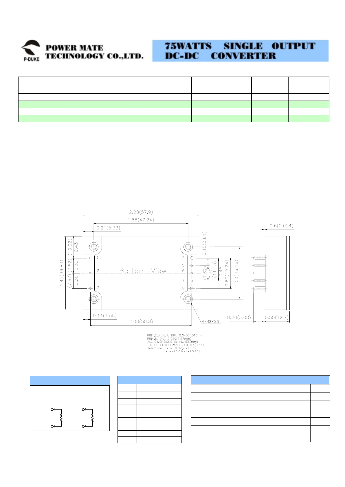
• COMPACT 2.28 X 1.45 X 0.50 INCH PACKAGE
• FIXED SWITCHING FREQUENCY
QEB75 single output DC/DC converters provide up to 75 watts of output power in an
industry standard quarter-brick package and footprint. These units are specifically
designed to meet the power needs of low-voltage silicon. All models feature a wide input
range, trimmable output voltage and a 25A current rating. Remote sense and remote
on/off facilities are included as standard, and the converters are comprehensively
protected against over-current, over-voltage and over-temperature conditions. The
QEB75 converters are especially suited to telecom, networking and industrial
application.
TECHNICAL SPECIFICATION
A
ll specification s are typical at nominal input, full load and 25ºC otherwise noted
UL E193009
TUV R50020744
CB JPTUV-5363
CE MARK
Page 2
Model
Number
Input
Range
Output
Voltage
Output
Current
Eff
(6)
(%)
Load
regulation
QEB75-48S1P8 36 – 75 VDC 1.8 VDC 25A 85 5.4mV
QEB75-48S2P5 36 – 75 VDC 2.5 VDC 25A 87 7.5mV
QEB75-48S3P3 36 – 75 VDC 3.3 VDC 20A 90 10mV
QEB75-48S05 36 – 75 VDC 5 VDC 15A 90 15mV
PRODUCT OPTI O NS TABLE
Option Suffix
Negative remote ON/OFF logic, 0.20” pin length (standard) -
Negative remote ON/OFF logic, 0.145” pin length -L
Negative remote ON/OFF logic, 0.11” pin length -K
Positive remote ON/OFF logic, 0.20” pin length -P
Positive remote ON/OFF logic, 0.145” pin length -S
Positive remote ON/OFF logic, 0.11” pin length -M
Note
1. Maximum output deviation is 10% inclusive of trim. If remote sense is not being used, the +V sense should be connected to its corresponding
+OUTPUT and likewise the –sense should be connected to its corresponding –OUTPUT.
2. An external filter capacitor is required for normal operation. The capacitor should be capable of handing 1A ripple current for 48V models. Power mate
suggest: Nippon chemi-con KMF series, 220F/100V, ESR 90m.
3. The negative / positive logic and pin length are optional ( see table ). The pin voltage is referenced to negative input.
4. Heat sink is optional and P/N7G-00297G-00307G-00317G-0032.
5. The QEB75 meets level A and level B conducted emissions only with external components connected before the input pin to the converter.
6. Typical value at nominal input voltage and full load.
7. BASEPLATE GROUNDINGBase-plate should be grounded at one of the four screw bolts prior to operation.
8. The converter is provided by basic insulation.
PIN Define
1 - INPUT
2 ON/OFF
3 + INPUT
4 - OUTPUT
5 - SENSE
6 TRIM
7 + SENSE
8 + OUTPUT
PIN CONNECTION
Output can be externally trimmed by
using the method shown below.
EXTERNAL OUTPUT TRIMMING
7
6
TRIM UP
RU
6
5
TRIM DOWN
RD
ExampleQEB75-48S3P3-P
(7)
 Loading...