

Page 1
INTEGRATED CIRCUITS
PTN2111
1:10 LVDS clock distribution device
Product Data
2001 Jun 19
Page 2
Philips Semiconductors Product Data
PTN21 111:10 LVDS clock distribution device
FEA TURES
•100 ps part-to-part skew
•35 ps output-to-output skew
•Differential design
•Meets LVDS specification for driver outputs and receiver inputs
•Reference voltage available output V
•Low voltage V
range of +2.375 V to 2.625 V
CC
BB
•High signalling rate capability (above 622 MHz)
•Supports open, short, and terminated input fail-safe (HIGH output
state)
•Programmable drivers power off control
•Available in LQFP32 package
DESCRIPTION
The PTN2111 is a low skew programmable 1:10 LVDS clock
distribution device. The selected input signal is fanned out to 10
identical differential outputs.
The PTN2111 features an 11-bit Shift Register with a serial-in and a
Control Register. The purpose of the Control Register is to enable or
power off each output clock channel and to select the clock input.
The PTN2111 is specifically designed, modeled and produced with
low skew as the key goal. Optimal design and layout serve to
minimize gate-to-gate skew within a device. The final result is a
dependable guaranteed low skew device.
The PTN2111 can be used for high performance clock distribution in
+2.5 V systems with LVDS levels. Designers can take advantage of
the device’s performance to distribute low skew clocks across the
backplane or the board.
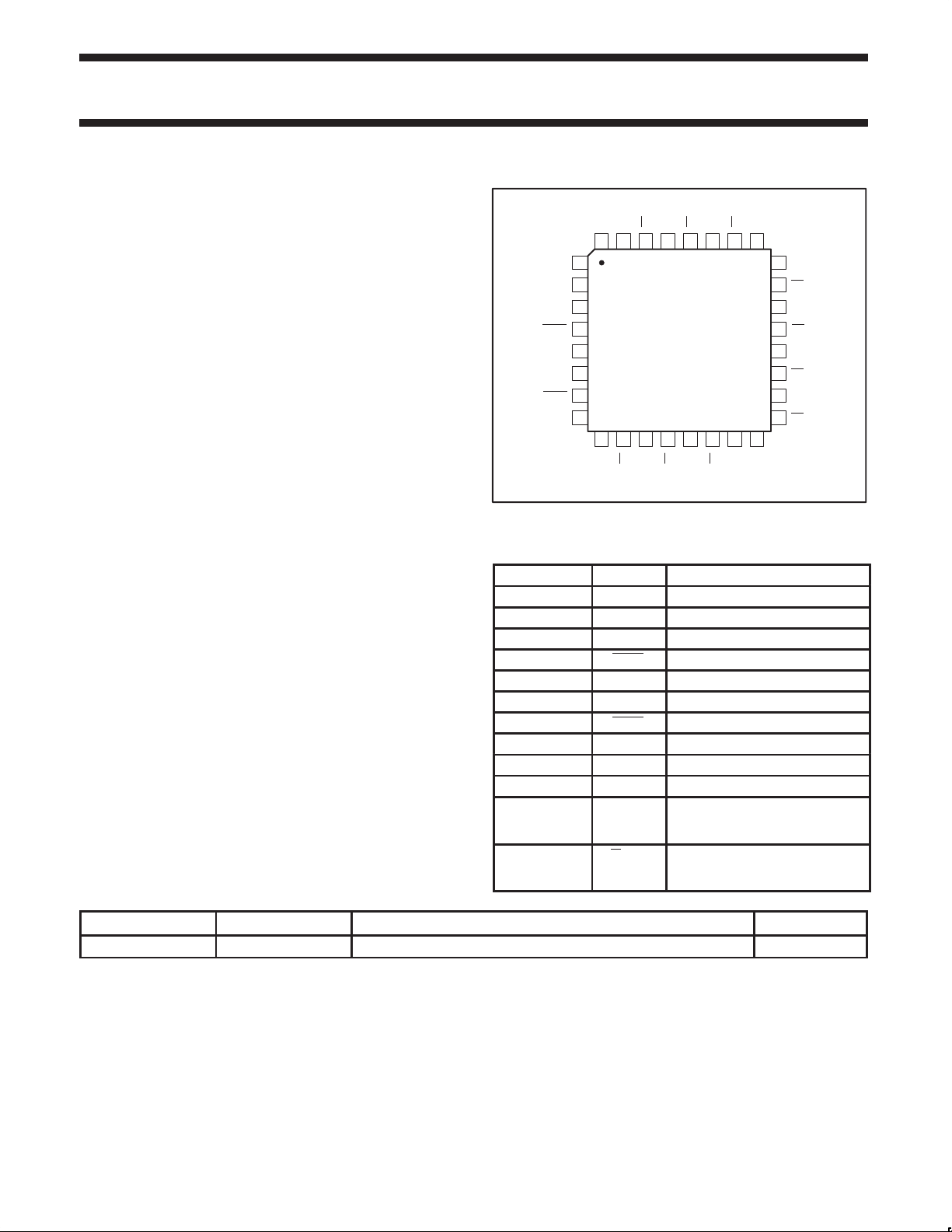
PIN CONFIGURATION
CC
Q0
Q0
Q1
Q1
Q2
Q2
27
14
Q7
26
15
Q7
GND
25
24
23
22
21
20
19
18
17 Q6
16
CC
V
ST00013
Q3
Q3
Q4
Q4
Q5
Q5
Q6
CLK0
CLK0
V
CLK1
CLK1
CK
V
32
31
30
29
28
1
2
SI
3
4
5
BB
6
7
8EN
9
11
10
12
13
Q9
Q9
Q8
GND
Q8
PIN DESCRIPTION
PIN NUMBER SYMBOL NAME AND FUNCTION
1 CK Control register clock
2 SI Control register serial-in/CLK_SEL
3 CLK0 Differential input
4 CLK0 Differential input
5 V
6 CLK1 Differential input
7 CLK1 Differential input
8 EN Device enable/program
9, 25 GND Ground
16, 32 V
31, 29, 27, 24,
Q[0:9] Differential outputs
22, 20, 18, 15,
13, 11
30, 28, 26, 23,
Q[0:9] Differential outputs
21, 19, 17, 14,
12, 10
Output reference voltage
BB
Supply voltage
CC
TYPE NUMBER NAME DESCRIPTION VERSION
PTN2111BD LQFP32 Plastic low profile quad flat package; 32 leads; body 7 x 7 x 1.4 mm SOT358-1
2001 Jun 19 853-2263 26561
2
Page 3
Philips Semiconductors Product Data
PTN21111:10 LVDS clock distribution device
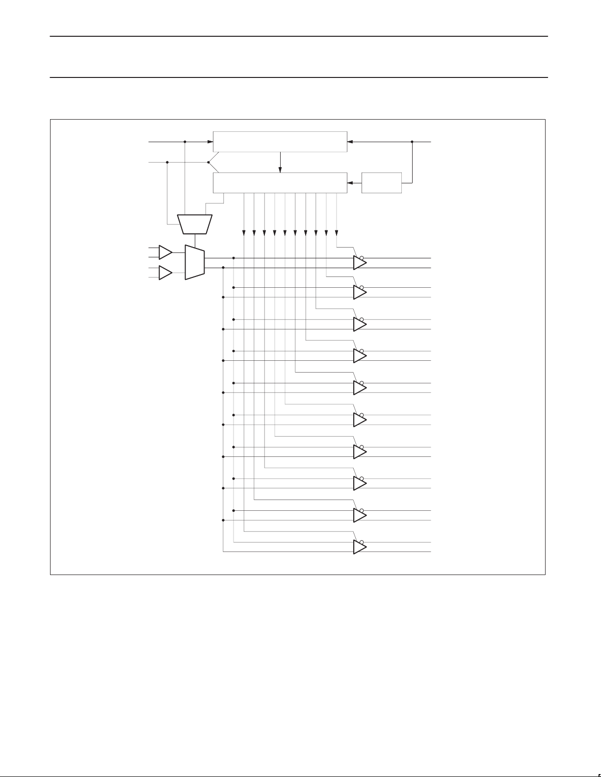
LOGIC DIAGRAM
EN
CLK0
CLK1
SI
01
SEL
0
1
Shift Register 11-Bit
Control Register 11-Bit
10
9876543210
CK
Counter
12
Q9
Q8
Q7
Q6
Q5
Q4
Q3
Q2
Q1
Q0
ST00010
2001 Jun 19
3
Page 4

Philips Semiconductors Product Data
I
Output short circuit current
IINInput current
PTN21111:10 LVDS clock distribution device
ABSOLUTE MAXIMUM RATINGS
Absolute Maximum Ratings are those values beyond which damage to the device may occur.
Functional operation under these conditions is not implied.
SYMBOL
V
I
OSD
CC
Supply voltage –0.3 to 2.8 V
Driver short circuit current continuous
ESD Electrostatic discharge (Human Body Model 1.5 kΩ, 100 pF) >2 kV
T
Junction temperature 150 °C
j
RECOMMENDED OPERATING CONDITIONS
SYMBOL PARAMETER MIN MAX UNIT
T
V
V
CC
amb
Supply voltage 2.375 2.625 V
Receiver input voltage GND V
IR
Operating ambient temperature range in free air –40 +85 °C
PARAMETER LIMITS UNIT
CC
DC ELECTRICAL CHARACTERISTICS
T
= –40 °C to +85 °C unless otherwise specified; VCC = 2.5 V ±5% (Notes 1, 2)
amb
SYMBOL
PARAMETER CONDITIONS MIN TYP
Driver
V
∆V
V
∆V
OD
OS
OSD
Output differential voltage RL = 100 Ω 250 350 450 mV
VOD magnitude change RL = 100 Ω 50 mV
OD
Offset voltage RL = 100 Ω 1.125 1.25 1.375 V
VOS magnitude change RL = 100 Ω 50 mV
OS
p
VO = 0 V 15 40 mA
VOD = 0 V 7 15 mA
Receiver
V
IDH
V
IDL
Input threshold HIGH 100 mV
Input threshold LOW –100 mV
p
VIN = 0 V 50 100 µA
VIN = V
CC
Device
V
I
C
BB
CCD
C
OUT
V
V
I
Output reference voltage
Power supply current
Input capacitance VIN = 0 V to V
IN
All drivers enabled and loaded;
Output capacitance 5 pF
Logic input HIGH threshold VCC = 2.5 V 2 V
IH
Logic input LOW threshold VCC = 2.5 V 0.8 V
IL
Logic input current
I
VCC = 2.5 V;
I
≤ 100 µA
OUT
input frequency = 800 MHz
CC
VCC = 2.5 V;
VIN = VCC or GND
1.15 1.25 1.35 V
NOTES:
1. All currents into device pins are positive; all currents out of device pins are negative. All voltages are referenced to device ground unless
otherwise specified.
2. All typical values are given for V
includes probe and fixture capacitance.
3. C
L
4. Generator waveforms for all tests unless otherwise specified: f = 1 MHz, Z
= +2.5 V and T
CC
5. The PTN2111 is a current mode device, and only functions to datasheet specifications when a resistive load is applied to the drives outputs.
= +25 °C, unless otherwise specified.
amb
= 50 Ω, 50% duty cycle.
O
2
MAX UNIT
50 100 µA
190 230 mA
5 pF
±10 µA
2001 Jun 19
4
Page 5

Philips Semiconductors Product Data
PTN21111:10 LVDS clock distribution device
AC ELECTRICAL CHARACTERISTICS (L VDS)
T
= –40 °C to +85 °C unless otherwise specified; VCC = 2.5 V ±5% (Note 1)
amb
SYMBOL
t
TLH
t
THL
t
PLH
t
PHL
f
MAX
Transition time LOW to HIGH RL = 100 Ω; CL = 5 pF 460 560 ps
Transition time HIGH to LOW RL = 100 Ω; CL = 5 pF 460 560 ps
Propagation delay to output 2 ns
Maximum input frequency 650 800 MHz
Within-device skew 35 ps
t
skew
Part-to-part skew 100 ps
Pulse skew 50 ps
NOTE:
1. Generator waveforms for all tests unless otherwise specified: f = 1 MHz, Z
PARAMETER CONDITIONS MIN TYP MAX UNIT
= 50 Ω, 50% duty cycle.
O
2001 Jun 19
5
Page 6

Philips Semiconductors Product Data
PTN21111:10 LVDS clock distribution device
CONTROL REGISTER SPECIFICA TION
The PTN2111 is provided with an 11-bit shift register with a serial-in
and a Control Register. The purpose is to enable or power-off each
output clock channel and to select the clock input. The PTN2111
provides two working modes: Programmed mode, and Standard
mode.
Programmed Mode (EN = 1)
The shift register has a serial input to load the working configuration.
Once the configuration is loaded with 11 clock pulses, another clock
pulse loads the configuration into the Control Register. To restart the
configuration of the shift register , a reset of the state machine must
be done with a clock pulse on CK, and the EN set to LOW. The
Control Register can be configured only one time after each reset.
D0 is the first bit shifted in, D10 is the last bit shifted in. Bit D0
controls Q9, D9 controls Q0, and D10 controls CLKIN.
Standard Mode (EN = 0)
In Standard Mode, the PTN2111 is not programmable. All clock
buffer outputs are enabled. The LVDS clock input is selected from
Clock0 or Clock1 with the SI pin, as shown in the Truth Table.
Table 1. Truth Table of State Machine Inputs
EN SI CK OUTPUT
L L X All outputs enabled,
Clock0 selected,
Control Register disabled.
L H X All outputs enabled,
Clock1 selected,
Control Register disabled.
H L First stage stores “L”, other
stages store the data of
previous stage.
H H First stage stores “H”, other
stages store the data of
previous stage.
L X Reset of the state machine,
Shift register, and Control
Register.
Table 2. Configuration of the Control Register
Control Register bit D0 D1 D2 D3 D4 D5 D6 D7 D8 D9 D10
Function Q9 Q8 Q7 Q6 Q5 Q4 Q3 Q2 Q1 Q0 CLK_SEL
Table 3. Truth Table of the Control Register
D10 Dn[0:9] Qn[0:9]
L H Clock0
H H Clock1
X L Qn output disabled
X = Don’t Care
AC ELECTRICAL CHARACTERISTICS (Control Register)
SYMBOL PARAMETER CONDITIONS MIN TYP MAX UNIT
f
MAX
t
t
t
rem
t
2001 Jun 19
Maximum frequency of shift register 50 MHz
Clock to SI setup time 4.0 ns
s
Clock to SI hold time 1.0 ns
h
Enable to clock removal time 4.0 ns
Minimum clock pulse width 5 ns
w
6
Page 7

Philips Semiconductors Product Data
PTN21111:10 LVDS clock distribution device
LQFP32: plastic low profile quad flat package; 32 leads; body 7 x 7 x 1.4 mm SOT358-1
2001 Jun 19
7
Page 8

Philips Semiconductors Product Data
PTN21111:10 LVDS clock distribution device
Data sheet status
Product
Data sheet status
Objective data
Preliminary data
Product data
[1] Please consult the most recently issued datasheet before initiating or completing a design.
[2] The product status of the device(s) described in this data sheet may have changed since this data sheet was published. The latest information is available on
the Internet at URL http://www.semiconductors.philips.com.
[1]
status
Development
Qualification
Production
[2]
Definitions
This data sheet contains data from the objective specification for product development.
Philips Semiconductors reserves the right to change the specification in any manner without notice.
This data sheet contains data from the preliminary specification. Supplementary data will be
published at a later date. Philips Semiconductors reserves the right to change the specification
without notice, in order to improve the design and supply the best possible product.
This data sheet contains data from the product specification. Philips Semiconductors reserves the
right to make changes at any time in order to improve the design, manufacturing and supply.
Changes will be communicated according to the Customer Product/Process Change Notification
(CPCN) procedure SNW-SQ-650A.
Definitions
Short-form specification — The data in a short-form specification is extracted from a full data sheet with the same type number and title. For
detailed information see the relevant data sheet or data handbook.
Limiting values definition — Limiting values given are in accordance with the Absolute Maximum Rating System (IEC 134). Stress above one
or more of the limiting values may cause permanent damage to the device. These are stress ratings only and operation of the device at these or
at any other conditions above those given in the Characteristics sections of the specification is not implied. Exposure to limiting values for extended
periods may affect device reliability.
Application information — Applications that are described herein for any of these products are for illustrative purposes only. Philips
Semiconductors make no representation or warranty that such applications will be suitable for the specified use without further testing or
modification.
Disclaimers
Life support — These products are not designed for use in life support appliances, devices or systems where malfunction of these products can
reasonably be expected to result in personal injury . Philips Semiconductors customers using or selling these products for use in such applications
do so at their own risk and agree to fully indemnify Philips Semiconductors for any damages resulting from such application.
Right to make changes — Philips Semiconductors reserves the right to make changes, without notice, in the products, including circuits, standard
cells, and/or software, described or contained herein in order to improve design and/or performance. Philips Semiconductors assumes no
responsibility or liability for the use of any of these products, conveys no license or title under any patent, copyright, or mask work right to these
products, and makes no representations or warranties that these products are free from patent, copyright, or mask work right infringement, unless
otherwise specified.
Philips Semiconductors
811 East Arques Avenue
P.O. Box 3409
Sunnyvale, California 94088–3409
Telephone 800-234-7381
Copyright Philips Electronics North America Corporation 2001
All rights reserved. Printed in U.S.A.
Date of release: 06-01
Document order number: 9397 750 08325
2001 Jun 19
8
 Loading...