

Page 1
PSD03
1
2
05118
Only One Name Means ProTek’Tion™
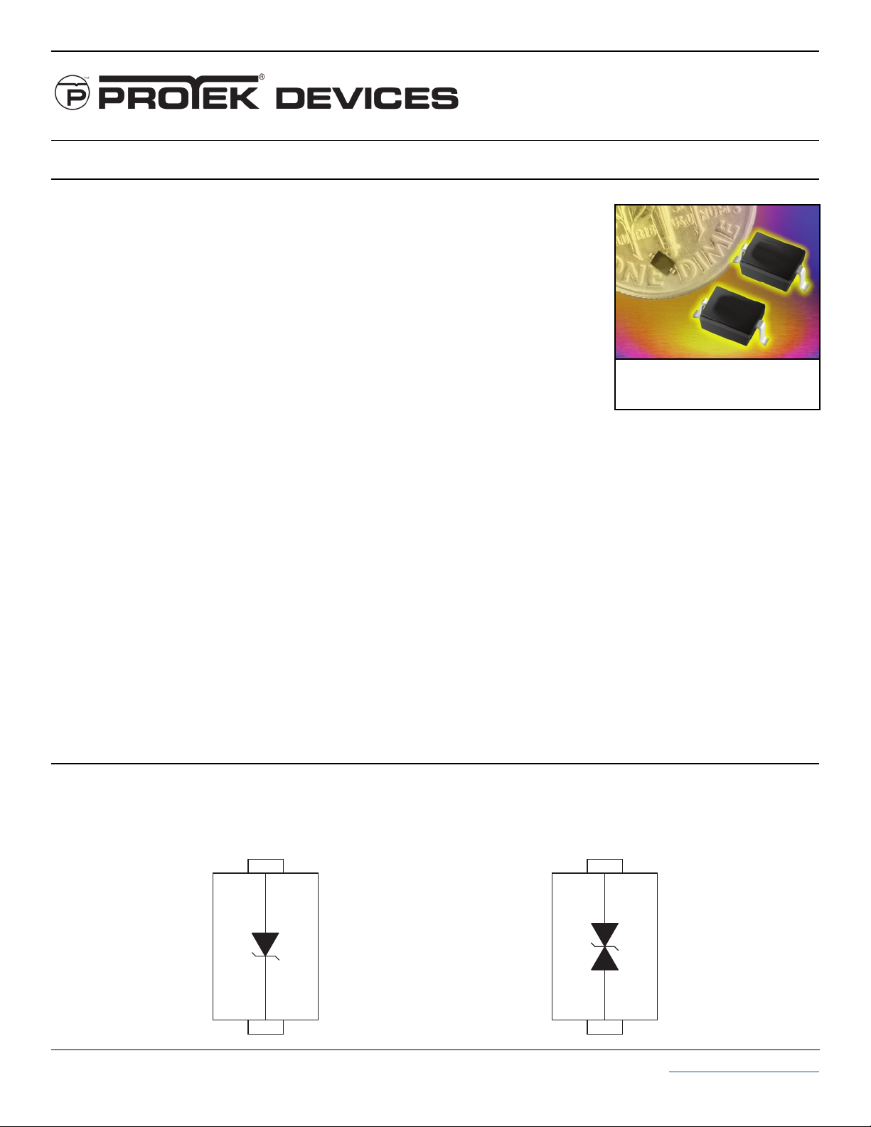
STANDARD CAPACITANCE TVS ARRAY
APPLICATIONS
✔ Laptop Computers
✔ Cellular Phones
✔ Digital Cameras
✔ Personnal Digital Assistant (PDA)
IEC COMPATIBILITY (EN61000-4)
✔ 61000-4-2 (ESD): Air - 15kV, Contact - 8kV
✔ 61000-4-4 (EFT): 40A - 5/50ns
✔ 61000-4-5 (Surge): 24A, 8/20µs - Level 2(Line-Ground) & Level 3(Line-Line)
FEATURES
✔ Unidirectional: 500 Watts Peak Pulse Power per Line (tp = 8/20µs)
✔ BidirectionalL 400 Watts Peak Pulse Power per Line (tp = 8/20µs)
✔ Unidirectional & Bidirectional Configurations
✔ Replacement for MLV (0805)
✔ Protects One Power or I/O Port
✔ ESD Protection > 40 kilovolts
✔ Low Clamping Voltage
✔ Available in Multiple Voltage Types Ranging from 3V to 36V
thru
PSD36C
SOD-323
MECHANICAL CHARACTERISTICS
✔ Molded JEDEC SOD-323
✔ Weight 10 milligrams (Approximate)
✔ Flammability Rating UL 94V-0
✔ 8mm Tape and Reel Per EIA Standard 481
✔ Device Marking: Marking Code & Polarity Band
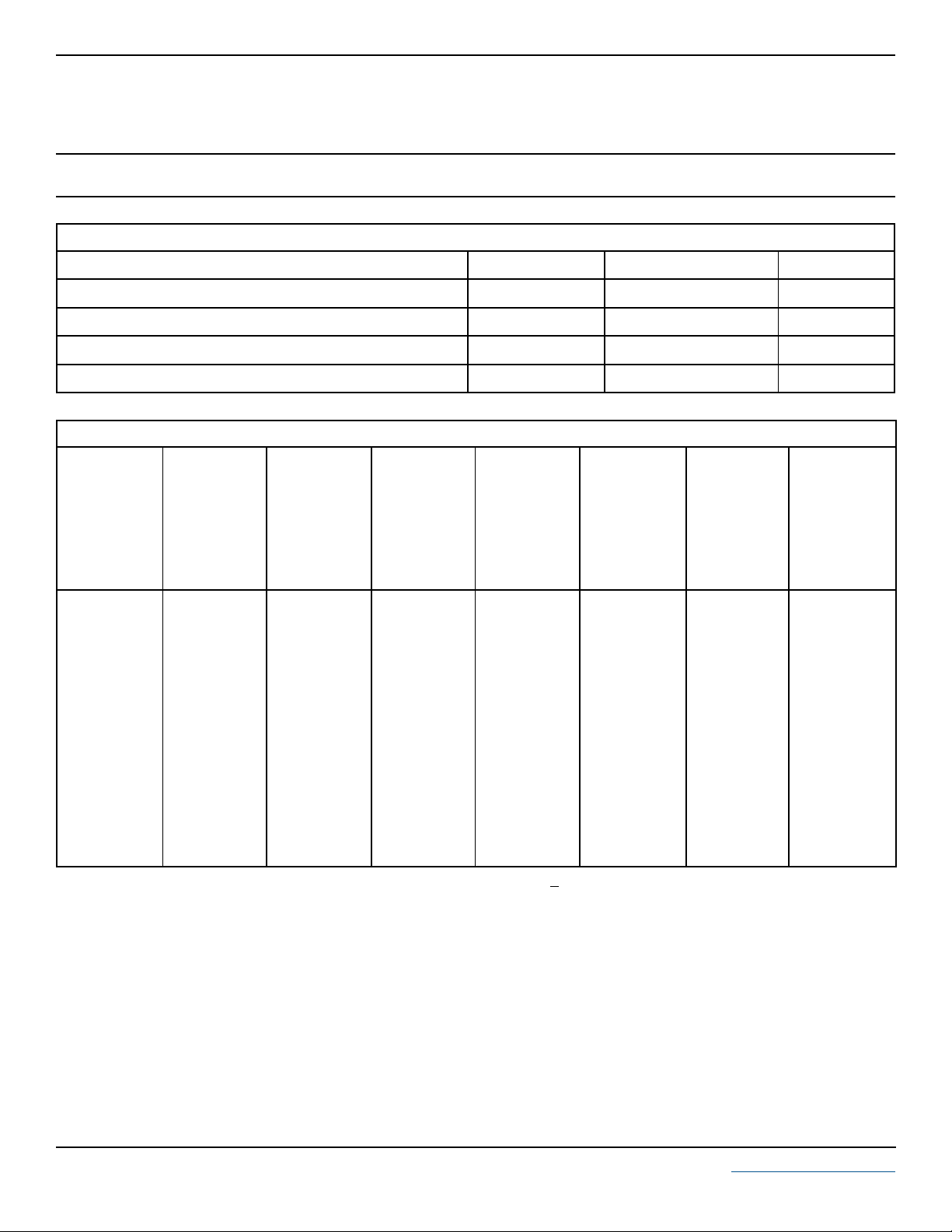
PIN CONFIGURATIONS
UNIDIRECTIONAL
(Unidirectional Only)
1
2
BIDIRECTIONAL
105118.R5 10/03 www.protekdevices.com
Page 2
DEVICE CHARACTERISTICS
MAXIMUM RATINGS @ 25°C Unless Otherwise Specified
PSD03
thru
PSD36C
PARAMETER
Undirectional: Peak Pulse Power (tp = 8/20µs) - See Fig. 1
Bidirectional: Peak Pulse Power (tp = 8/20µs) - See Fig. 1 Watts400P
Operating Temperature
Storage Temperature
SYMBOL VALUE
P
PP
PP
T
J
T
STG
500
-55°C to 150°C
ELECTRICAL CHARACTERISTICS PER LINE @ 25°C Unless Otherwise Specified
PA RT
NUMBER
DEVICE
MARKING
(See Notes 1-2)
PSD03
PSD03C
PSD05
PSD05C
PSD08
PSD08C
PSD12
PSD12C
PSD15
PSD15C
PSD18
PSD18C
PSD24
PSD24C
PSD36
PSD36C
Note 1: Part numbers with an additional “C” suffix are bidirectional devices, i.e., PSD05C.
Note 2:
For Bidirectional Devices Only:
A
G
B
H
C
J
D
K
E
L
G
N
F
M
R
T
RATED
STAND-OFF
VOLTAGE
MINIMUM
BREAKDOWN
VOLTAGE
MAXIMUM
CLAMPING
VOLTAGE
(See Fig. 2)
= 1A
@ 1mA
V
WM
VOLTS
3.3
3.3
5.0
5.0
8.0
8.0
12.0
12.0
15.0
15.0
18.0
18.0
24.0
24.0
36.0
36.0
Electrical characteristics apply in both directions.
V
(BR)
VOLTS
4.0
4.0
6.0
6.0
8.5
8.5
13.3
13.3
16.7
16.7
20.0
20.0
26.7
26.7
40.0
40.0
@ I
P
V
VOLTS
6.5
7.0
9.8
9.8
13.4
13.4
19.0
19.0
24.0
24.0
29.0
29.0
43.0
43.0
60.0
60.0
C
MAXIMUM
CLAMPING
VOLTAGE
(See Fig. 2)
@8/20µs
VC @ I
PP
10.9V @ 43.0A
10.9V @ 39.0A
13.5V @ 42.0A
14.5V @ 28.0A
16.9V @ 34.0A
18.5V @ 17.0A
25.9V @ 21.0A
29.5V @ 14.0A
30.0V @ 17.0A
33.0V @ 12.0A
40.0V @ 9.0A
40.0V @ 9.0A
49.0V @ 12.0A
46.2V @ 9.0A
75.0V @ 5.0A
75.0V @ 5.0A
MAXIMUM
LEAKAGE
CURRENT
@V
I
D
µA
125
125
10
10
10
10
1
1
1
1
1
1
1
1
1
1
WM
UNITS
Watts
°C-55°C to 150°C
°C
TYPICAL
CAPACITANCE
@0V, 1 MHz
C
J
pF
500
200
350
175
250
150
150
50
100
40
90
40
88
40
75
35
2 www.protekdevices.com05118.R5 10/03
Page 3

GRAPHS
PSD03
thru
PSD36C
PEAK PULSE POWER VS PULSE TIME
FIGURE 1
10,000
1,000
400W, 8/20µs Waveform
100
- Peak Pulse Current - Watts
PP
P
10
0.01 1 10 100 1,000 10,000
td - Pulse Duration - µs
500W, 8/20µs Waveform
FIGURE 3
POWER DERATING CURVE
100
80
60
40
% Of Rated Power
20
0
0 25 50 75 100 125 150
TL - Lead Temperature - °C
Peak Pulse Power
8/20µs
Average Power
FIGURE 2
120
PP
100
80
60
40
- Peak Pulse Current - % of I
20
PP
I
0
0 5 10 15 20 25 30
PULSE WAVE FORM
t
f
Peak Value I
-t
e
td = t
t - Time - µs
PP
IPP/2
FIGURE 4
OVERSHOOT & CLAMPING VOLTAGE FOR PSD03
35
25
15
5 Volts per Division
5
-5
ESD Test Pulse: 25 kilovolt, 1/30ns (waveform)
TEST
WAVEFORM
PARAMETERS
t
= 8µs
f
td = 20µs
400
300
200
C - Capacitance - pF
100
TYPICAL REVERSE VOLTAGE VS CAPACITANCE FOR PSD05
0
0 1 2 3 4 5 6
V
- Reverse Voltage - Volts
R
3 www.protekdevices.com05118.R5 10/03
FIGURE 5
Page 4

PACKAGE OUTLINE & DIMENSIONS
PSD03
thru
PSD36C
E
F
0.031” (0.80mm)
PACKAGE OUTLINE
C
A
B
D
MOUNTING PAD
0.118” (3.00mm)
H
0.031” (0.80mm)
SOD-323 PACKAGE
PACKAGE DIMENSIONS
0.063
0.045
0.094
0.036
0.010
0.004
-
INCHES
0.075
0.057
0.106
0.043
0.016
0.008
0.004
MILLIMETERS
DIM MIN
A
B
C
D
E
F
H
NOTES
1. Controlling Dimensions in Millimeters.
2. Dimensions are exclusive of mold flash and metal burrs.
TAPE & REEL ORDERING NOMENCLATURE
1. Surface mount product is taped and reeled in accordance
with EIA-481.
2. Suffix -T7 = 7 Inch Reel - 3,000 pieces per 8mm tape,
i.e.,
1.60
1.15
2.39
0.92
0.25
0.10
-
PSD05C-T7.
MAX MIN MAX
1.90
1.45
2.70
1.10
0.40
0.20
0.10
Outline & Dimensions: Rev 1 - 11/01, 06010
COPYRIGHT © ProTek Devices 2003
SPECIFICATIONS: ProTek reserves the right to change the electrical and or mechanical
characteristics described herein without notice (except JEDEC).
DESIGN CHANGES: ProTek reserves the right to discontinue product lines without notice, and that
the final judgement concerning selection and specifications is the buyer’s and that in furnishing
engineering and technical assistance, ProTek assumes no responsibility with respect to the
selection or specifications of such products.
ProTek Devices
2929 South Fair Lane, Tempe, AZ 85282
Tel: 602-431-8101 Fax: 602-431-2288
E-Mail: sales@protekdevices.com
Web Site: www.protekdevices.com
4 www.protekdevices.com05118.R5 10/03
 Loading...