

Page 1
PS21661-RZ/-FR
Powerex, Inc., 200 E. Hillis Street, Youngwood, Pennsylvania 15697-1800 (724) 925-7272
A
D
(2 PLACES)
K
J
H
G
E
V
F
1325476981110 1312 1514 1716 1918 2120 22 23 24 2927 2825 26
1 N
2 P
3 FO
4 NC
5 VNC
6 CIN
PS21661-RZ
US
7 VN1
8 NC
9 WN
10 VWFB
11 WP
WPG
12 W(VWFS)
M
L
N
P
303132333435
AA
AL
AB
T
QR
HEATSINK SIDE
TERMINAL CODE
UPG
25 UN
26 VUFB
27 UP
28 U(VUFS)
29 NC
30 NC
13 NC
14 NC
15 VN1
16 NC
17 VN
18 VVFBV
VPG
19 VP
20 V(VVFS)
21 NC
22 NC
23 VN1
24 NC
HEATSINK SIDE
C
Y
AK AJ
AD
AG
31 NC
32 NC
33 NC
34 NC
35 NC
W
X
B
Z
AC
AH
AFAE
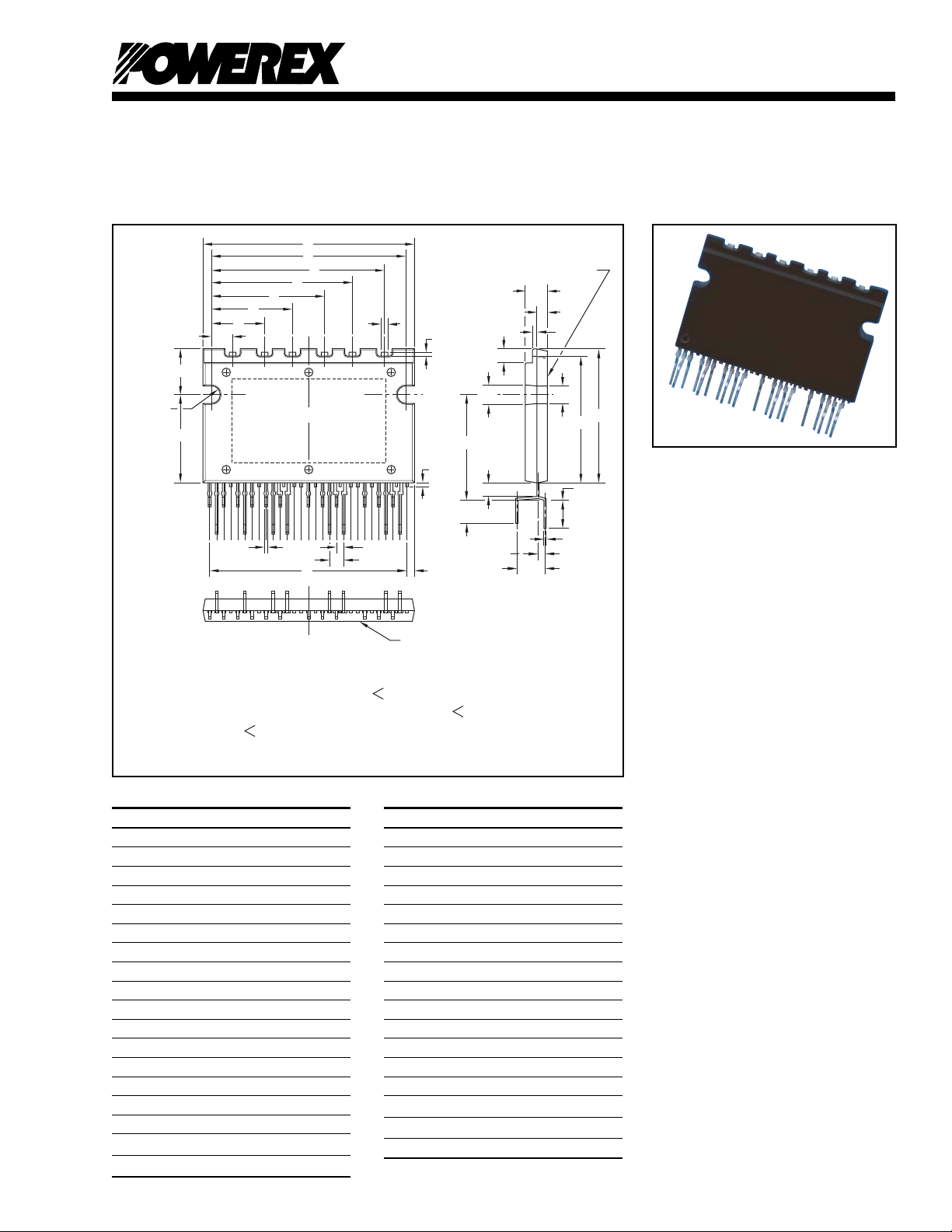
Outline Drawing and Circuit Diagram
Dimensions Inches Millimeters
A 1.50 38.0
B 0.94 24.0
C 0.16 4.0
D 1.38 35.0
E 0.33 8.5
F 0.61 15.5
G 0.15 3.8
H 0.38 9.6
J 0.57 14.6
K 0.80 20.4
L 1.00 25.4
M 1.23 31.2
N 0.047 1.2
P 0.028 0.7
Q 1.39 35.28
R 0.048 1.22
S 0.05 1.27
Dimensions Inches Millimeters
U 0.02 0.5
V 0.06 1.6
W 0.07 1.9
X 0.03 0.8
Y 0.11 2.7
Z 0.90 22.8
AA 0.75 19.0
AB 0.17 4.2
AC 0.20 5.2
AD 0.09 2.4
AE 0.15 3.81
AF 0.05 1.27
AG 0.20 5.08
AH 0.016 0.4
AJ 0.13 3.3
AK 0.14 3.6
AL 0.28 0.7
T 0.10 2.54
Intellimod™ Module
Single-In-Line Intelligent
Power Module
3 Amperes/600 Volts
Description:
SIP-IPMs are intelligent power
modules that integrate power
devices, drivers, and protection
circuitry in an ultra compact
single-in-line transfer-mold
package for use in driving small
three phase motors. Use of 5th
generation IGBTs, SIP packaging,
and application specific HVICs
allow the designer to reduce
inverter size and overall design
time.
Features:
□ Compact Packages
□ Single Power Supply
□ Integrated HVICs
□ Direct Connection to CPU
Applications:
□ Washing Machines
□ Refrigerators
□ Air Conditioners
□ Small Servo Motors
□ Small Motor Control
Ordering Information:
PS21661-RZ is a 600V,
3 Ampere SIP Intelligent
Power Module.
1
Page 2
Powerex, Inc., 200 E. Hillis Street, Youngwood, Pennsylvania 15697-1800 (724) 925-7272
PS21661-RZ/-FR
Intellimod™ Module
Single-In-Line Intelligent Power Module
3 Amperes/600 Volts
A
D
M
L
K
J
(2 PLACES)
H
G
E
V
F
PS21661-FR
N
P
303132333435
AA
AG
HEATSINK SIDE
C
Y
AH
W
X
B
Z
1325476981110 1312 1514 1716 1918 2120 22 23 24 2927 2825 26
US
QR
WPG
7 VN1
8 NC
9 WN
10 VWFB
11 WP
12 W(VWFS)
13 NC
14 NC
15 VN1
16 NC
17 VN
18 VVFBV
1 N
2 P
3 FO
4 NC
5 VNC
6 CIN
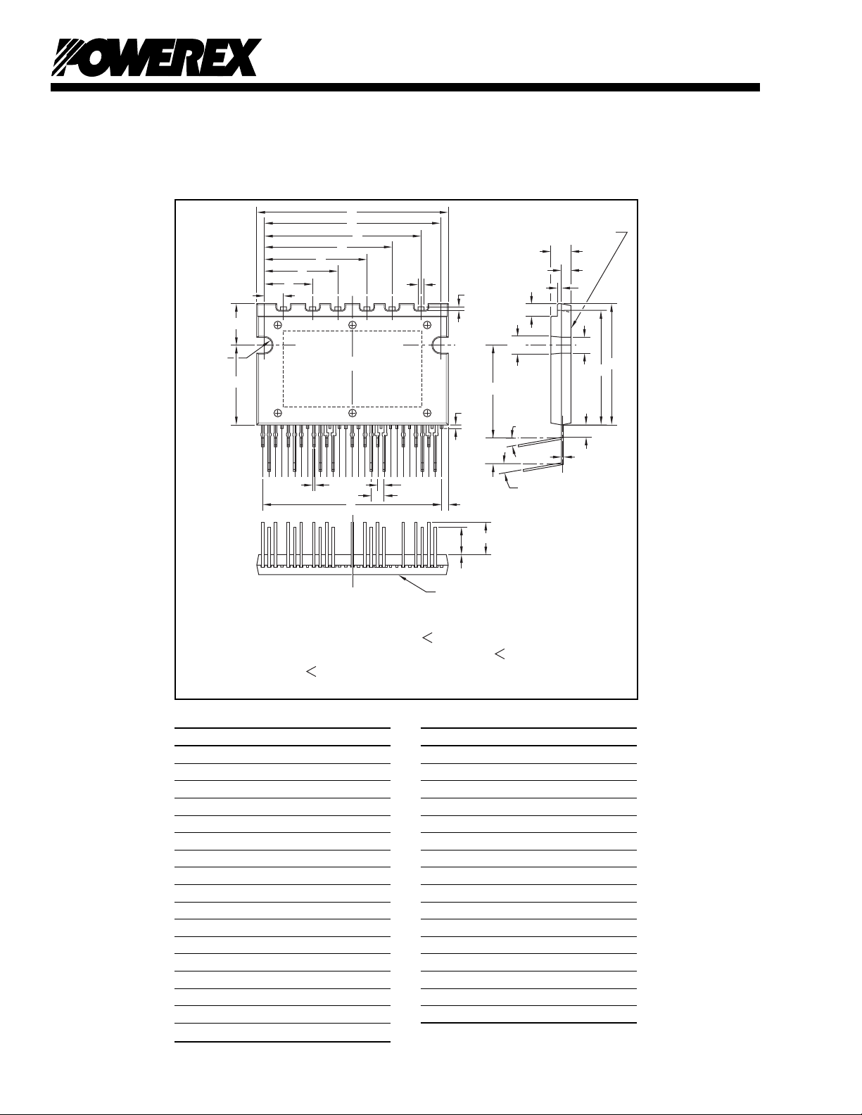
Outline Drawing and Circuit Diagram
Dimensions Inches Millimeters
A 1.50 38.0
B 0.94 24.0
C 0.16 4.0
D 1.38 35.0
E 0.33 8.5
F 0.61 15.5
G 0.15 3.8
H 0.38 9.6
J 0.57 14.6
K 0.80 20.4
L 1.00 25.4
M 1.23 31.2
N 0.047 1.2
P 0.028 0.7
Q 1.39 35.28
R 0.048 1.22
S 0.05 1.27
T
TERMINAL CODE
VPG
Dimensions Inches Millimeters
AJ
AF
AE
HEATSINK SIDE
19 VP
20 V(VVFS)
21 NC
22 NC
23 VN1
24 NC
UPG
AB
+10°
0°
-0°
+10°
0°
-0°
25 UN
26 VUFB
27 UP
28 U(VUFS)
29 NC
30 NC
31 NC
32 NC
33 NC
34 NC
35 NC
AD
AC
T 0.10 2.54
U 0.02 0.5
V 0.06 1.6
W 0.07 1.9
X 0.03 0.8
Y 0.11 2.7
Z 0.90 22.8
AA 0.71 18.1
AB 0.20 5.08
AC 0.016 0.4
AD 0.09 2.4
AE 0.22 5.5
AF 0.26 6.5
AG 0.14 3.6
AH 0.13 3.3
AJ 0.028 0.7
2
Page 3

Powerex, Inc., 200 E. Hillis Street, Youngwood, Pennsylvania 15697-1800 (724) 925-7272
PS21661-RZ/-FR
Intellimod™ Module
Single-In-Line Intelligent Power Module
3 Amperes/600 Volts
Absolute Maximum Ratings, Tj = 25°C unless otherwise specified
Characteristics Symbol PS21661-RZ/-FR Units
Power Device Junction Temperature* T
Heatsink Operation Temperature (See Tf Measurement Point Illustration) T
Storage Temperature T
j
f
stg
-20 to 125 °C
-20 to 100 °C
-40 to 125 °C
Mounting Torque, M3 Mounting Screws — 7 in-lb
Module Weight (T ypical) — 10 Grams
Self-protection Supply Voltage Limit (Short Circuit Protection Capability)** V
Isolation Voltage, AC 1 minute, 60Hz Sinusoidal, Connection Pins to Heatsink Plate V
*The maximum junction temperature rating of the power chips integrated within the SIP-IPM is 150°C (@Tf ≤ 100°C). However, to ensure safe operation of the SIP-IPM,
the average junction temperature should be limited to T
**VD = 13.5 ~ 16.5V, Inverter Part, Tj = 125°C, Non-repetitive, Less than 2µs
≤ 125°C (@Tf ≤ 100°C).
j(avg)
CC(prot.)
ISO
400 Volts
2500 Volts
IGBT Inverter Sector
Collector-Emitter Voltage V
Collector Current (Tf = 25°C) ±I
Peak Collector Current (Tf = 25°C, tw ≤ 1ms) ±I
Supply Voltage (Applied between P - N) V
Supply Voltage, Surge (Applied between P - N) V
CC(surge)
Collector Dissipation (Tf = 25°C, per 1 Chip) P
CES
C
CP
CC
C
600 Volts
3 Amperes
6 Amperes
450 Volts
500 Volts
11.1 Watts
Control Sector
Supply Voltage (Applied between VN1-VNC)V
Supply Voltage (Applied between V
UFB
-U(V
UFS), VVFB
-V(V
VFS
), V
WFB
-W(V
WFS
)) V
Input Voltage (Applied between UP, VP, WP-VNC, UN, VN, WN-VNC)V
Fault Output Supply Voltage (Applied between FO-VNC)V
Fault Output Current (Sink Current at FO Ter minal) I
Current Sensing Input Voltage (Applied between CIN-VNC)V
D
DB
IN
FO
FO
SC
Tf Measurement Point
CONTROL TERMINALS
SIP-IPM
10.5mm
FWDi CHIP
MEASUREMENT POINT
(INSIDE THE Al BOARD)
15mm
IGBT CHIP
TEMPERATURE
25mm
Al BOARD
TEMPERATURE
MEASUREMENT POINT
(INSIDE THE Al BOARD)
1.5mm
20 Volts
20 Volts
-0.5 ~ V
D
-0.5 ~ V
D
10 mA
-0.5 ~ V
D
10mm
Volts
Volts
Volts
3
Page 4

Powerex, Inc., 200 E. Hillis Street, Youngwood, Pennsylvania 15697-1800 (724) 925-7272
PS21661-RZ/-FR
Intellimod™ Module
Single-In-Line Intelligent Power Module
3 Amperes/600 Volts
Electrical and Mechanical Characteristics, Tj = 25°C unless otherwise specified
Characteristics Symbol Test Conditions Min. Typ. Max. Units
IGBT Inverter Sector
Collector Cutoff Current I
Diode Forward Voltage V
Collector-Emitter Saturation Voltage V
Inductive Load Switching Times t
CES
EC
CE(sat)IC
IC = 3A, Tj = 125°C, VD = VDB = 15V, VIN = 5V — 1.70 2.30 Volts
on
t
rr
t
C(on)
t
off
t
C(off)
= 3A, Tj = 25°C, VD = VDB = 15V, VIN = 5V — 1.60 2.15 Volts
VCE = V
VCE = V
, Tj = 25°C——1.0 mA
CES
, Tj = 125°C——10mA
CES
Tj = 25°C, -IC = 3A, VIN = 0V — 1.55 2.00 Volts
0.50 0.85 1.25 µS
VCC = 300V, VD = VDB = 15V, — 0.20 — µS
IC = 3A, Tj = 125°C, VIN = 0 ⇔ 5V, — 0.35 0.55 µS
Inductive Load (Upper-Lower Arm) — 1.00 1.50 µS
— 0.55 1.10 µS
Thermal Characteristics
Characteristic Symbol Condition Min. Typ. Max. Units
Junction to Fin R
Thermal Resistance R
th(j-f)Q
th(j-f)D
IGBT Part (Per 1/6 Module) — — 9.0 °C/Watt
FWDi Part (Per 1/6 Module) — — 9.0 °C/Watt
Recommended Conditions for Use
Characteristic Symbol Condition Min. Typ. Value Units
Supply Voltage V
Control Supply Voltage V
CC
D
V
DB
V
Control Supply Variation ∆VD, ∆V
PWM Input Frequency f
Allowable RMS Current* I
VNC Terminal Voltage V
PWM
O
NC
DB
Applied between VNC-N (Include Surge Voltage) -5 — 5 Volts
Minimum Input Pulse Width** PWIN ON/OFF 0.3 — — µS
Arm Shoot-through Blocking Time t
* The allowable RMS current value depends on the actual application conditions.
**There might be no output when the input signal width is less than PWIN.
DEAD
Applied between P-N Terminals 0 300 400 Volts
Applied between VN1-V
NC
13.5 15.0 16.5 Volts
Applied between 13.0 15.0 18.5 Volts
UFB
-U(V
UFS
), V
VFB
-V(V
VFS
), V
WFB
-W(V
WFS
)
-1 — 1 V/µs
Tf ≤ 100°C, Tj ≤ 125°C—15—kHz
VCC = 300V, VD = 15V, fc = 15kHz, — — 17 Arms
PF = 0.8 Sinusoidal, Tj ≤ 125°C, Tf ≤ 100°C
For Each Input Signal 1.5 — — µS
4
Page 5

Powerex, Inc., 200 E. Hillis Street, Youngwood, Pennsylvania 15697-1800 (724) 925-7272
PS21661-RZ/-FR
Intellimod™ Module
Single-In-Line Intelligent Power Module
3 Amperes/600 Volts
Electrical and Mechanical Characteristics, Tj = 25°C unless otherwise specified
Characteristics Symbol Test Conditions Min. Typ. Max. Units
Control Sector
Supply Voltage V
Circuit Current I
Fault Output Voltage V
Input Current I
PWM Input Frequency f
Short Circuit Trip Level* V
Supply Circuit Under-voltage UV
Fault Output Pulse Width** t
ON Threshold Voltage V
OFF Threshold Voltage V
* Short Circuit protection is functioning only at the lower-arms. Please select the value of the external shunt resistor such that the SC trip level is less than 5.1A.
**FO signal is only asserted when the SC or UV protection is activated on the low side.
D
V
DB
D
I
DB
FOH
V
FOL
IN
PWM
SC(ref)
DBt
UV
DBr
UV
UV
FO
th(on)
th(off)
V
UFB
V
UFB
Dt
Dr
Applied between VN1-V
Applied between V
V
VFB-VVFS
UFB-VUFS
, V
WFB-VWFS
NC
, 13.5 15.0 16.5 Volts
13.5 15.0 16.5 Volts
VD = 15V, VIN = 0V, — — 3.60 mA
Total of VN1-VNC (U, V, W)
V
= 15V, VIN = 5V, — — 3.60 mA
D
Total of VN1-VNC (U, V, W)
VDB = 15V, VIN = 0V, — — 0.50 mA
-U(V
UFS
), V
VFB
-V(V
VFS
), V
WFB
-W(V
WFS
)
VDB = 15V, VIN = 5V, — — 0.50 mA
-U(V
UFS
), V
VFB
-V(V
VFS
), V
WFB
-W(V
WFS
)
VSC = 0V, FO Circuit: 1k Ω to 5V Pull-up 4.9 — — Volts
VSC = 1V, IFO = -10mA — — 0.95 Volts
VIN = 5V 0.70 1.06 1.50 mA
Tf ≤ 100°C, Tj ≤ 125°C—15—kHz
Tj = 25°C, VD = 15V 0.43 0.48 0.53 Volts
Trip Level, Tj ≤ 125°C 10.0 — 12.0 Volts
Reset Level, Tj ≤ 125°C 10.5 — 12.5 Volts
Trip Level, Tj ≤ 125°C 10.3 — 12.5 Volts
Reset Level, Tj ≤ 125°C 10.8 — 13.0 Volts
20 40 — µS
Applied between UP, VP, WP-V
UN, VN, WN-V
NC
NC,
2.10 2.35 2.60 Volts
1.10 1.40 1.80 Volts
5
Page 6

Powerex, Inc., 200 E. Hillis Street, Youngwood, Pennsylvania 15697-1800 (724) 925-7272
PS21661-RZ/-FR
Intellimod™ Module
Single-In-Line Intelligent Power Module
3 Amperes/600 Volts
6
 Loading...