

Page 1
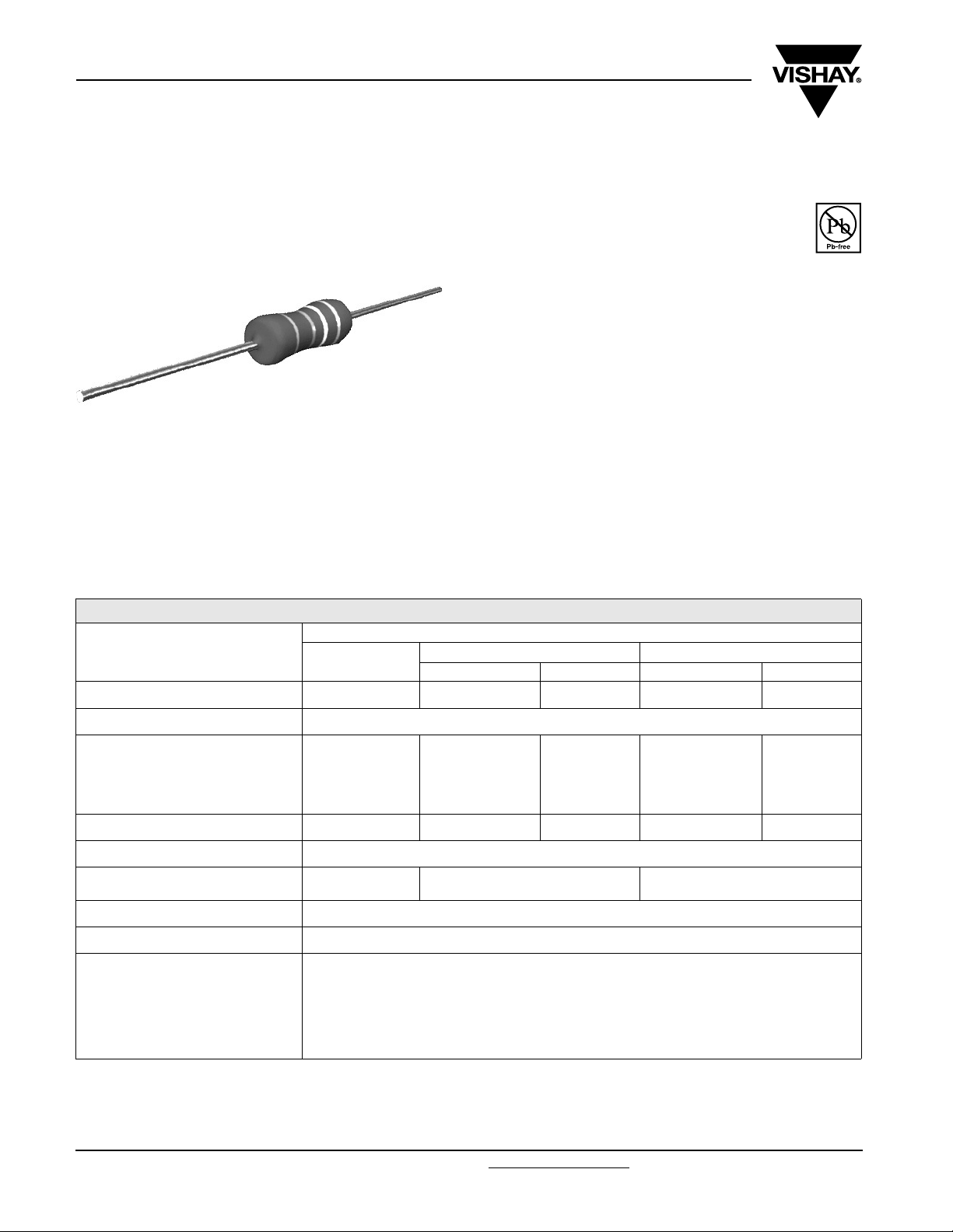
PR01/02/03
Vishay BCcomponents
Power Metal Film Resistors
FEATURES
• High power in small packages (1 W/0207 size to
3 W/0617 size)
• Different lead materials for different applications
• Defined interruption behaviour
• Lead (Pb)-free solder contacts
• Pure tin plating provides compatibility with lead (Pb)-free
and lead containing soldering processes
• Compatible with “Restriction of the use of Hazardous
Substances” (RoHS) directive 2002/95/EC (issue 2004)
APPLICATIONS
• All general purpose power applications
A homogeneous film of metal alloy is deposited on a high
grade ceramic body. After a helical groove has been cut in
the resistive layer, tinned connecting wires of electrolytic
copper or copper-clad iron are welded to the end-caps. The
resistors are coated with a red, nonflammable lacquer which
provides electrical, mechanical and climatic protection. This
coating is not resistant to aggressive fluxes. The
encapsulation is resistant to all cleaning solvents in
accordance with “MIL-STD-202E, method 215”, and
“IEC 60068-2-45”.
TECHNICAL SPECIFICATIONS
VALUE
DESCRIPTION
Resistance range
Resistance tolerance and series ± 1 % (E24, E96 series); ± 5 % (E24 series)
Maximum dissipation at T
R <1Ω 0.6 W 1.2 W − 1.6 W −
1 Ω≤R 1W 2W 1.3W 3W 2.5W
Thermal resistance (R
Temperature coefficient ≤ ± 250 x 10
Maximum permissible voltage
(DC or RMS)
Basic specifications IEC 60115-1 and 60 115-4
Climatic category (IEC 60068) 55/155/56
Stability after:
load ΔR max.: ± (5 % R + 0.1 Ω)
climatic tests ΔR max.: ± (3 % R + 0.1 Ω)
soldering ΔR max.: ± (1 % R + 0.05 Ω)
Notes:
(1)
1 % tolerance is available for Rn-range from 1 R upwards.
(2)
Ohmic values (other than resistance range) are available on request.
• R value is measured with probe distance of 24 ± 1 mm using 4- terminal method.
(2)
=70°C:
amb
) 135 K/W 75 K/W 115 K/W 60 K/W 75 K/W
th
PR01
0.22 Ω to1MΩ 0.33 Ω to1MΩ 1 Ω to1MΩ 0.68 Ω to1MΩ 1 Ω to 1 MΩ
350 V 500 V 750 V
Cu-lead FeCu-lead Cu-lead FeCu-lead
PR02 PR03
(1)
-6
/K
Document Number: 28729
Page 2
PR01/02/03
Power Metal Film Resistors
Vishay BCcomponents
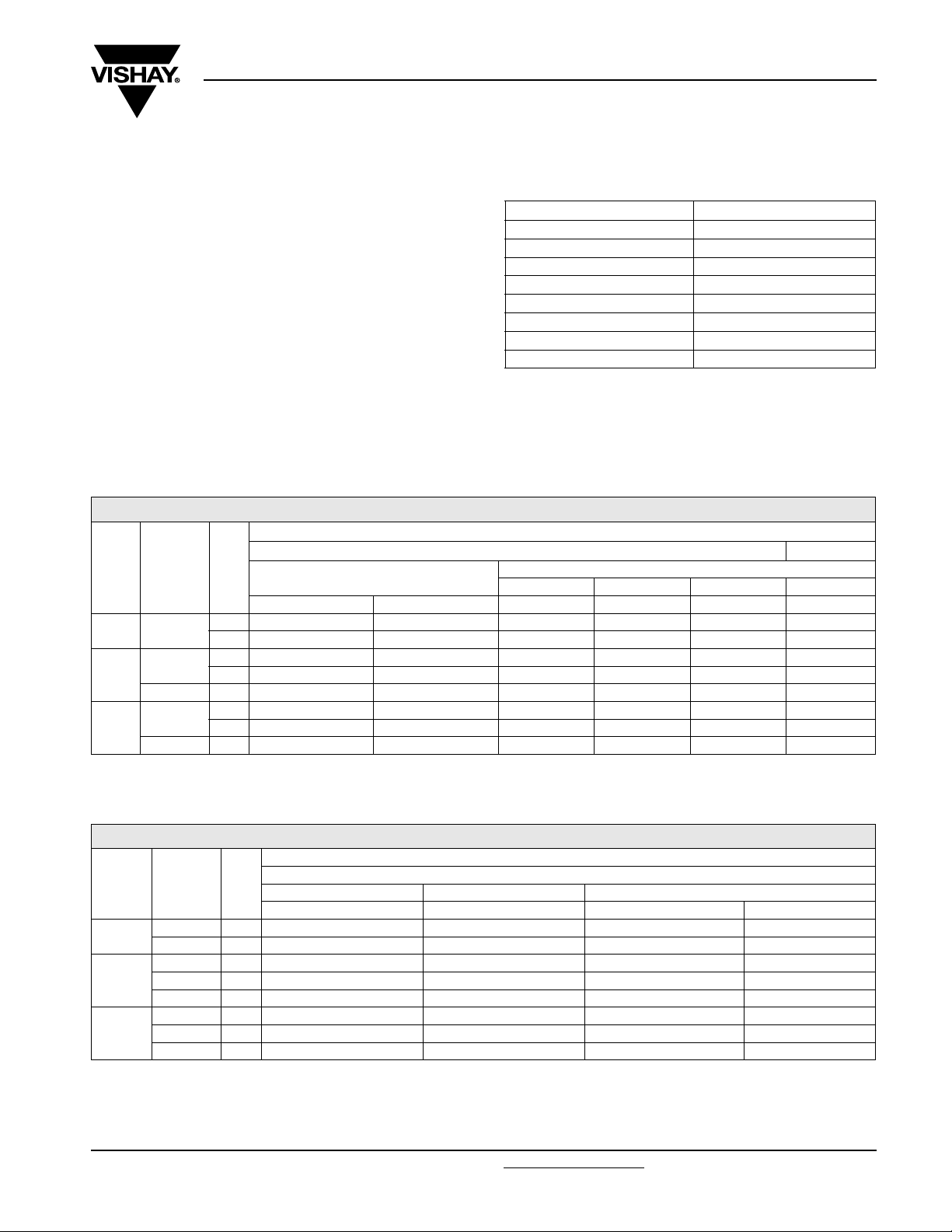
12NC INFORMATION
The resistors have a 12-digit numeric code starting with 23
For 5 % tolerance:
• The next 7 digits indicate the resistor type and packing
• The remaining 3 digits indicate the resistance value:
– The first 2 digits indicate the resistance value
– The last digit indicates the resistance decade
For 1 % tolerance:
• The next 6 digits indicate the resistor type and packing
• The remaining 4 digits indicate the resistance value:
– The first 3 digits indicate the resistance value
– The last digit indicates the resistance decade
12NC - resistor type and packaging
TYPE
PR01 Cu 0.6 1 −−22 196 1.... 06 191 2.... − 06 191 5....
PR02 Cu 0.8 1 − 22 197 2.... − 22 197 1.... − 06 192 5....
PR03 Cu 0.8 5 −−−−22 195 14... −
Notes:
(1)
Other packaging versions are available on request.
LEAD ØmmTOL
FeCu 0.6 5 −−−22 194 54... −−
FeCu 0.6 5 −−−−22 195 54... −
(%)
4000 units 3000 units 5000 units 1000 units 500 units 5000 units
5 06 197 03... − 22 193 14... 06 197 53... − 06 197 23...
5 − 06 198 03... − 06 198 53... − 06 198 23...
1 −−−−06 199 6... −
(1)
. Preferred types in bold
ORDERING CODE 23.. ... ..... (BANDOLIER)
RADIAL TAPED
Last Digit of 12NC Indicating Resistance Decade
RESISTANCE DECADE LAST DIGIT
0.22 to 0.91 Ω 7
1to9.76Ω 8
10 to 97.6 Ω 9
100 to 976 Ω 1
1to9.76kΩ 2
10 to 97.6 kΩ 3
100 to 976 kΩ 4
1MΩ 5
12NC Example
The 12NC for resistor type PR02 with Cu leads and a value
of 750 Ω with 5 % tolerance, supplied on a bandolier of
1000 units in ammopack, is: 2306 198 53751.
AMMOPACK REEL
STRAIGHT LEADS
52 mm 52 mm 63 mm 52 mm
12NC - resistor type and packaging. Preferred types in bold
ORDERING CODE 23.. ... ..... (LOOSE IN BOX)
TYPE
PR01 Cu 0.6 5 22 193 03... −−−
PR02 Cu 0.8 5 22 194 23... −−−
PR03 Cu 0.8 5 − 22 195 23... −−
Notes:
(2)
PR01 pitch 12.5 mm.
(3)
PR02 pitch 15.0 mm.
(4)
PR03 pitch 20.0 mm, with reversed kinking direction as opposed to the drawing for the type with double kink figure.
LEAD ØmmTOL
(%)
FeCu 0.6 5 22 193 43... − 22 193 53...
FeCu 0.6 5 22 194 83... −−−
FeCu 0.8 5 −−22 194 63...
FeCu 0.6 5 − 22 195 83... −−
FeCu 0.8 5 −−−22 195 63...
PITCH = 17.8 mm PITCH = 25.4 mm
1000 units 500 units 1000 units 500 units
DOUBLE KINK
PITCH
(2)
(3)
(2) (3) (4)
−
−
(4)
www.vishay.com
Page 3
PR01/02/03
Vishay BCcomponents
Power Metal Film Resistors
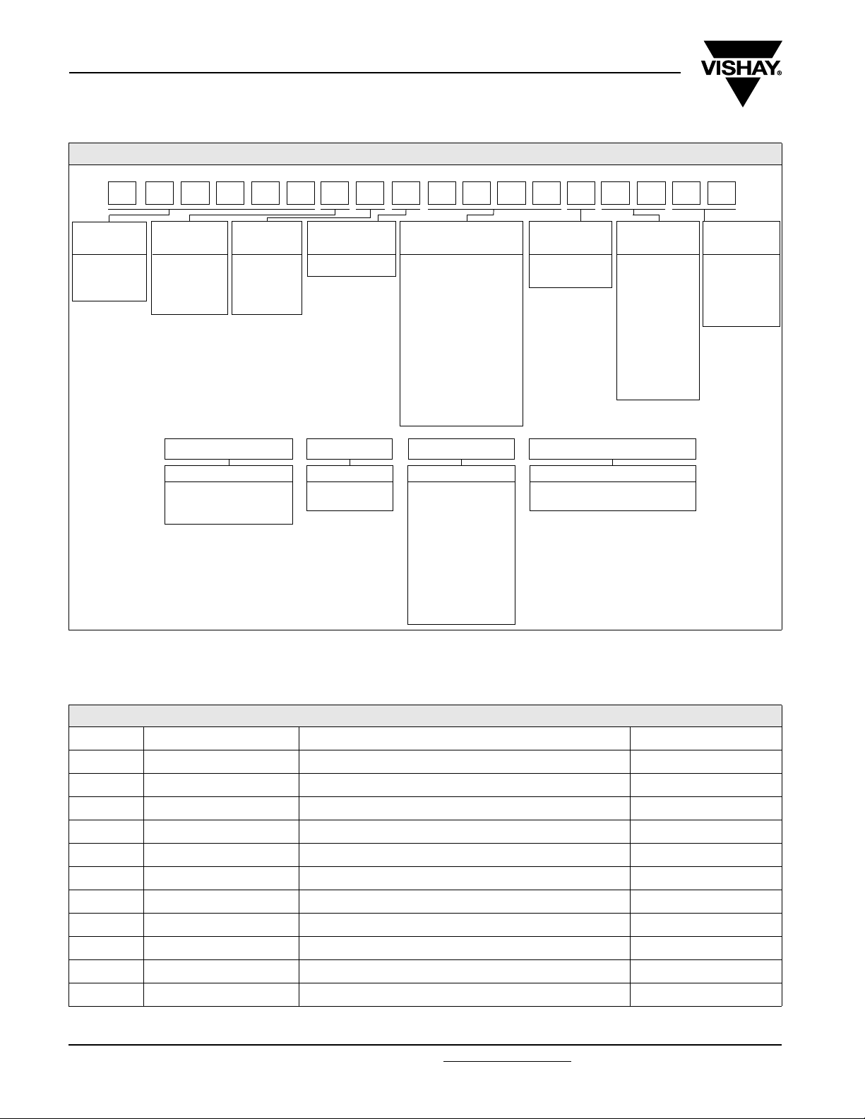
PART NUMBER
PART NUMBER: PR02000201001JA100
200RP 00201001JA100
MODEL/SIZE
PR0100
PR0200
PR0300
SPECIAL
CHARACTER
0 = neutral
Z = value
overflow
(Special)
PRODUCT DESCRIPTION: PR02 5 % A1 1K0
MODEL/SIZE TOLERANCE PACKAGING
Note:
(1)
Please refer to table PACKAGING for details.
• The PART NUMBER is shown to facilitate the introduction of a unified part numbering system for ordering products.
WIRE
TYPES
1 = Cu 0.6
2 = Cu 0.8
3 = FeCu 0.6
4 = FeCu 0.8
TCR/MATERIAL VALUE TOLERANCE
0 = standard 3 digit value
1 digit multiplier
Multiplier:
-3
7 = *10
-2
8 = *10
-1
9 = *10
0
0 = *10
1
1 = *10
2
2 = *10
3
3 = *10
4
4 = *10
5
5 = *10
F = ± 1 %
J = ± 5 %
PR02 5 % A1 1K0
PR01
PR02
PR03
± 1 %
± 5 %
(1)
N4
N3
A5
RESISTANCE VALUE
1K0 = 1 kΩ
4K75 = 4.75 kΩ
A1
AC
R5
L1
DC
K1
B1
PC
PACKAGING
N4
N3
A5
A1
AC
R5
L1
DC
K1
B1
PC
(1)
SPECIAL
The 2 digits
are used for
all special
00 = standard
parts.
PACKAGING
CODE PIECES DESCRIPTION MODEL/SIZE
N4 4000 Bandolier in ammopack radial taped PR01
N3 3000 Bandolier in ammopack radial taped PR02
A5 5000 Bandolier in ammopack straight leads 52 mm PR01
A1 1000 Bandolier in ammopack straight leads 52 mm PR01, PR02
AC 500 Bandolier in ammopack straight leads 63 mm PR03
R5 5000 Bandolier on reel straight leads 52 mm PR01, PR02
L1 1000 Loose in box with Double Kink, pitch 17.8 mm PR01, PR02
DC 500 Loose in box with Double Kink, pitch 25.4 mm PR03
K1 1000 Loose in box with Double Kink, pitch 12.5 mm PR01
B1 1000 Loose in box with Double Kink, pitch 15.0 mm PR02
PC 500 Loose in box with Double Kink, pitch 20.0 mm PR03
www.vishay.com For technical questions, contact: [email protected] Document Number: 28729
108 Revision: 06-Dec-07
Page 4
PR01/02/03
Power Metal Film Resistors
Vishay BCcomponents
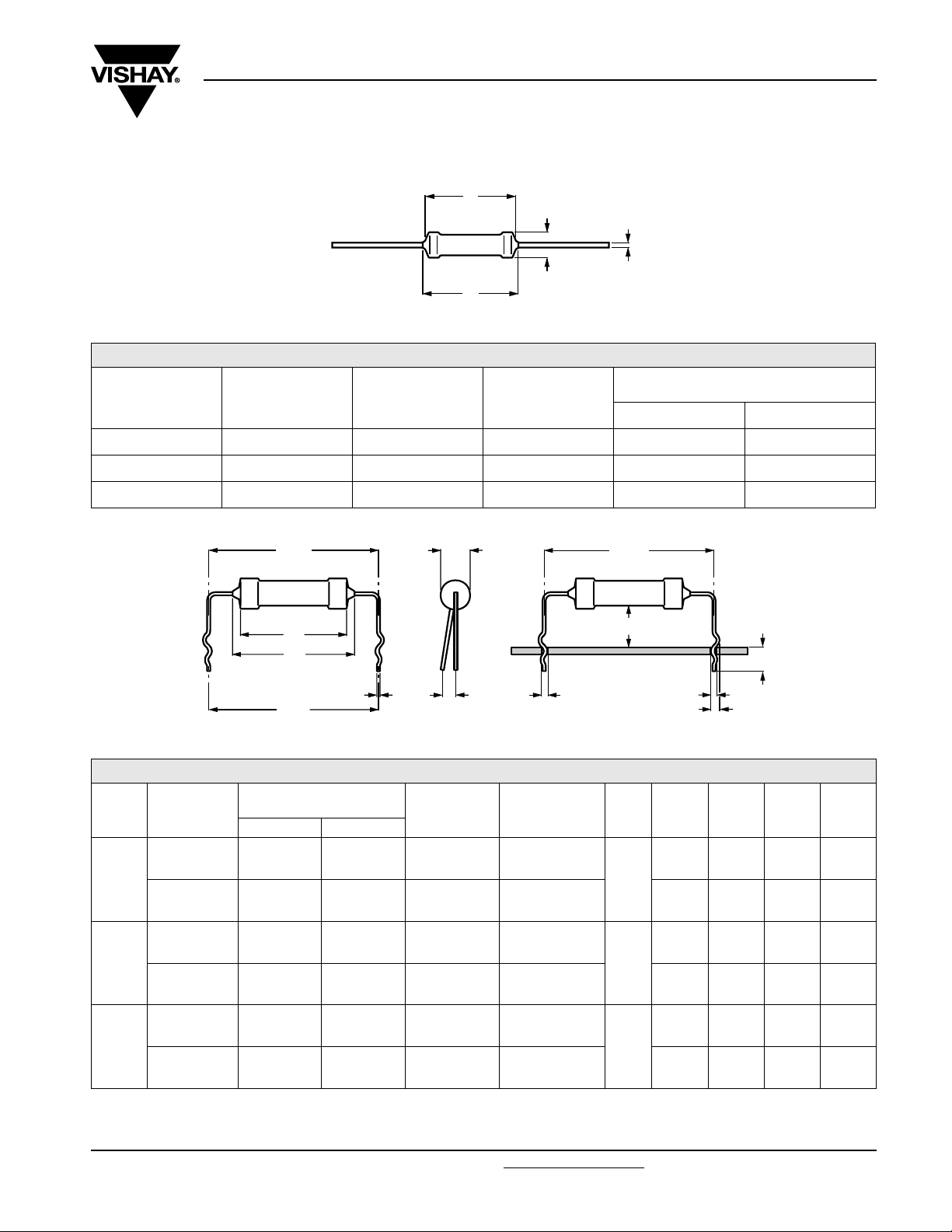
DIMENSIONS
L
1
Ø d
L
2
Ø D
Type with straight leads
DIMENSIONS - straight lead type and relevant physical dimensions; see straight leads outline
Ø d
(mm)
TYPE
Ø D
MAX.
(mm)
L
1
MAX.
(mm)
L
2
MAX.
(mm)
Cu FeCu
PR01 2.5 6.5 8.5 0.58 ± 0.05 -
PR02 3.9 10.0 12.0 0.78 ± 0.05 0.58 ± 0.05
PR03 5.2 16.7 19.5 0.78 ± 0.05 0.58 ± 0.05
P
± 0.5
1
L
1
L
2
P
± 3
2
Ø d
Ø D
S
Ø B
± 0.07
Type with double kink
P 1 ± 0.5
8 + 2
b
Dimensions in millimeters
+ 1
4.5
1
b
2
DIMENSIONS - double kink lead type and relevant physical dimensions; see double kinked outline
TYPE LEAD STYLE
double kink
large pitch
PR01
double kink
small pitch
double kink
large pitch
PR02
double kink
small pitch
double kink
large pitch
PR03
double kink
small pitch
Ø d
(mm)
Cu FeCu
0.58 ± 0.05 0.58 ± 0.05
- 0.58 ± 0.05
0.78 ± 0.05 0.58 ± 0.05
- 0.78 ± 0.05
0.78 ± 0.05 0.58 ± 0.05
- 0.78 ± 0.05
b
1
(mm)
1.10
+ 0.25/- 0.20
1.10
+ 0.25/- 0.20
1.10
+ 0.25/- 0.20
1.30
+ 0.25/- 0.20
1.10
+ 0.25/- 0.20
1.30
+ 0.25/- 0.20
b
2
(mm)
1.45
+ 0.25/- 0.20
1.45
+ 0.25/- 0.20
1.45
+ 0.25/- 0.20
1.65
+ 0.25/- 0.20
1.65
+ 0.25/- 0.20
2.15
+ 0.25/- 0.20
Ø D
MAX.
(mm)
2.5
3.9
5.2
P
1
(mm)
P
2
(mm)
17.8 17.8 2 0.8
12.5 12.5 2 0.8
17.8 17.8 2 0.8
15.0 15.0 2 1.0
25.4 25.4 2 1.0
22.0 20.0 2 1.0
0
S
MAX.
(mm)
Ø B
(mm)
Document Number: 28729 For technical questions, contact: [email protected]
www.vishay.com
Revision: 06-Dec-07 109
Page 5
PR01/02/03
≤
Vishay BCcomponents
MASS PER 100 UNITS
TYPE
PR01 Cu 0.6 mm 21.2
PR01 FeCu 0.6 mm 20.7
PR02 Cu 0.8 mm 50.4
PR02 FeCu 0.6 mm 40.6
PR02 FeCu 0.8 mm 49.6
PR03 Cu 0.8 mm 119.2
PR03 FeCu 0.6 mm 107.9
PR03 FeCu 0.8 mm 118.5
MARKING
The nominal resistance and tolerance are marked on the
resistor using four colored bands in accordance with IEC
publication 60062, “Color codes for fixed resistors”.
OUTLINES
The length of the body (L1) is measured by inserting the
leads into holes of two identical gauge plates and moving
these plates parallel to each other until the resistor body is
clamped without deformation (“IEC publication 60 294”).
Power Metal Film Resistors
MOUNTING
MASS
(g)
The resistors are suitable for processing on automatic
insertion equipment and cutting and bending machines.
MOUNTING PITCH
TYPE LEAD STYLE
PR01
PR02
PR03
Note:
(1)
Recommended minimum value.
PITCH
mm e
straight leads 12.5
(1)
5
radial taped 4.8 2
double kink large pitch 17.8 7
double kink small pitch 12.5 5
straight leads 15.0
(1)
6
radial taped 4.8 2
double kink large pitch 17.8 7
double kink small pitch 15.0 6
straight leads 23.0
(1)
9
double kink large pitch 25.4 10
double kink small pitch 20.0 8
FUNCTIONAL DESCRIPTION
PRODUCT CHARACTERIZATION
Standard values of nominal resistance are taken from the E96/E24 series for resistors with a tolerance of ± 1 % or ± 5 %.
The values of the E96/E24 series are in accordance with “IEC publication 60063”.
FUNCTIONAL PERFORMANCE
< 1 kΩ
51 kΩ
T
amb
(1)
= 40 °C
(°C)
T
m
LIMITING
POWER
(W)
0.6
1.2
1.6
= 40 °C
T
1.00
P
(W)
0.75
0.50
0.25
100 000 h
10 000 h
1000 h
∆
R
2.05.0
10
1.0
0.1 %0.20.5
amb
< 30 k
> 30 k
< 1 k
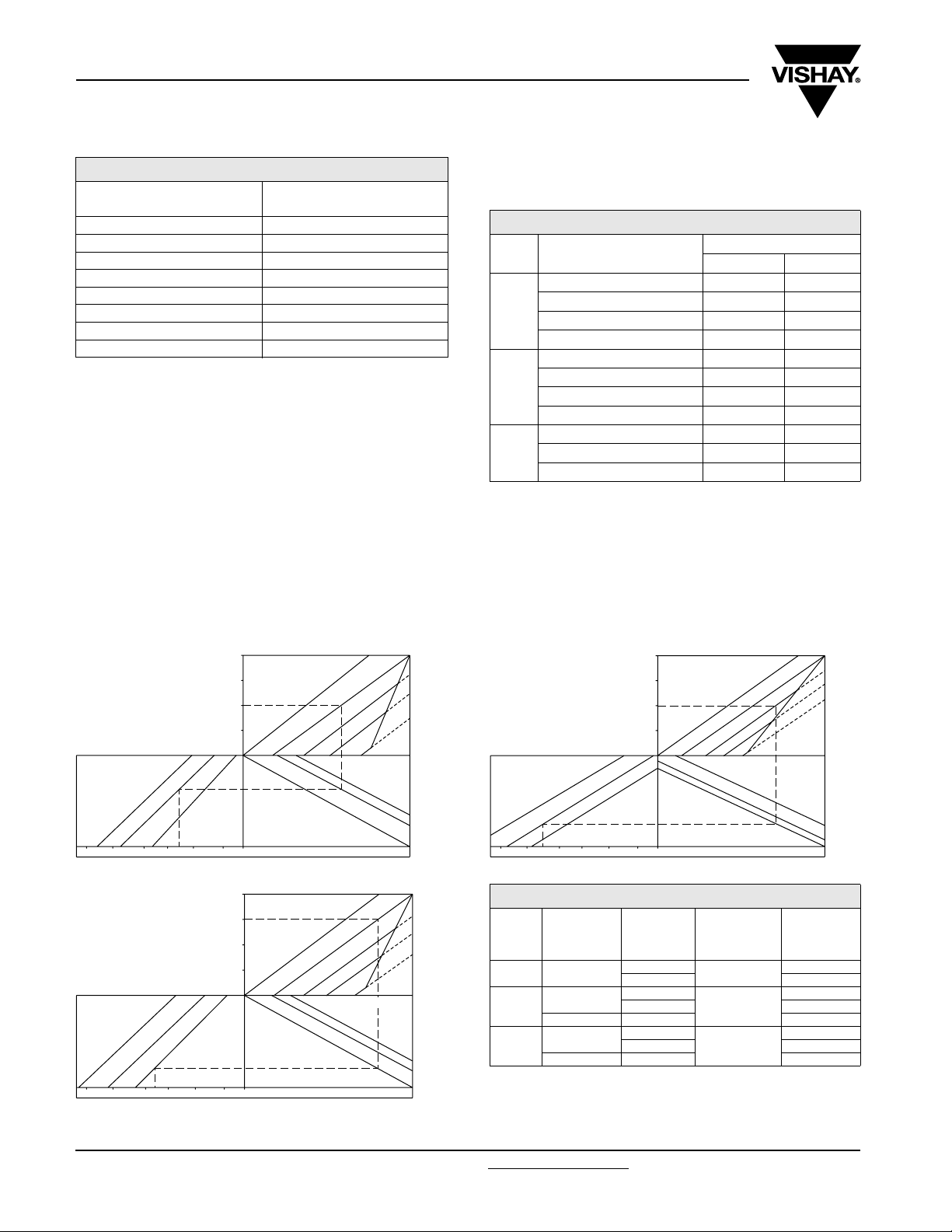
PR01 Drift nomogram
= 40 °C
T
2.00
P
(W)
1.50
1.00
0.50
100 000 h
10 000 h
1000 h
∆
5.0
10
2.0 1.0 0.5 0.2 0.1 %
R
amb
< 1 kΩ
< 39 kΩ
> 39 kΩ
PR02 Drift nomogram
70 °C
100 °C
125 °C
155 °C
205 °C
(°C)
T
m
Ω
Ω
Ω
10 5.0 2.0
100 000 h
10 000 h
1000 h
1.0 0.5
(W)
3.00
P
2.25
1.50
0.75
> 51 kΩ
∆
R
0.1 %
0.2
PR03 Drift nomogram
T
(°C)
m
70 °C
100 °C
125 °C
155 °C
220 °C
LIMITING VALUES
TYPE
PR01
PR02
LEAD
MATERIAL
Cu
Cu
FeCu
PR03
Cu
FeCu
Note:
(1)
The maximum voltage that may be continuously applied to the
RANGE
R <1Ω
1 Ω≤R 1.0
R <1Ω
1 Ω≤R 2.0
1 Ω≤R 1.3
R <1Ω
1 Ω≤R 3.0
1 Ω≤R 2.5
LIMITING
VOLTAGE
(V)
350
500
750
resistor element, see “IEC publication 60115-1”.
The maximum permissible hot-spot temperature is 205 °C for PR01,
220 °C for PR02 and 250 °C for PR03.
(1)
(1)
(1)
70 °C
100 °C
125 °C
155 °C
250 °C
www.vishay.com For technical questions, contact: [email protected] Document Number: 28729
110 Revision: 06-Dec-07
Page 6

PR01/02/03
Power Metal Film Resistors
The power that the resistor can dissipate depends on the operating temperature.
P
max
(%
)
P
rate d
100
50
Derating
Maximum dissipation (P
3
10
P
ma x
(W )
2
10
10
1
0
) in percentage of rated power as a function of the ambient temperature (T
max
= 1000
tpt
/
i
500
200
100
50
20
10
5
2
0
70 100 50
Vishay BCcomponents
amb
( °C)
155 - 55
)
amb
T
-1
10
-6
10
-5
10
-4
10
-3
10
PR01 Pulse on a regular basis; maximum permissible peak pulse power as a function of pulse duration (ti)
1200
V
ma x
(V)
1000
800
600
400
200
0
-6
10
-5
10
-4
10
-3
10
PR01 Pulse on a regular basis; maximum permissible peak pulse voltage as a function of pulse duration (ti)
-2
10
P
()
max
-2
10
V
()
max
-1
10
-1
10
1
t
(s)
i
1
(s)
t
i
Pulse Loading Capabilities
www.vishay.com
Page 7

PR01/02/03
Vishay BCcomponents
3
10
P
max
(W)
2
10
10
1
-1
10
-6
10
PR02 Pulse on a regular basis; maximum permissible peak pulse power as a function of pulse duration (ti)
1700
V
max
(V)
1500
t
t
/ i = 1000
p
10
Power Metal Film Resistors
500
200
100
50
20
10
5
2
-5
-4
10
-3
10
-2
10
P
()
max
-1
10
1
t
(s)
i
1300
1100
900
700
500
-6
10
PR02 Pulse on a regular basis; maximum permissible peak pulse voltage as a function of pulse duration (ti)
4
10
P
max
(W)
3
10
2
10
10
-5
10
t
t
/ i = 1000
p
100
10
-4
10
500
200
50
20
5
2
-3
10
-2
10
V
()
max
-1
10
t
1
(s)
i
1
-6
10
PR03 Pulse on a regular basis; maximum permissible peak pulse power as a function of pulse duration (ti)
-5
10
-4
10
-3
10
-2
10
P
()
max
-1
10
1
t
(s)
i
Pulse Loading Capabilities
www.vishay.com For technical questions, contact: [email protected] Document Number: 28729
112 Revision: 06-Dec-07
Page 8

PR01/02/03
2400
V
max
(V)
2000
1600
1200
800
400
0
-6
10
PR03 Pulse on a regular basis; maximum permissible peak pulse voltage as a function of pulse duration (ti)
Pulse Loading Capabilities
2
10
t
(s)
Power Metal Film Resistors
-5
10
-4
10
-3
10
-2
10
V
()
max
2
10
t
(s)
Vishay BCcomponents
-1
10
1
t
(s)
i
10
1
-1
10
0
10
P
overload
50
40 20 30
(W )
PR01 Time to interruption as a function of overload power
for range: 0 R 22 ≤ R
< 1 R
n
This graph is based on measured data under constant voltage
conditions; the data may deviate according to the applications.
2
10
t
(s)
10
1
10
1
-1
10
0
10
P
overload
50
40 20 30
(W )
PR01 Time to interruption as a function of overload power
for range: 16 R ≤ R
≤ 560 R
n
This graph is based on measured data under constant voltage
conditions; the data may deviate according to the applications.
2
10
t
(s)
10
1
-1
10
0
10
P
overload
50
40 20 30
(W )
PR01 Time to interruption as a function of overload power
for range: 1 R ≤ R
≤ 15 R
n
This graph is based on measured data under constant voltage
conditions; the data may deviate according to the applications.
This graph is based on measured data under constant voltage
conditions; the data may deviate according to the applications.
-1
10
0
20
80 40 60
P
overload
100
(W )
120
PR02 Time to interruption as a function of overload power
for range: 0.33 R ≤ R
n
< 5 R
Interruption Characteristic
www.vishay.com
Page 9

PR01/02/03
Vishay BCcomponents
2
10
t
(s)
10
1
-1
10
20
0
80 40 60
Power Metal Film Resistors
100
P
overload
(W )
120
PR02 Time to interruption as a function of overload power
for range: 5 R ≤ R
< 68 R
n
This graph is based on measured data under constant voltage
conditions; the data may deviate according to the applications.
2
10
t
(s)
2
10
t
(s)
10
1
-1
10
20
0
80 40 60
P
overload
100
(W )
120
PR02 Time to interruption as a function of overload power
for range: 68 R ≤ R
≤ 560 R
n
This graph is based on measured data under constant voltage
conditions; the data may deviate according to the applications.
Interruption Characteristics
200
∆
T
(K)
160
10
1
-1
10
0 200 100 150
50
P
overload
(W )
250
PR03 Time to interruption as a function of overload power
for range: 0.68 R ≤ R
≤ 560 R
n
This graph is based on measured data under constant voltage
conditions; the data may deviate according to the applications.
100
∆
T
(K)
80
60
40
20
15 mm
20 mm
25 mm
120
80
40
0
0 0.4 1.2
Ø 0.6 mm Cu-leads
PR01 Hot-spot temperature rise (ΔT) as a function
200
∆
T
(K)
160
120
80
40
of dissipated power.
0.8
P
(W )
0
Ø 0.6 mm Cu-leads
0 0.4 1.2
0.8
P
(W )
Minimum distance from resistor body to PCB = 1 mm
PR01
Temperature rise (ΔT
) at the lead end (soldering point)
Ø 0.6 mm FeCu-leads
as a
0
0 0.4 1.2
0.8
P
(W )
PR01 Hot-spot temperature rise (ΔT) as a function
of dissipated power.
function of dissipated power at various lead lengths after mounting.
Application Information
www.vishay.com For technical questions, contact: [email protected] Document Number: 28729
114 Revision: 06-Dec-07
Page 10

PR01/02/03
Power Metal Film Resistors
100
∆
T
(K)
80
60
P
(W )
15 mm
20 mm
25 mm
15 mm
20 mm
25 mm
40
20
0
0 0.4 1.2
0.8
Ø 0.6 mm FeCu-leads
Minimum distance from resistor body to PCB = 1 mm
PR01
Temperature rise (ΔT
) at the lead end (soldering point)
function of dissipated power at various lead lengths after mounting.
100
T
∆
(K)
80
60
40
as a
200
∆
T
(K)
160
120
80
40
0
0 0.8 2.4
Ø 0.8 mm Cu-leads
PR02 Hot-spot temperature rise (ΔT) as a function
240
∆
T
(K)
200
160
120
80
Vishay BCcomponents
1.6
P
(W )
of dissipated power.
20
0
0 2
Ø 0.8 mm Cu-leads
1
P
(W )
Minimum distance from resistor body to PCB = 1 mm
PR02
Temperature rise (ΔT
) at the lead end (soldering point)
function of dissipated power at various lead lengths after mounting.
100
T
∆
(K)
80
60
40
20
0
Ø 0.6 mm FeCu-leads
1
15 mm
20 mm
25 mm
P
(W )
20
Minimum distance from resistor body to PCB = 1 mm
PR02
Temperature rise (ΔT
) at the lead end (soldering point)
function of dissipated power at various lead lengths after mounting.
as a
as a
40
0
0 0.8 2.4
Ø 0.6 mm FeCu-leads
PR02 Hot-spot temperature rise (ΔT) as a function
240
∆
T
(K)
200
160
120
80
40
0
01
Ø 0.8 mm FeCu-leads
PR02 Hot-spot temperature rise (ΔT) as a function
1.6
of dissipated power.
of dissipated power.
P
(W )
P
(W )
2
Application Information
www.vishay.com
Page 11

PR01/02/03
Vishay BCcomponents
100
∆
T
(K)
80
60
40
20
0
Ø 0.8 mm FeCu-leads
0 1.6 2.4
0.8
Power Metal Film Resistors
15 mm
20 mm
25 mm
P
(W )
Minimum distance from resistor body to PCB = 1 mm
PR02
Temperature rise (ΔT
) at the lead end (soldering point)
function of dissipated power at various lead lengths after mounting.
100
∆
T
(K)
80
15 mm
as a
200
∆
T
(K)
160
120
80
40
0
01 3
Ø 0.8 mm Cu-leads
PR03 Hot-spot temperature rise (ΔT) as a function
240
∆
T
(K)
200
of dissipated power.
2
P
(W )
60
40
20
0
01 3
Ø 0.8 mm Cu-leads
20 mm
25 mm
2
P
(W )
Minimum distance from resistor body to PCB = 1 mm
PR03
Temperature rise (ΔT
) at the lead end (soldering point)
function of dissipated power at various lead lengths after mounting.
100
∆
T
(K)
80
60
40
20
10 mm
15 mm
20 mm
25 mm
as a
160
120
80
40
0
01 3
Ø 0.6 mm FeCu-leads
PR03 Hot-spot temperature rise (ΔT) as a function
240
∆
T
(K)
200
160
120
80
40
of dissipated power.
2
P
(W )
0
Ø 0.6 mm FeCu-leads
01 3
Minimum distance from resistor body to PCB = 1 mm
PR03
Temperature rise (ΔT
) at the lead end (soldering point)
2
P
(W )
Ø 0.8 mm FeCu-leads
01 0 32
P
(W )
PR03 Hot-spot temperature rise (ΔT) as a function
as a
of dissipated power.
function of dissipated power at various lead lengths after mounting.
Application Information
www.vishay.com For technical questions, contact: [email protected] Document Number: 28729
116 Revision: 06-Dec-07
Page 12

PR01/02/03
Power Metal Film Resistors
Vishay BCcomponents
100
∆
T
(K)
80
15 mm
60
20 mm
40
20
0
Ø 0.8 mm FeCu-leads
0 1.6 3.2 2.4
0.8
P
(W )
Minimum distance from resistor body to PCB = 1 mm
PR03
Temperature rise (ΔT
) at the lead end (soldering point)
as a function
of dissipated power at various lead lengths after mounting.
2
10
Z
R
10
R
= 1 Ω
n
1
-1
10
-2
10
12 0
ϕ(deg )
80
40
- 40
- 80
10
n = 24 Ω
R
= 12 kΩ
R
n
= 100 kΩ
R
n
-1
10 1
10
2
f (MHz)
10
3
PR01 Impedance as a function of applied frequency
= 1 Ω
R
n
n = 24 Ω
R
0
= 12 kΩ
R
n
= 100 kΩ
R
n
-1
10 1 10
2
10
f (MHz )
3
10
PR01 Phase angle as a function of applied frequency
Application Information
www.vishay.com
Page 13

PR01/02/03
Vishay BCcomponents
2
10
Z
R
10
1
-1
10
-2
10
-1
10
120
ϕ(deg)
80
40
Power Metal Film Resistors
2
10 1
PR02 Impedance as a function of applied frequency
10
= 1.2 Ω
R
n
n = 10 Ω
R
= 22 kΩ
R
n
= 124 kΩ
R
n
= 1.2 Ω
R
n
= 10 Ω
R
n
f (MHz)
3
10
- 40
- 80
- 120
10
Z
R
10
1
-1
10
-2
10
0
R
= 22 k Ω
n
= 124 k Ω
R
n
-1
10 1 10
10
2
f (MHz)
10
3
PR02 Phase angle as a function of applied frequency
2
= 1.5 Ω
R
n
= 18 Ω
R
n
= 1.3 k Ω
R
n
= 20 k Ω
R
n
= 100 k Ω
R
n
2
10 1
10
f (MHz )
10
3
PR03 Impedance as a function of applied frequency
Application Information
www.vishay.com For technical questions, contact: [email protected] Document Number: 28729
118 Revision: 06-Dec-07
Page 14

PR01/02/03
Power Metal Film Resistors
90
ϕ(deg)
60
30
0
- 30
- 60
- 90
PR03 Phase angle as a function of applied frequency
Application Information
TESTS AND REQUIREMENTS
Essentially all tests are carried out in accordance with the
schedule of “IEC publication 60115-1”, category
LCT/UCT/56 (rated temperature range: Lower Category
Temperature, Upper Category Temperature; damp heat,
long term, 56 days). The testing also covers the
requirements specified by EIA and EIAJ.
The tests are carried out in accordance with IEC publication
60068-2, “Recommended basic climatic and mechanical
robustness testing procedure for electronic components” and
under standard atmospheric conditions according to
10 1
Vishay BCcomponents
= 1.5 Ω
R
n
= 18 Ω
R
n
= 1.3 k Ω
R
n
= 20 k Ω
R
n
R
= 100 k Ω
n
f (MHz )
10
2
“IEC 60068-1”, subclause 5.3.
In the Test Procedures and Requirements table, tests
and requirements are listed with reference to the relevant
clauses of “IEC publications 60115-1 and 60 068-2”; a short
description of the test procedure is also given. In some
instances deviations from the IEC recommendations were
necessary for our method of specifying.
All soldering tests are performed with mildly activated flux.
10
3
TEST PROCEDURES AND REQUIREMENTS
IEC
60115-1
CLAUSE
TESTS IN ACCORDANCE WITH THE SCHEDULE OF IEC PUBLICATION 60115-1
4.4.1 visual examination no holes; clean surface; no damage
4.4.2 dimensions (outline) gauge (mm)
4.5
4.18 20 (Tb)
4.29 45 (Xa)
4.17 20 (Ta) solderability 2 seconds; 235 °C good tinning; no damage
IEC
60068-2
TEST
METHOD
TEST PROCEDURE REQUIREMENTS
resistance
(refer note on first page
for measuring distance)
resistance to soldering heat
component solvent
resistance
see Straight & Kinked Dimensions tables
applied voltage (+ 0/- 10 %):
R <10Ω: 0.1 V
10 Ω≤R < 100 Ω:0.3V
100 Ω≤R <1kΩ:1V
1kΩ≤R <10kΩ:3V
R - R
:max. ± 5 %
nom
10 kΩ≤R < 100 kΩ:10V
100 kΩ≤R <1MΩ:25V
R = 1 MΩ:50V
thermal shock: 3 s; 350 °C; 3 mm from body ΔR max.: ± (1 % R + 0.05 Ω)
isopropyl alcohol or H
followed by brushing
O
2
no visual damage
in accordance with “MIL 202 F”
www.vishay.com
Page 15

PR01/02/03
Vishay BCcomponents
Power Metal Film Resistors
TEST PROCEDURES AND REQUIREMENTS
IEC
60115-1
CLAUSE
4.7
4.16 21 (U)
4.16.2 21 (Ua1) tensile all samples load 10 N; 10 seconds number of failures: < 1 x 10
4.16.3 21 (Ub)
4.16.4 21 (Uc)
4.20 29 (Eb) bump 3 x 1500 bumps in three directions; 40 g
4.22 6 (Fc) vibration
4.19 14 (Na)
4.23 climatic sequence:
4.23.3 30 (Db)
4.23.6 30 (Db)
4.24.2 3 (Ca)
4.25.1 endurance (at 70 °C)
4.8.4.2
OTHER TESTS IN ACCORDANCE WITH IEC 60115 CLAUSES AND IEC 60 068 TEST METHOD
4.17 20 (Tb)
4.6.1.1 insulation resistance
nd
see 2
IEC 60115-1, Jan. ’87
IEC
60068-2
TEST
METHOD
amendment to
TEST PROCEDURE REQUIREMENTS
voltage proof on
insulation
maximum voltage 500 V
during 1 minute; metal block method
RMS
no breakdown or flashover
robustness of terminations:
bending half number of samples
torsion other half of samples
load 5 N; 4 x 90° number of failures: < 1 x 10
3 x 360° in opposite directions
no damage ΔR
no damage ΔR
max.:± (
max.:± (
frequency 10 to 500 Hz;
displacement 1.5 mm or
acceleration 10 g; three directions; total
ΔR max.: ± (0.5 % R + 0.05 Ω)
no damage
6 hours (3 x 2 hours)
no visual damage
rapid change of
temperature
30 minutes at LCT and
30 minutes at UCT; 5 cycles
PR01: ΔR max.: ± (1 % R + 0.05 Ω)
PR02: ΔR max.: ± (1 % R + 0.05 Ω)
PR03: ΔR max.: ± (2 % R + 0.05 Ω)
damp heat
(accelerated) 1
damp heat
(accelerated) remaining
damp heat
(steady state) (IEC)
temperature coefficient
solderability
(after ageing)
cycles
st
cycle
6 days; 55 °C; 95 to 98 % RH
56 days; 40 °C; 90 to 95% RH; loaded with
0.01 P
(IEC steps: 4 to 100 V)
n
1000 hours; loaded with P
1.5 hours ON and 0.5 hours OFF
at 20/LCT/20 °C and 20/UCT/20 °C
(TC x 10
-6
/K)
8 hours steam or 16 hours 155 °C; leads
immersed 6 mm for 2 ± 0.5 second in a solder
bath at 235 ± 5 °C
maximum voltage (DC) after 1 minute; metal
block method
or V
n
max
min.: 103MΩ
R
ins
ΔR max.: ± (3 % R + 0.1 Ω)
R
min.: 1000 MΩ
ins
ΔR max.: ± (3 % R + 0.1 Ω)
;
ΔR max.: ± (5 % R + 0.1 Ω)
≤ ± 250
good tinning (≥ 95 % covered);
no damage
R
min.: 104MΩ
ins
pulse load see Pulse Load Capabilities graphs
0.5 % R+0.05Ω)
0.5 %R + 0.05Ω)
-6
-6
www.vishay.com For technical questions, contact: [email protected] Document Number: 28729
120 Revision: 06-Dec-07
Page 16

Legal Disclaimer Notice
Vishay
Notice
Specifications of the products displayed herein are subject to change without notice. Vishay Intertechnology, Inc.,
or anyone on its behalf, assumes no responsibility or liability for any errors or inaccuracies.
Information contained herein is intended to provide a product description only. No license, express or implied, by
estoppel or otherwise, to any intellectual property rights is granted by this document. Except as provided in Vishay's
terms and conditions of sale for such products, Vishay assumes no liability whatsoever, and disclaims any express
or implied warranty, relating to sale and/or use of Vishay products including liability or warranties relating to fitness
for a particular purpose, merchantability, or infringement of any patent, copyright, or other intellectual property right.
The products shown herein are not designed for use in medical, life-saving, or life-sustaining applications.
Customers using or selling these products for use in such applications do so at their own risk and agree to fully
indemnify Vishay for any damages resulting from such improper use or sale.
Document Number: 91000 www.vishay.com
Revision: 08-Apr-05 1
 Loading...