

Power supplies– 19" compatible – AC/DC switched-mode power supply
Single, adjustable 100 W
19" compatible – AC/DC switched-mode power supply
쮿 Adjustable output voltage range
쮿 Wide range input voltage (from 90 – 264 VAC and
100 –360 V
쮿 Single output voltage
쮿 Redundancy operation with integrated decoupling diode
쮿 Active Current Share Bus (CSB)
쮿 Signalling: Output voltage OK
Delivery comprises
11303001
Qty Description
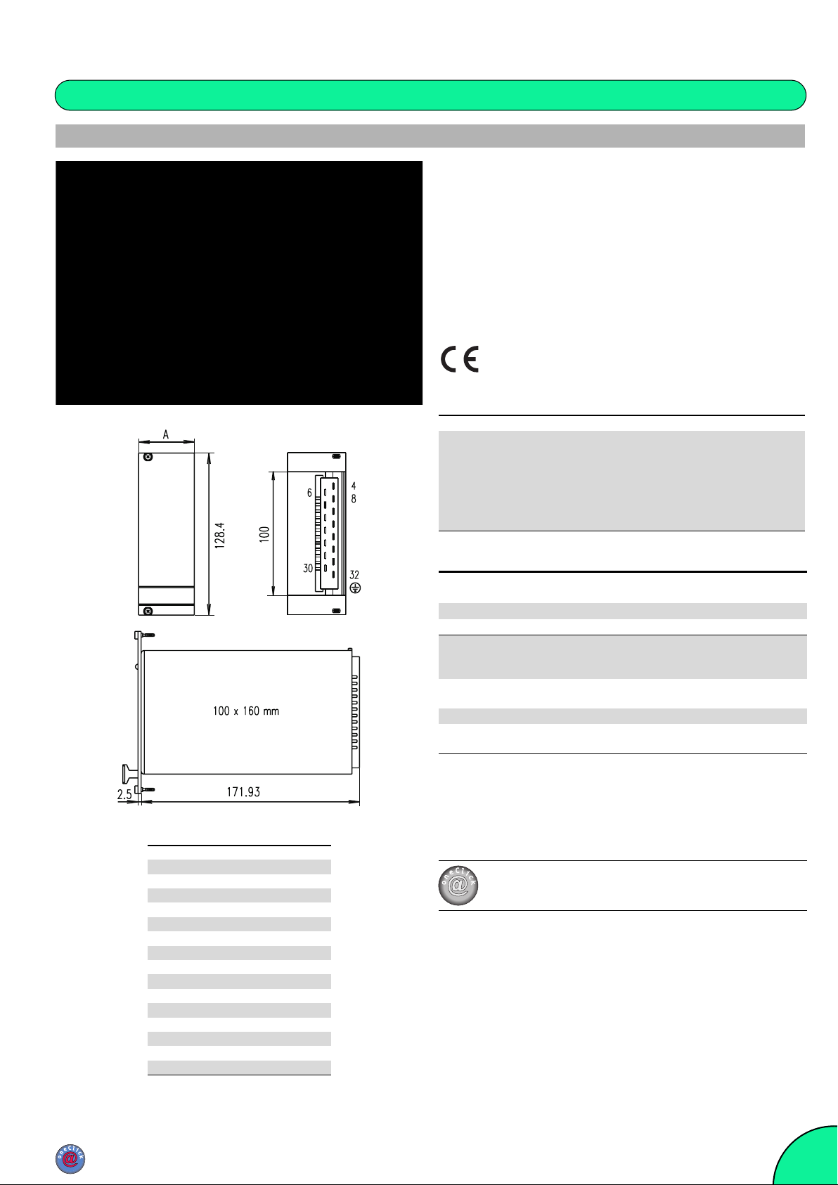
1 19" compatible power supply
height 3 U
width A: 6 HP
depth 171.93 mm (160 mm deep boards),
output voltage pre-set at 12 V or 24 V respectively
connector H 15M (assembled)
keying/coding peg (assembled)
) with active Power Factor Correction (PFC)
DC
maxpower
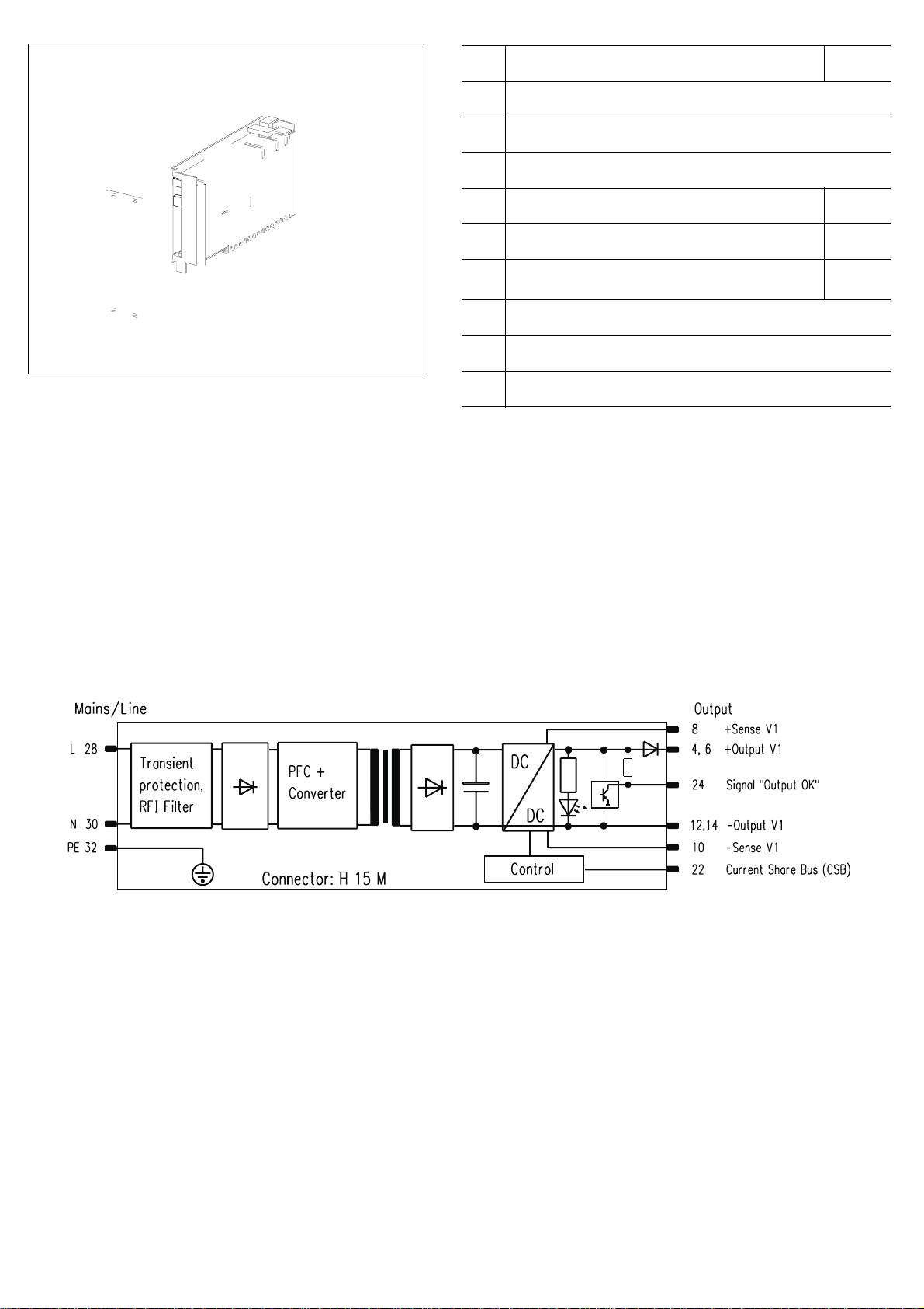
Connector pin-out
Pin Connection
4 Output + V
6 Output + V
8 Sense line + V
10 Sense line 0 V
12 Output 0 V
14 Output 0 V
16 –
18 –
20 –
22 CSB
24 Output OK
26 –
28 L
30 N
32 PE 댷
Order Information
Voltage Current Power Description Order no.
VAW
4.5–17 5.9 100 MAX LR
16–30 3.4 102 MAX UR
13100-133
13100-134
Front panel 6 HP, Al, front anodised, rear colourless
chromated, with vertical slots for EMC contact strips,
21006-954
incl. assembly kit, 1 piece
EMC contact strips Stainless steel, 2 pieces per front
panel necessary, PU 10 pieces
Connector H 15 F FASTON connection, 1 piece
Coding PU (keying/coding peg, 1 piece, keying/coding pin
2 pieces)
21101-705
69001-733
60800-123
Note
쮿 Please order front panel separately
쮿 Output data at mains/line voltage > 190 V
DIJM0084
쮿 Further accessories, see page 9.21
1
1
1
1
1
1
For further information www.schroff.biz/oneclick
oneClick code = Order no.
, Ta = 0...50 °C
AC
Electronics Packaging www.schroff.biz
UK 04/2006
9.5
Pos.
Benennung
Item
Description
Repère
Désignation
Netzgerät, T eileinsatz 3 HE nach DIN 41494, Teil 5
1
Power Supply, Plug-inunit 3 U to DIN 41494, part 5
Alimentation, Module enfichable 3 U, selonDIN 41494 partie 5
Steckverbinder Messerleiste
2
Male connector
Connecteur mâle
Codierleiste, Kammleiste
3
Coding strip, Female strip
Détrompeur, Peigne
Codierleisten-Gegenstück
4
Coding strip
Réceptacle détrompeur
Steckverbinder-Gegenstück
5
Female connector
Connecteur femelle
HF Frontplatte 6 TE (seitlichgeschlitzt) mit Befestigungsmaterial
6
EMC front panel 6 HP with slots incl. assembly parts
Face avant HF 6 F (avec fentes latérales) et pièces de fixation
Sicherung intern
7
Fuse internal
Fusiblesecteur
Power LED grün, versorgt durch die Ausgangsspannung
8
Power LED green, supplied by the ouput voltage
Power LED verte, alimentée par tension de sortie
∆ V : Einstellung der Ausgangsspannung
9
∆ V : Adjustment of the output voltages
∆ V : Réglage tensions de sortie
H 15 M, DIN 41612
Bestell-Nr.
Order No.
Référence
60800-123
69001-733
21006-954

Serienschaltung
un autreemballage approprié.
Series operation
Branchement en série
V
1
+
PSU 1
-
V
1
+
PSU 2
-
Parallelschaltung (CSB)
Parallel operation
Branchement en parallèle
Signal „Output OK“
MAX LR MAX UR
U
s 3,8 ± 0,4 V 14,1 ± 0,8 V
+
R
-
DIJM0070
DIJM0033
Leistungsbegrenzung
Zum Schutz des Gerätes muss der
Anwender bei Temperaturen > 50 °C
die Ausgangsleistung reduzieren.
Strombegrenzung
Die Geräte sind für Dauerkurzschluss
ausgelegt. Der Ausgangsstrom wird
gemäß einer U/I-Kennlinie begrenzt.
Strombegrenzung ist für 240 V
L
Betrieb eingestellt. Bei100 VFBetrieb
muss der Ausgangsstrom reduziert
werden (siehe Tabelle). Steht eine
Überlast bei 100 V
F
Zeit an, schaltet das Netzgerätab.
Wiederanlauf durch Netz aus-/
einschalten.
Wird die Ausgangsspannung vom
Anwender über die max. einstellbare
Ausgangsspannung erhöht, muss er
sicherstellen, dass der maximale Ausgangsstrom um den gleichen Faktor
verringertwird.
Beispiel: U
+10%=>IDC-10%.
DC
Überspannungsschutz (OVP)
Der OVP ist über eine zweiteRegelschleife realisiert. Schwellen siehe
Spezifikationen.
Bei einem Fehler der OVP-Schaltung
legieren die interne Schutzdioden
durch. Diese müssen werkseitig ausgetauscht werden.
Serienschaltung
Sehen Sie am Ausgang externe Inversdioden vor. BeiSerienschaltung können am Ausgang berührungsgefährliche Spannungen auftreten:
SELV-Spannung nur bis60 V
Parallelschaltung
Zur Leistungserhöhung oder Redundanzbetrieb werden die Ausgänge der
Netzgeräte parallel verbunden. Es
erfolgt eine geregelte Lastaufteilung
wenn der Current Share Bus der Netzgeräte miteinander verbunden ist (Pin
22,max.12Geräte parallelschaltbar,
max. Ausgangsleistung ca. 0.9*P
Damit im Redundanzbetrieb alle Netzgeräte arbeiten ist eine Grundlast von
erforderlich.
0,1*P
max
Die Entkoppeldiode ist eingebaut.
Netzspannung
Die Power Supplies haben einen Weitbereichseingang (90 V
Output OK Signal
Das Signal„OutputOK“ zeigt an, ob die
Ausgangsspannung vorhanden ist
(siehe Diagramm Signal „OutputOK“).
F
Betrieb längere
.
DC
max.
– 254 VAC).
AC
Output power limiting
Inorder to protecttheunit, the usermust
reduce theoutputcurrents at
temperatures > 50 °C.
Current limiting
The power supply featuresshort-circuit
protection. The output current is limited
according to a U/I diagram. Current
F
limiting is setfor240 V
100V
F
operation the output current
operation. With
must be limited (see table). If an
overload in 100 V
F
operation persists
for a long while, the power supply
switches off. Restart using the power
on/off switch.
If the output voltage is increasedby the
user to above the maximum settable
output voltage, the maximum output
current must be reduced by the same
factor.
Example: V
+10%=>IDC-10%.
DC
Over-volta ge protection (OVP)
The OVP is realized bymeans of an
additional loop. For thresholds, please
refer to the specifications.
If there is a fault in the OVP-circuit, the
internal fuse breaks. The fuse mustbe
changed
Series operation
External inverse diodesshould be used
at the output. Dangerous voltages may
occur at the output with series
operation:
SELV voltageonly up to 60 V
.
DC
Parallel operation
The unit outputs are set up for parallel
operation to increase the output power
or for redundancy. The load share
control operates if the Current Share
Buses of theunitare linkedtogether(Pin
22 max 12 units).max. output
performance approx. 0.9*P
max.
So that
all power supplies work in redundancy
mode, a basic load of 0.1*P
).
required.
The decoupling diode is built in.
max
is
Mains/line voltage
The power supplies have a broad
range input (90 V
– 254 VAC).
AC
Output OK Signal
The OutputOKSignal ison if thereis an
existing output voltage (see diagram
Signal “Output OK“).
Limitation de puissance
Afin de protégerl’alimentation,l’utilisateur
doitréduire le courant de sortie si la
température est > 50 °C.
Limitation de courant
Les alimentations sont conçuesafinde
pouvoir supporter un court-circuit
permanent. Lecourant desortie estlimité
selonunecourbe U/I.La limitation de
courant est préréglée pour un
F
fonctionnement à 240 V
fonctionnement à 100 V
. Pour un
F
, le courant de
sortie doit êtreréduit(voirtableau). En cas
de surcharge prolongéelorsd'un
F
fonctionnement à 100 V
, l'alimentation
est coupée. Pour redémarrerutliser
l’intérupteur.
Dans le cas où la tension de sortie est
régléeaudelà de la valeur maximale de
réglage par l'utilisateur, lecourant
maximal de sortie doit être réduit en
conséquence.
Exemple: U
+10%=>IDC-10%.
DC
Protection contreles surtensions
L’OVPest réalisée par une régulation
séparée. Voir la courbe des
caractéristiques techniques pour les
limites.S’ily a défautsurl’OVP,lesdiodes
de protection sont mises en court-circuit
et doiventêtre remplacées en usine.
Branchement en série
Il faut prévoir des diodes de protection
contre les inversions de polarité. Lors
d’une mise en série, des tensions
dangereuses peuvent apparaître à la
sortie:
tension SELV uniquementjusqu’à60V
DC
Branchement en parallèle
Pour accroitre la puissance ou pour une
utilisation en redondance des
alimentations les sorties seront reliées en
parallèle. Une répartition autonome dela
charge est assurée lorsque les sorties
Current ShareBusdes alimentationssont
reliées entre elles (broche 22, max. 12
alimentations en parallèle, tension max.
desortieenv. 0.9*P
). Pourqu’enmode
max
de redondance toutes les alimentations
soient en service il faut une charge
minimale de 0,1*P
max
.
La diode de découplage est intégrée.
Adaptation de la tension secteur
L´alimentation dispose d´une plage
d´entrée secteur étendue. Elle s´adapte
.
automatiquement à la tension secteur
– 254 VAC).
(90 V
AC
OK Signal Output
Le signal Output OK indique la présence
ou non de latension de sortie (voir
schéma Signal «Output OK»
).
Garantiebedingungen
Leistungsdauer
Für dieses Produkt leisten wir 2 Jahre Garantie.
DerAnspruch beginnt mitdem Tage der
Auslieferung.
Umfangder Mängelbeseitigung
Innerhalb der Garantiezeit beseitigen wir kostenlos
alle Funktionsfehleram Produkt,die auf mangelhafte
Ausführungbzw.Materialfehlerzurückzuführen s ind.
Weitergehende Ansprüche – insbesondere für
Folgeschäden – sindausgeschlossen.
Garantieausschluß
Schäden undFunktionsstörungen verursacht durch
Nichtbeachten unserer Bedienungsanleitung sowie
Fall, Stoß, Verschmutzung oder sonstige unsachgemäße Behandlung fallen nicht unter die Garantieleistung.
Die Garantie erlischt, wenn das Produktvon
unbefugter Seite geöffnet wurde. Eingriffeerfolgt
sind oder die Seriennummer am Produkt verändert
oder unkenntlichgemacht wurde.
Abwicklung des Garantieanspruches
Das vorliegendeProdukt wurdesorgfältig geprüft
undeingestellt.
Bei berechtigten Beanstandungen schicken Sie uns
das Produkt bitte zurück. Zur Erhaltung Ihres
Garantieanspruchesbeachten Siebitte folgendes:
l
LegenSie eine möglichstgenaue Beschreibung
des Defektes bei.
l
Das Produkt ist im Original-Karton oder gleichwertiger Verpackung einzusenden und zwar
versichert und portofrei.
Warranty conditions
Duration
Thisproduct has a warranty of2years.
Thewarrantybegins on thedayofdeliv ery
Cover of defects
Withinthewarrantyp eriod Schroff will repair free of
chargeany faulty functioningof the product
resulting from faulty design ordefective material.
All otherclaims under the warranty are excluded,in
particular consequential damage.
Warranty exclusion
Thewarrantydoes not cover damage or functional
defects caused by non-adherence to the
Company´s operating instructions or such caused
bydropping,knocking,contamination or other
untoward handling. The warranty is invalidated if
the product is opened by unauthorized personnel,
tampered with or the serialnumberon the product
has been changed or rendered illegible.
Claims und er warranty
Thisproduct has been carefully checked. If you
have a valid c laim, p l ease return the product to
SCHROFF.In order to makea claim under the
warranty,ensure that the following is carried out:
l
Includea detailed description of the fault.
l
The product should be returnedinthe original
carton or similarpackaging, insured and
postpaid.
Garantie
Durée
Notregarantie vaut pour deux ans.
Elle prend effet le jour de l`expédition.
Etendue
Pendant la durée de la garantie, nous réparons ou
remplaçonsgratuitementtous les éléments du produit
devenus défectueux par suite d`undéfaut de matière
oudeconstruction. Touterevendication allant au-delà,
et notamment pur les conséquences de défauts, n`est
pas prise en compte.
Exclusion
Les dommages et défaillances consécutifs à
l’inobservation denotre notice d`utilisation,à une
chute à un choc, à l`encrassement ou à toute autre
manipulation inappropriée, ne sont pas couverts par
notre garantie. La garantie s`annule dans lecas d`une
ouverturedel`appareiloudetouteinterventionsur
celui-ci par des personnes non qualifiées, ou encore
dans le cas d`une falsification ou d`un camouflage du
numéro de série.
Exécution
Le présent produit a étévérifié et réglé
soigneusement.Si vous constatezune anomalie,
nous vous prions de nous retourner le produit. Pour
fairevaloir votre droit à la g arantie, nous vous
demandons ce qui suit:
l
Joignez au retour unedescription précise du
défaut.
l
Ajoutez-y unecopie de la factureou du bordereau
de livraison correspondant.
l
Placezle produit dans son emballaged`origine ou

Technische Daten Technical Data Caractéristiques techniques
Eingangsgrößen Input parameters Valeursd’entée
Netzspannung Nennwerte V
Arbeitsbereiche Operating ranges Plage de fonction-
Netznennstrombei 90 V
AC
AC
Mains/linevoltage Nominalvalues VACTension secteur Valeurs nominales V
nement
Mains/line current at 90 V
AC
Courant nominal pour 90 V
AC
13100 - 133 - 134
AC
MAX LR MAX UR
100 – 240 V
90 – 254 V
AC
AC
1,6 A
Netzfrequenzbereich Mains/line frequency Fréquence secteur 50 – 60 Hz
Power Factor Correction gemäß Power Factor Correction in accordance
with
Power Factor Correction selon EN 61000-3-2
Wirkungsgrad abhängig von eingestellter UA Efficiencydepending on set UA Rendement selon préréglageUA 64%– 80 % 70 % – 82 %
Einschaltstrom I
Ausgangsgrößen Output parameters Valeursde sortie
(bei230VAC) Current at switch-on IP( at 230 VAC) Courant d’appel IP( pour 230 VAC)<20A
P
190 / 90 V
AC
Ausgangsleistungmax. (50 °C) [ W ] Max. output W (50 °C) [ W ] Puissance de sortie maximale(50 °C) [ W ] 100 / 72 W 102 / 76,8 W
Ausgangsspannung
[V]
Ausgangsstrom
[A]
Strombegrenzung schaltetdenAusgangnach
ca. 10 ms ab, automatischwiederkehrend
nach ca. 2s, nach längerer Überlast schaltet
Netzgerätab
Netz- und Lastausregelung, statisch
( Lastwechsel 0 - 100 % ) [mV
Werkseitig
Einstellbereich
∆ V
0 ... 50 °C Output current
70°C70°C70°C 4,23 A / 3,38 A 2,56 A / 2,08 A
]
PP
2)
1)
]
PP
Output voltage
[V]
[A]
Overload protection switches theoutput off
after 10 ms; automatic reset after 2
seconds. After an overload of long duration, the power supply switches off.
Residual ripple / Interference voltage
(BW: 30 MHz) [mVPP]
Load control, static
( load change 0 - 100 % )[mVPP]
2)
pre-set
Adjustment range
∆ V
0 ... 50 °C Courant de sortie
Tension de sortie
[V]
1)
[A]
Protection aux surcharges coupe la sortie
après10 ms;remise en marcheautomatique
après2 sec.après une surcharge prolongée
l’alimentation se coupe.
Ondulation résiduelle / Tension parasite(BP:
30 MHz) [mVPP]
Régulation en charge statique
( variation de charge 0 - 100 % )[mVPP]
Réglage usine
Plage de réglage
∆ V
0 ... 50 °C 5,9 A / 4,23 A 3,4 A / 2,56 A
2)
1)
12 V 24 V
4,5V – 17 V 16 V – 30 V
Dauerkurzschlussfest/
short-circuit protection/
Tenue auxcourt-circuits perma[(ti)-238.4()]TJ-59.7241 -2.3793 TD0.0021 Tc[(Re)-28.1(s)19.3(t)lligkeit/ Störspannung
(BW: 30 MHz) [mV
< 100 < 150
< 120 < 250
Temperaturkoeffizient Temperature coefficient Coefficient de température -0,015%/K
CSB und Ausga ng ü

Vorsicht!
l
Sicherheitsvorschriften,
-bestimmungen und-hinweise
beachten!
l
Vordem Be trieb Bedienungsanleitung lesen.
l
Vor dem Betrieb PE-Leiter
anschließen.
l
Direkter Berührschutz erfordert
unbedingt den Einbau in ein
Gehäuse, welches das Berühren
spannungsführenderTeile
ausschließt.
l
Das Gerät darf nur von
Fachpersonal geöffnet werden!
l
Brandschutzist durchdas
übergeordneteGefäßsystem
sicherzustellen
Sicherheitshinweise
l
Nur mit geeigneter Frontplatte
betreiben, um die Berührung
spannungsführender Teile zu
verhindern!
Precautions!
l
Please read the safety
instructions carefully!
l
Please read these operating
instructions carefully before
switching on.
l
Connect the PE conductor before
operating.
l
The power supply should be
mounted in a case to avoid risk
of direct contact with live parts.
l
The power supply unit should be
opened by authorized service
personnel only!
l
Ensure correct installation for
conformity to fire regulations.
Safety instructions
l
Operate only with suitable front
panel to avoid contact with voltagebearing parts!
l
Um Störungseinkopplungen zu
vermeiden, müssen Netz- und
Ausgangsleitungen getrennt verlegt
werden.
l
Jede Unterbrechung der Schutzleitung innerhalb oder außerhalb
des Gerätes oder die Abkoppelung
des Schutzleiteranschlusseskann
das Gerät gefährlichmachen;
absichtliche Unterbrechung ist
untersagt!
l
Vor dem Sicherungswechsel
Gerät vomNetz trennen.
l
Die Geräte sind werkseitig nur
einpolig abgesichert. Bei Netzanschluß mit polverwechselbaren
Steckvorrichtungen ist eine zweite
Sicherung vorzusehen.
l
Durch Serienschaltung (Reihenschaltung) mehrerer Stromversorgungen können an den Ausgängen
lebensgefährliche Spannungen
(ab 60 V
(SELV-Spannung nur bis 60 V
l
Beim Einbau des Gerätes Sicherheitsmaßnahmen nach EN 60950
beachten!
l
Allgemeine Sicherheitsvorschriften
und -bestimmungen beachten!
l
Toavoid interference, the mains/line
and output connections must be
physically separated from one
another.
l
Do not disconnect ground/earth
inside or outside the power supply.
The company cannot be held
reponsible for unsafe operating
conditions resulting from deliberate
disconnection!
l
Disconnect the mains/line voltage
from the unit before changing the
fuse.
l
The units are fused for live only.
A second fuse should be used for
the neutral connection where the
polarity of the connectors can be
reversed.
l
When operating several power
supplies in series, dangerous
voltages may occur at the output
terminals; SELV voltagemust be
limitedto60V
l
When mounting the unit read the
safetyinstructions to EN60950!
l
The general safety regulations must
be observed.
) auftreten
DC
!
DC
Bedienungsanleitung
Operating instructions
Notice d’utilisation
maxpower
Wide Range
MAX LR
EN 60950
)!
DC
VorInbetriebnahmediese Bedienungsanleitung sorgfältig lesen! Entstehen
durch Nichtbeachtung Schäden, erlö
MAX UR
(13100-133 – 13100-134)
73972-069/51
Attention !
l
Observer les prescriptions et
règles de sécurité!
l
Avant la mise en service, lire la
noticed’utilisation.
l
Raccorder le conducteur de terre
(PE).
l
Pourobteniruneprotectioncontre
les contacts directs,l’appareil doit
obligatoirement être monté dans
un boîtier excluant toute
possibilité de contact avec des
parties sous tension.
l
L’appareil ne peut être ouvert que
par des personnes qualifiés!
l
La protection anti-feu est à
assurer par une enveloppe
indépendantede l’alimentation.
Consignes de sécurité
l
L’alimentation doit être munie d’une
face avant appropriée, afin d’éviter
tout contact avec des parties sous
tension.
l
Afin d’éviter lescouplages parasites,
les câblages secteur et secondaires
doivent cheminer séparément.
l
Toute interruption de la ligne de
protection à l’intérieur ou à
l’extérieur de l’alimentation, de
même qu’une déconnexiondecette
ligne, peuvent rendre l’appareil
dangereux. Tout acte intentionnel
dans ce sens est strictement interdit.
l
Avant de remplacer le fusible,
couper l’appareil du secteur
l
L’alimentation ne dispose que d’une
protection unipolaire. Si le dispositif
de connexion au secteur est de
nature â favoriser une inversion
polaire, il faut prévoir un second
fusible.
l
Le couplage en série de plusieurs
alimentations peut occasionner des
tensions mortelles aux sorties ( à
partir de 60 V
SELV = 60 V
l
Lors du montage de l’alimentation,
respecter les mesures de sécurité
prévues par la norme EN 60950.
l
Observer les prescriptions et règles
de sécurité générales.
). Limite de tension
DC
max.
DC
 Loading...