

Page 1

SA9103 / SA9603C APPLICATION NOTE
sames
PM9103AP
SINGLE PHASE POWER/ENERGY METERING MODULE
SERIAL INTERF ACE
FEATURES
n Performs both power and energy
measurement
n Meets the accuracy requirements for
Class 1 AC Watt hour meters
n Protected against ESD
n Total power consumption rating below
500mW (excluding current sensing)
DESCRIPTION
The SAMES single phase power/energy metering module, the PM9103AP, provides
energy data via a RS232 compatible serial interface.
Energy consumption is determined by the power measurement being integrated over
time.
The method of calculation takes the power factor into account.
The output of this innovative universal power/energy meter is ideally suited for energy
calculations in applications using a µ-controller.
The application utilises the SAMES SA9103CP, SA9103EP or SA9603CP power
metering integrated circuits for power measurement.
As a safety measure, this application shows the current sensor connected to the neutral
line. In practice, the live line may be used for current sensing, provided that the supply
connections (MAINS) are reversed on the module.
n Uses a shunt resistor for current
sensing
n Operates over a wide temperature
range
n Serial interface having a RS232
Protocol
4309 PDS038-SA9103-001 REV.C 11-08-98
1/10
Page 2
PM9103AP
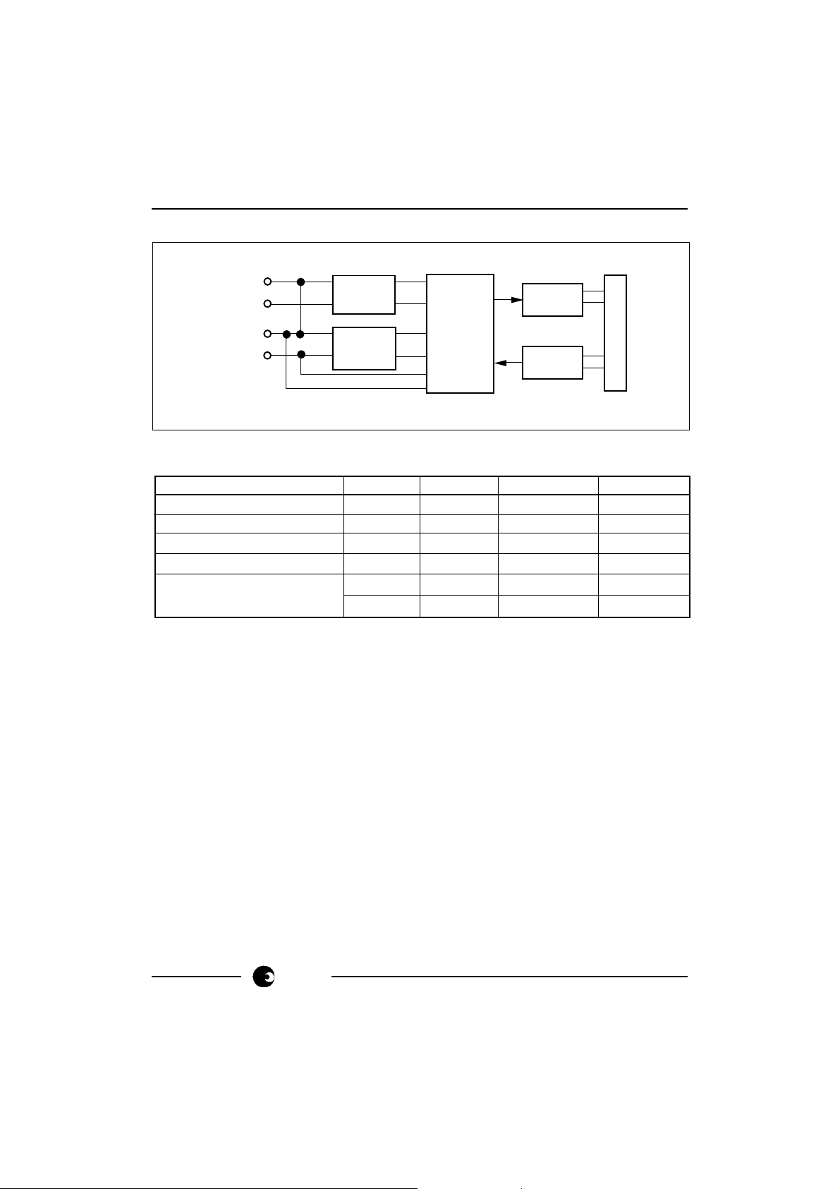
BLOCK DIAGRAM
LIVE
IN
OUT
VOL TAGE SENSE
SHUNT
POWER
SUPPLY
SA9103
SA9603
POWER
METER
DR-01448
OPTO
COUPLER
OPTO
COUPLER
D-sub CONNECTOR
NEUTRAL
NEUTRAL
NEUTRAL
ABSOLUTE MAXIMUM RATINGS*
Parameter Symbol Min Max Unit
Supply Voltage (Note 1) V
Current Sense Input (Note 1) V
Storage Temperature T
Operating Temperature T
Max Current I
through Sensor I
STG
MAX
MAX
AC
IV
-2.5 +2.5 V
-25 +125 °C
O
-10 +70 (Note 2) °C
540 V
800 (Note 3) A
2000 (Note 4) A
Note 1: Voltages are specified with reference to Live.
Note 2: The SA9103 and SA9603C integrated circuits are specified to operate over the
temperature range -10°C to +70°C. The module functionality will however
depend upon the external components used.
Note 3: t = 500ms
Note 4: t = 1ms
*Stresses above those listed under “Absolute Maximum Ratings” may cause permanent
damage to the device. This is a stress rating only. Functional operation of the device
at these or any other conditions above those indicated in the operational sections of this
specification, is not implied. Exposure to Absolute Maximum Ratings for extended
periods may affect device reliability.
2/10
sames
Page 3
PM9103AP
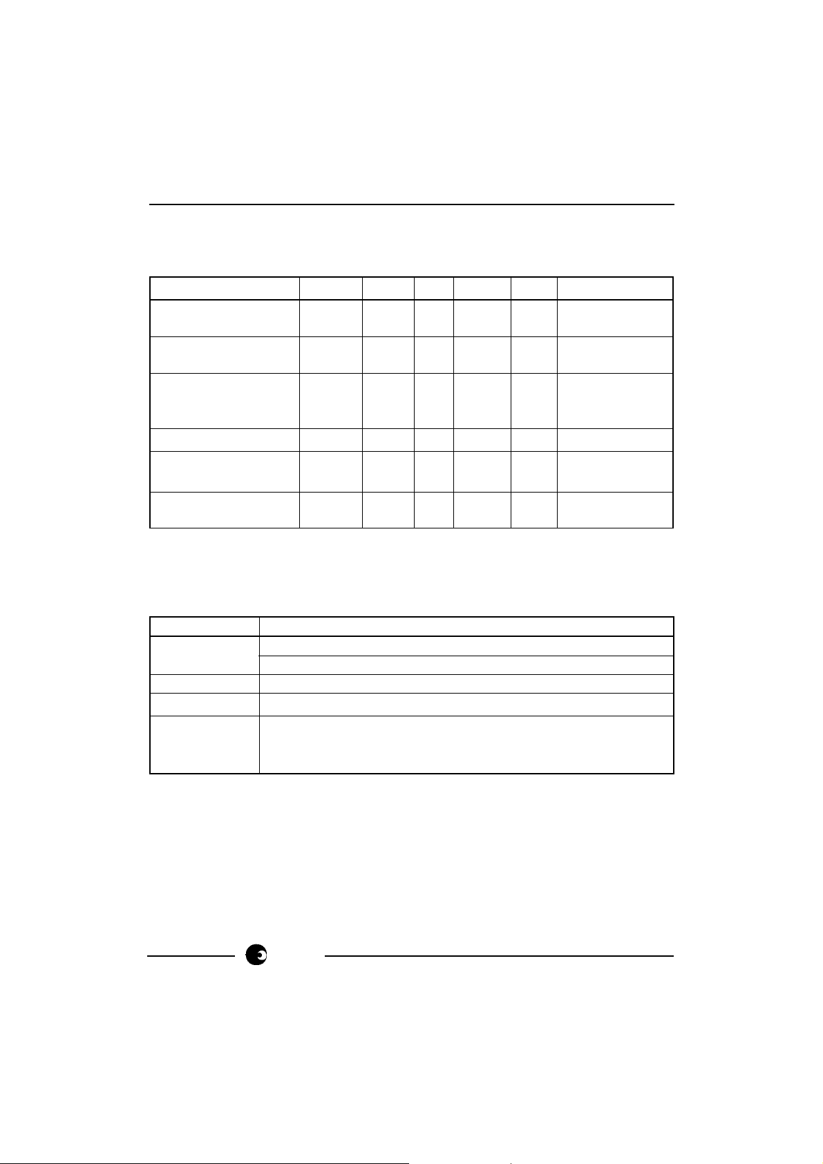
ELECTRICAL CHARACTERISTICS
(Over the temperature range -10°C to +70°C, unless otherwise specified. Power
consumption figures are applicable to the PM9103APE only.)
Parameter Symbol Min Typ Max Unit Condition
Supply Voltage V
AC
180 230 265 V PM9103APE
(Continuous) 90 115 135 V PM9103APA
Power Measurement P
RNG
-18400 18400 W Specified
range accuracy
Power Consumption
1
800 mW VAC = 230V
Supply direct
from mains
Isolation Voltage
2
V
IS
2500 V Continuous
Opto-coupler Output
Current I
O
10 mA VOL = 1V
Opto-coupler Input
Current I
I
10 mA
Note 1: Power consumption specifications exclude power consumed by the current
sensor.
Note 2: Isolation voltage may be specified, depending on customer requirements.
CONNECTION DESCRIPTION
Designation Description
MAINS
Voltage supply connection to Neutral line
Voltage supply connection to Live line
NEUTRAL IN Connection to positive side of current sensor
NEUTRAL OUT Connection to negative side of current sensor
SK1
Serial Input
D-sub connector
9-Pin
Serial Output
sames
3/10
Page 4

PM9103AP
FUNCTIONAL DESCRIPTION
1. Power Calculation
In the Application Circuit (see Figure 2), the output current from the current sensor
will be between 0 and 16µA (0 to 80A through a shunt resistor of 625µΩ). The current
input stage of the module, saturates at input currents greater than 18µA
RMS
mains voltage (Voltage + 15% - 20%) is used to supply the circuitry with power and
to perform the power calculation, together with the current information from the
current sensor (shunt resistor).
The SA9103CP, SA9103EP and SA9603C integrated circuits may be adjusted to
accommodate any voltage or current values. The method for calculating external
component values is described in paragraph 6 (Circuit Description).
SAMES offers two evaluation module options, namely 230V/80A and 115V/80A.
The calculated power is integrated into a 22 bit integrator, which is accessable via
a serial interface having a RS232 protocol. The power calculation takes the power
factor into account.
2. Electrostatic Discharge (ESD) Protection
The device's inputs/outputs are protected against ESD according to the Mil-Std
883C, method 3015. The modules resistance to transients will be dependant upon
the protection components used.
3. Power Consumption
The overall power consumption rating for this power metering application (Figure 2),
is under 500mW, excluding the current sensor, when the supply is taken directly from
the mains.
.The
4. Isolation
The serial interface is isolated from the module which is at mains potential, via two
opto-couplers. (In the event of the use of a current transformer for current sensing,
the opto-couplers would not be required.)
5. Serial Interface
Reading and resetting of the on-chip integrators may be performed using a Personel
Computer (PC). A standard serial cable should be used to connect SK1 to the PC.
The computers port settings are as follows:
19 200 Baud
1 Start bit
1 Stop bit
No parity bits
The Serial Interface allows for the following operations:
Read Integrator: The device transmits the current integrator status to the controller,
after the current measurement cycle has been completed (8 mains periods maximum).
4/10
sames
Page 5

Reset Integrator: The integrator is reset without transmitting the integrator
status.
Read/Reset Integrator: The device transmits the integrator status and resets the
integrator after the current measurement cycle has been completed.
In a typical application, the system controller monitors the status of the on-chip
integrator using the "Read" command.
If after a "Read" command, the integrator value is sufficiently high, a "Read/Reset"
command from the controller causes the integrated circuit to complete the existing
measurement cycle, transmit the 16 most significant bits of the 22 bit integrator
via the Serial Output, to the controller and restart the integrator.
The most significant bit of the 16 bits, indicates the direction of energy consumption
measured (0 = Positive, 1 = Negative).
Refer to the SA9103C, SA9103E or SA9603C datasheets for the serial interface
command protocols.
6. Circuit Description
The Application Circuit (figure 2) shows the components required for the serial
interface power metering module, using a shunt resistor for current sensing.
In this application the device requires +2.5V, 0V, -2.5V DC supply.
The most important external components are:
C1 and C2 are the outer loop capacitors of the two integrated oversampling A/D
converters. The value of these capacitors is 560pF. The actual values determine
signal to noise and stability performance. The tolerance should be within ±10%.
C3 and C4 are the inner loop capacitors of the A/D converters. The optimum value
is 3.3nF. The actual values are uncritical. Values smaller than 0.5nF and larger
than 5nF should be avoided.
R2, R1 and RSH are the resistors defining the current level into the current sense
input. The values should be selected for an input current of 16µA
into the SA9103
RMS
/ SA9603C at maximum line current.
Values for RSH of less than 200µΩ should be avoided.
R1 = R2 = IL/16µA
* RSH/2.
RMS
Where IL= Line current
RSH = Shunt resistor/terminating resistor
R3, R6 and R4 set the current for the voltage sense input. The values should be
selected so that the input current into the voltage sense input (virtual ground) is set
to 14µA
RMS
.
R7 defines all on-chip bias and reference currents. With R7 = 24kΩ, optimum
conditions are set.
sames
PM9103AP
5/10
Page 6

PM9103AP
XTAL is a colour burst TV crystal (f = 3.5795MHz) for the oscillator. The oscillator
frequency is divided down to 1.7897MHz on-chip and supplies the A/D converters
and the digital circuitry.
7. Demonstration Software
Software which runs under Windows 3.1 is provided with each evaluation module.
See README.TXT on the diskette supplied for the installation instructions.
Figure 1: Connection Diagram
6/10
sames
Page 7
PM9103AP
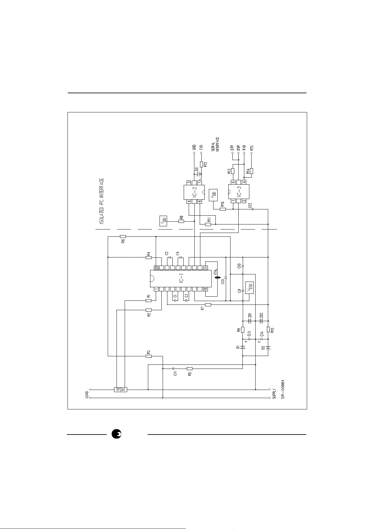
APPLICATION CIRCUIT
Figure 2: Application using a Shunt Resistor for Current Sensing, having a PC
(Personal Computer) Interface.
Note: The Serial Interface having a RS232 protocol, has been designed to operate
directly with a PC (Personal Computer).
sames
7/10
Page 8

PM9103AP
Parts List For Application Circuit: Figure 2
Item Symbol Description Detail
1 IC-1 SA9103CP/SA9103EP/SA9603C DIP-20
2 IC-2 Opto Coupler 4N35 DIP-6
3 IC-3 Opto Coupler 4N35 DIP-6
4 D1 Diode, Silicon, 1N4148
5 D2 Diode, Silicon, 1N4148
6 D3 Diode, Silicon, 1N4148
7 ZD1 Diode, Zener, 2.4V, 200mW
8 ZD2 Diode, Zener, 2.4V, 200mW
9 XTAL Crystal, 3.5795MHz Colour burst TV
10 R1 Resistor, 1.6kΩ, 1%, metal Note 1
11 R2 Resistor, 1.6kΩ, 1%, metal Note 1
12 R3A Resistor, 1%, metal Note 2
13 R3B Resistor, 1%, metal Note 2
14 R4 Resistor, 1M, ¼W
15 R5 Resistor, 470Ω, 2W, 5%, carbon
16 R6 Resistor, 24k, ¼W, metal
17 R7 Resistor, 24k, ¼W, metal
18 R8 Resistor, 680Ω, ¼W, 5%
19 R9 Resistor, 680Ω, ¼W, 5%
20 R10 Resistor, 680Ω, ¼W, 5%
21 R12 Resistor, 120Ω, ¼W, 5%
22 R13 Resistor, 120k, ¼W, 5%
23 R14 Resistor, 3.9k, ¼W, 5%
24 R15 Resistor, 120Ω, ¼W, 5%
25 C1 Capacitor, 560pF
26 C2 Capacitor, 560pF
27 C3 Capacitor, 3.3nF
28 C4 Capacitor, 3.3nF
29 C9 Capacitor, 100nF
30 C10 Capacitor, 100nF
31 C11 Capacitor, polyester Note 2
32 C12 Capacitor, 100nF
33 C13 Capacitor, 100µF, 16V
34 C14 Capacitor, 100µF, 16V
35 C15 Capacitor, 820nF, 16V
36 RSH Shunt Resistor, 80A, 50mV (625µΩ) Note 1
Note 1: Resistor (R1 and R2) values are dependant upon the selected value of RSH. See
paragraph 6 (Circuit Description) when selecting the value for RSH.
Note 2: See the table below, detailing the component values for the selected voltage standard.
8/10
sames
Page 9
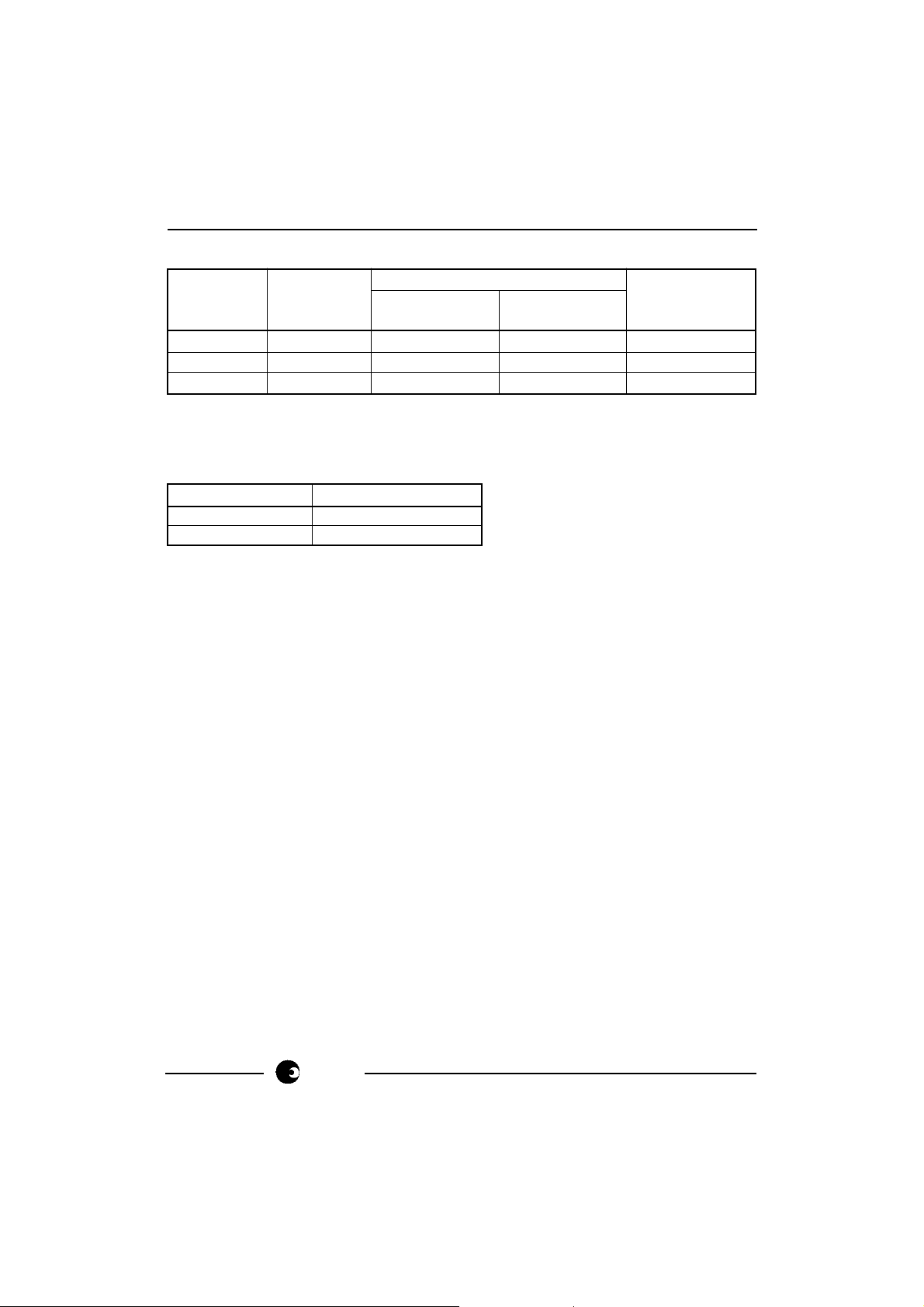
Description
Item Symbol
PM9103APA PM9103APE
115V 230V
12 R3A 120kΩ 200kΩ
13 R3B 82kΩ 180kΩ
31 C11 1µF 0.47µF
ORDERING INFORMATION
Part Number Description
PM9103APA 115V, 80A Module
PM9103APE 230V, 80A Module
PM9103AP
Detail
sames
9/10
Page 10

PM9103AP
Disclaimer: The information contained in this document is confidential and proprietary to South African Micro-
Electronic Systems (Pty) Ltd ("SAMES") and may not be copied or disclosed to a third party, in whole or in part,
without the express written consent of SAMES. The information contained herein is current as of the date of
publication; however, delivery of this document shall not under any circumstances create any implication that the
information contained herein is correct as of any time subsequent to such date. SAMES does not undertake to inform
any recipient of this document of any changes in the information contained herein, and SAMES expressly reserves
the right to make changes in such information, without notification,even if such changes would render information
contained herein inaccurate or incomplete. SAMES makes no representation or warranty that any circuit designed
by reference to the information contained herein, will function without errors and as intended by the designer.
Any Sales or technical questions may be posted to our e-mail address below:
energy@sames.co.za
For the latest updates on datasheets, please visit out web site:
http://www.sames.co.za
South African Micro-Electronic Systems (Pty) Ltd
P O Box 15888, 33 Eland Street,
Lynn East, Koedoespoort Industrial Area,
0039 Pretoria,
Republic of South Africa, Republic of South Africa
Tel: 012 333-6021 Tel: Int +27 12 333-6021
Fax: 012 333-8071 Fax: Int +27 12 333-8071
10/10
sames
 Loading...