

Page 1
PM600DVA060
Powerex, Inc., 200 Hillis Street, Youngwood, Pennsylvania 15697-1800 (724) 925-7272
AA
SQ PIN
(10 PLS)
(2 PLS)
L
RSFO
AMP
RG
T - (4 TYP.)
H
F
J
V
W
X
PO P1 PR P1
VCC
TEMP
Z
G
M
VFSC
1
A
D
Y
B
E
C2E1 E2 C1
R
S - NUTS
(3 TYP)
C
U
NC
V
43 2 5
C C
i
NI
GND
OUT2
SINK
SENS OUT1
E2
Q Q P
K K K
NR N1 NO N1
FSC
RSFO
TEMP
AMP
RG
V
CC
TH
V
1
RFO RFO
RREF
C2E1 C1
5
4
N
3
2
1
5
4
3
P
2
1
N
V
PC
43 2 5
i
NI
GND
OUT2
SENS OUT1
SINK
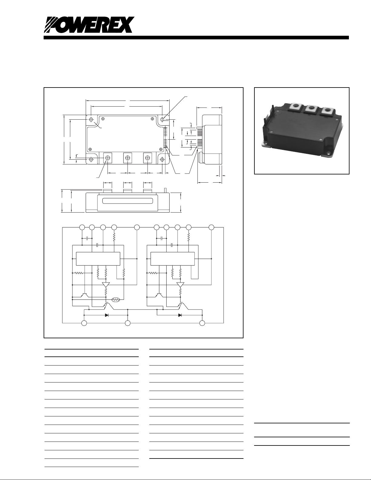
Outline Drawing and Circuit Diagram
Dimensions Inches Millimeters
A 4.72 120.0
B 3.54 90.0
C 1.34 +0.04/-0.02 34 +1.0/-0.5
D 4.17±0.010 106.0±0.25
E 2.99±0.010 76.0±0.25
F 1.52 38.5
G 0.16 4.0
H 0.16 4.01
J 0.40 10.16
K 0.71 18.0
L 1.22 31.0
M 1.73 44.0
Dimensions Inches Millimeters
P 1.22 31.0
Q 1.10 28.0
R 0.12 3.0
S M8 Metric M8
T 0.26 Dia. Dia. 6.5
U 1.29 32.8
V 0.10 2.54
W 0.025 SQ 0.64 SQ
X 0.14 Dia. 3.5 Dia.
Y 0.26 Dia. Dia. 6.5
Z 1.79 45.5
AA 1.5 38.0
N 0.12 3.0
Intellimod™ Module
Single Phase
IGBT Inverter Output
600 Amperes/600 Volts
Description:
Powerex Intellimod™ Intelligent
Power Modules are isolated base
modules designed for power
switching applications operating
at frequencies to 20kHz. Built-in
control circuits provide optimum
gate drive and protection for the
IGBT and free-wheel diode
power devices.
Features:
□ Complete Output Power
Circuit
□ Gate Drive Circuit
□ Protection Logic
– Short Circuit
– Over Temperature
– Under Voltage
Applications:
□ Inverters
□ UPS
□ Motion/Servo Control
□ Power Supplies
Ordering Information:
Example: Select the complete
part number from the table below
-i.e. PM600DVA060 is a 600V,
600 Ampere Intellimod™ Intelligent
Power Module.
Type Current Rating V
Amperes Volts (x 10)
PM 600 60
CES
413
Page 2

Powerex, Inc., 200 Hillis Street, Youngwood, Pennsylvania 15697-1800 (724) 925-7272
PM600DVA060
Intellimod™ Module
Single Phase IGBT Inverter Output
600 Amperes/600 Volts
Absolute Maximum Ratings, Tj = 25°C unless otherwise specified
Characteristics Symbol PM600DVA060 Units
Power Device Junction Temperature T
Storage T emperature T
Case Operating Temperature T
j
stg
C
-20 to 150 °C
-40 to 125 °C
-20 to 100 °C
Mounting Torque, M6 Mounting Screws (Typical) — 26 in-lb
Mounting Torque, M8 Main Terminal Screws (Typical) — 95 in-lb
Module Weight (Typical) — 720 Grams
Supply Voltage (Applied between C1-E2) V
Supply Voltage Protected by SC (VD = 13.5 ~16.5V, Inverter Part, Tj = 125°C Start) V
Isolation Voltage, AC 1 minute, 60Hz Sinusoidal V
CC(surge)
CC(prot.)
RMS
500 Volts
400 Volts
2500 Volts
Control Sector
Supply Voltage Applied between (VP1-VPC, VN1-VNC)V
Input Voltage Applied between (CP1-VPC, VN1-VNC)V
D
CIN
Fault Output Supply Voltage (Applied between FPO-VPC, FNO-VNC)VFO20 Volts
Fault Output Current (Sink Current at FO T erminals) I
FO
20 Volts
10 Volts
20 mA
IGBT Inverter Sector
Collector-Emitter Voltage (VD = 15V, V
Collector Current, ± (TC = 25°C) I
Peak Collector Current, ± (TC = 25°C) I
Collector Dissipation (TC = 25°C) P
= 5V) V
CIN
CES
C
CP
C
600 Volts
600 Amperes
1200 Amperes
1390 Watts
Electrical and Mechanical Characteristics, Tj = 25°C unless otherwise specified
Characteristics Symbol Test Conditions Min. Typ. Max. Units
Control Sector
Short Circuit Trip Level SC -20°C ≤ Tj ≤ 125°C, VD = 15V 1000 1400 — Amperes
Short Circuit Current Delay Time t
off(SC)
Over Temperature Protection OT T rip Level 100 110 120 °C
(VD = 15V, Lower Arm) OT
r
Supply Circuit Under Voltage Protection UV Trip Level 11.5 12.0 12.5 Volts
(-20°C ≤ Tj ≤ 125°C) UV
Circuit Current I
r
D
VD = 15V, V
VD = 15V, V
Input ON Threshold Voltage V
Input OFF Threshold Voltage V
Fault Output Current I
Minimum Fault Output Pulse Width t
SXR T erminal Output Voltage V
CIN(on)
CIN(off)
FO(H)
I
FO(L)
FO
SXR
Tj ≤ 125°C, Rin = 6.8kΩ (SPR, SNR) 4.5 5.1 5.6 Volts
VD = 15V — 10 — µS
Reset Level 85 95 105 °C
Reset Level — 12.5 — Volts
= 5V, VN1-V
CIN
= 5V, VP1-V
CIN
NC
PC
— 23 30 mA
— 23 30 mA
Applied between 1.2 1.5 1.8 Volts
CP1-VPC, CN1-V
NC
1.7 2.0 2.3 Volts
VD = 15V, VFO = 15V ——0.01 mA
VD = 15V, VFO = 15V — 10 15 mA
VD = 15V 1.0 1.8 — mS
414
Page 3

Powerex, Inc., 200 Hillis Street, Youngwood, Pennsylvania 15697-1800 (724) 925-7272
PM600DVA060
Intellimod™ Module
Single Phase IGBT Inverter Output
600 Amperes/600 Volts
Electrical and Mechanical Characteristics, Tj = 25°C unless otherwise specified
Characteristics Symbol Test Conditions Min. Typ. Max. Units
IGBT Inverter Sector
Collector-Emitter Cutoff Current I
FWDi Forward Voltage V
Collector-Emitter Saturation Voltage V
Inductive Load Switching Times t
CES
EC
CE(sat)
on
t
rr
t
C(on)
t
off
t
C(off)
VCE = V
VCE = V
-IC = 600A, VD = 15V, V
VD = 15V, V
, VD = 15V, Tj = 25°C ——1.0 mA
CES
, VD = 15V, Tj = 125°C ——10.0 mA
CES
= 5V — 2.20 3.30 Volts
CIN
= 0V, IC = 600A, — 2.35 2.80 Volts
CIN
Pulsed, Tj = 25°C
VD = 15V, V
= 0V, IC = 600A, — 2.55 3.05 Volts
CIN
Pulsed, Tj = 125°C
0.5 1.4 2.5 µS
VD = 15V, V
= 0V ~ 5V — 0.15 0.3 µS
CIN
VCC = 300V, IC = 600A, — 0.4 1.0 µS
Tj = 125°C — 2.0 3.0 µS
— 0.5 1.0 µS
Thermal Characteristics
Characteristic Symbol Condition Min. Typ. Max. Units
Junction to Case Thermal Resistance R
R
Contact Thermal Resistance R
th(j-c)Q
th(j-c)D
th(c-f)
Each Inverter IGBT ——0.09 °C/Watt
Each Inverter FWDi ——0.13 °C/Watt
Case to Fin Per Module, ——0.065 °C/Watt
Thermal Grease Applied
Recommended Conditions for Use
Characteristic Symbol Condition Value Units
Supply Voltage V
V
CE(surge)
Input ON Voltage V
Input OFF Voltage V
Arm Shoot-Through Blocking Time t
CC
V
D
CIN(on)
CIN(off)
DEAD
Applied across C1-E2 Terminals ≤ 400 Volts
Applied across C1-E1, C2-E2 Terminals ≤ 500 Volts
Applied between 15 ± 1.5 Volts
VP1-VPC, VN1-V
NC
Applied between ≤ 0.8 Volts
CP1-VPC, CN1-V
NC
≥ 4.0 Volts
For IPM's each Input Signal ≥ 3.5 µS
415
Page 4

Powerex, Inc., 200 Hillis Street, Youngwood, Pennsylvania 15697-1800 (724) 925-7272
PM600DVA060
Intellimod™ Module
Single Phase IGBT Inverter Output
600 Amperes/600 Volts
SATURATION VOLTAGE CHARACTERISTICS
(TYPICAL)
6
, (VOLTS)
5
CE(SAT)
4
3
2
t
c(on)
VD = 15V
2
10
1
COLLECTOR-EMITTER VOLTAGE, V
0
0 200 400 600100 300 500
COLLECTOR CURRENT, IC, (AMPERES)
SWITCHING TIME VS.
COLLECTOR CURRENT (TYPICAL)
1
10
VCC = 300V
V
= 15V
D
= 25°C
T
, (µs)
c(off)
, t
c(on)
t
0
10
SWITCHING TIMES,
-1
10
10
j
T
= 125°C
j
1
COLLECTOR CURRENT, IC, (AMPERES)
Tj = 25°C
= 125°C
T
j
t
c(off)
SATURATON VOLTAGE CHARACTERISTICS
COLLECTOR-EMITTER
(TYPICAL)
6
1
10
SWITCHING TIME VS.
COLLECTOR CURRENT (TYPICAL)
5
, (µs)
4
, (VOLTS)
3
CE(SAT)
V
2
SW(off)
SW(on)
IC = 600A
Tj = 25°C
= 125°C
T
j
1
COLLECTOR-EMITTER SATURATION VOLTAGE,
0
0 131517
CONTROL SUPPLY VOLTAGE, VD, (VOLTS)
SWITCHING LOSS
CHARACTERISTICS (TYPICAL)
2
10
VCC = 300V
V
= 15V
D
, (mJ/PULSE)
SW(off)
, P
10
SW(on)
SWITCHING ENERGY, P
3
10
10
Tj = 25°C
= 125°C
T
j
1
P
P
0
1 102 103
10
COLLECTOR CURRENT, IC, (AMPERES)
off
, t
on
0
10
SWITCHING TIMES, t
-1
10
2
10
COLLECTOR CURRENT, IC, (AMPERES)
FWDi REVERSE RECOVERY CURRENT VS.
COLLECTOR CURRENT (TYPICAL)
0
10
, (µS)
rr
-1
10
t
off
t
on
I
t
10
rr
rr
VCC = 300V
V
3
VCC = 300V
REVERSE RECOVERY TIME, t
-2
10
2 103 104
10
COLLECTOR CURRENT, IE, (AMPERES)
V
= 15V
D
= 15V
D
Tj = 25°C
= 125°C
T
j
Tj = 25°C
= 125°C
T
j
4
10
0
10
, (AMPERES)
rr
1
10-
-2
REVERSE RECOVERY CURRENT, I
10
3
10
, (AMPERES)
E
2
10
DIODE FORWARD CURRENT, I
1
10
0 1.0 2.0 3.0
416
DIODE FORWARD CHARACTERISTICS
VD = 15V
Tj = 25°C
= 125°C
T
j
DIODE FORWARD VOLTAGE, VEC, (VOLTS)
 Loading...