

Page 1

PRODUCTION
DATASHEET
PMC-1981162 ISSUE 6 SONET/SDH PAYLOAD EXTRACTOR/ALIGNER FOR 622 MBIT/S
PMC-Sierra, Inc.
PM5313 SPECTRA-622
PM5313
SPECTRA-622
SONET/SDH PAYLOAD
EXTRACTOR/ALIGNER
FOR 622 MBIT/S
DATA SHEET
PROPRIET A RY AND CONFIDENTIAL
PRODUCTION
ISSUE 6: SEPTEMBER 2000
PMC-Sierra, Inc. 105 - 8555 Baxter Place Burnaby, BC Canada V5A 4V7 604 .415.6000
Page 2
PRODUCTION
DATASHEET
PMC-1981162 ISSUE 6 SONET/SDH PAYLOAD EXTRACTOR/ALIGNER FOR 622 MBIT/S
PMC-Sierra, Inc.
PM5313 SPECTRA-622
Issue No. Issue Date Details of Change
Issue 6 Sept 2000
Issue 5 May 2000
• Remove support of in-band G1 reporting on
DROP bus
• Improve RAD Timing diagram (Fig 60)
• Pointer justification not generated in PAIS on
DROP bus
• Specify that the jitter tolerance is according to the
1995 Bellcore spec.
• Remove the K1 and K2 bytes from the RAD.
• Specify that a RESET_PATH command will also
clear the performing monitor counters of the
section/line TSBs.Update AC and DC
Characeristic sections according to its final
report..
• V1 pulse is always outputted on the DROP bus
when the RTAL FIFO is bypassed
• Add the RESET sequence to enable the TX line
interface and the OUTDATA bit in the CRSI.
• Specify TFPO timing in serial mode
• CRU and CSU will track REFCLK while in ROOL
• Describe RX and TX bypass mode limitations
• SDLE and RBYP mode can not be set at the
same time.
• Fix number of bits before a DOOL is declared
from 80 to 96.
• Bit 7 of register 0090H is now X vs 0.
• Write to the PMON c ounter registers will also
trigger a count transfer.
• SS bits are always 00 when the DPGM is in
autonomous mode.
• Add WANS programming section
• Update the RAD and TFPI timing diagrams.
• Update rev of CRU, GPGM and TTOC.
• Update the methodology Tools table.
• Added STM1-CONCAT register bits in RPPS and
TPPS configuration.
• Extend the timing for output pins RSUC, RSOW,
ROH and TDO.
PROPRIETARY AND CONFIDENTIAL i
Page 3

PRODUCTION
DATASHEET
PMC-1981162 ISSUE 6 SONET/SDH PAYLOAD EXTRACTOR/ALIGNER FOR 622 MBIT/S
PMC-Sierra, Inc.
PM5313 SPECTRA-622
• Remove support for the tandem connection
• Removed RESBYP and TESBYPASS register bits
in RPPS and TPPS configuration. Bypass is no
longer programmable per slice but for all RPPS or
TPPS slices via the RESBYP and TESBYP bits
found in DROP and ADD BUS configuration
registers.
• Fix RASE filtering spec to 8 frames
• Correct DLL, APGM and DPGM register bits
description
• Describe use of ATSI bit in APGM autonomous
mode.
• Remove support of 12c when both autonomous
mode and DTMODE are use.
• Specify that FOOF affect only one frame
• Add TS
DC spec.
TAD
• Add power supply filtering and PECL I/O
diagrams
• Revise RPOH timing diagrams
• Add BYPASS Rx and TX mode description and
limitation. No support for TUAIS, tx dual mode
and pointer generation by STALs.
• Specify that activity on the AC1J1V1, ADP and
APL pins can not be detected if ADP is tied high
or low.
Issue 4
• Revised RPPS alarm bit names, register 0n1C
• Revised National bit description in the TTOC
register 00C1
• Revised signal mapping in register 0009
SPECTRA 622 Section Alarm Control #2
• Added pin description of the Transmit Ring
Control Port
• Fixed polarity for bit 7, register 0102
• Added TPIP is held in reset in DS3 mode only
• Revised TPAIS and DPAIS frame slots to correctly
correspond to slice order
• Clarified precedence of TOH Overhead port over
TSOW , TSUC , and TLOW
• Removed some DLL registers
PROPRIETARY AND CONFIDENTIAL ii
Page 4

PRODUCTION
DATASHEET
PMC-1981162 ISSUE 6 SONET/SDH PAYLOAD EXTRACTOR/ALIGNER FOR 622 MBIT/S
PMC-Sierra, Inc.
PM5313 SPECTRA-622
• ADD DLL does not exist
• Clarified description of SSTB/SPTB write trigger
register
• Revised TTOH, TTOHEN set-up time
• Clarified SENB bit description in register 0030
• Clarified bit DC1 description in register 00B4
• Clarified APGM/DPGM register information
• Clarified register 1102 description
• BIP calculation not supported by TPIP
• Added REFCLK required when generating
DS3ROCLK internally
• Added pin description for FPIN and TPL
• Revised RASE description and register definitions
• Revised bit 6 Path Reset description, register
0000
• Clarified Protection Switch Byte Failures detection
description
• Added updates based on preps
• Remove STS-6c/9c support
• Fix register bits definitions
• Fix Tx Ring Control Port definiton
• Remove B3 verification from ADD bus
• Revised Recommended BERM settings
Issue 3 July 1999
• Added FPPOS bit in register 0003
• Added Register 0016
• Added SCPII bit in register 000B
• Uncovered EXT bit in register 1151
• Added pin number
• Added boundary scan chain information
Issue 2 April 1999
• Removed DS-3 framers
• Block diagram updated
• TTOC and RTOC registers added
• Swapped RASE and SSTB register blocks
Issue 1 Sep 1998 Document created
PROPRIETARY AND CONFIDENTIAL iii
Page 5

PRODUCTION
DATASHEET
PMC-1981162 ISSUE 6 SONET/SDH PAYLOAD EXTRACTOR/ALIGNER FOR 622 MBIT/S
PMC-Sierra, Inc.
PM5313 SPECTRA-622
CONTENTS
1 FEATURES.....................................................................................1
1.1 GENERAL............................................................................1
1.2 SONET SECTION AND LINE / SDH REGENERATOR
AND MULTIPLEXER SECTION...........................................2
1.3 SONET PATH / SDH HIGH ORDER PATH...........................3
1.4 SYSTEM SIDE INTERFACES..............................................4
2 APPLICATIONS ..............................................................................6
3 REFERENCES................................................................................7
4 DEFINITIONS................................................................................. 8
5 APPLICATION EXAMPLES ............................................................ 9
6 BLOCK DIAGRAM........................................................................14
7 LOOPBACK MODES....................................................................15
8 DESCRIPTION..............................................................................16
9 PIN DIAGRAMS............................................................................ 18
10 PIN DESCRIPTION (520).............................................................23
10.1 SERIAL LINE SIDE INTERFACE SIGNALS....................... 23
10.2 PARALLEL LINE SIDE INTERFACE SIGNALS.................. 26
10.3 RECEIVE AND TRANSMIT CLOCKS ................................31
10.4 SECTION/LINE STATUS AND ALARMS SIGNALS...........35
10.5 RECEIVE TRANSPORT OVERHEAD EXTRACTION
SIGNALS............................................................................ 42
10.6 TRANSMIT TRANSPORT OVERHEAD INSERTION
SIGNALS............................................................................ 49
PROPRIETARY AND CONFIDENTIAL iv
Page 6

PRODUCTION
DATASHEET
PMC-1981162 ISSUE 6 SONET/SDH PAYLOAD EXTRACTOR/ALIGNER FOR 622 MBIT/S
PMC-Sierra, Inc.
PM5313 SPECTRA-622
10.7 RECEIVE PATH STATUS AND OVERHEAD SIGNAL ....... 57
10.8 TRANSMIT PATH OVERHEAD SIGNALS..........................63
10.9 DROP AND TRANSMIT P A TH AIS CONTROL
SIGNALS............................................................................ 66
10.10 DROP BUS INTERFACE CONFIGURATION..................... 69
10.11 DROP BUS TELECOM INTERFACE SIGNALS.................70
10.12 ADD BUS TELECOM INTERFACE SIGNALS....................81
10.13 DS3 SYSTEM SIDE INTERFACE...................................... 95
10.14 MICROPROCESSOR INTERFACE SIGNALS...................97
10.15 ANALOG MISCELLANEOUS SIGNALS .......................... 100
10.16 JTAG TEST ACCESS PORT (TAP) SIGNALS.................. 101
10.17 POWER AND GROUND...................................................102
11 FUNCTIONAL DESCRIPTION.................................................... 107
11.1 RECEIVE LINE INTERFACE............................................ 107
11.1.1 CLOCK RECOVERY UNIT.................................... 107
11.1.2 SERIAL TO PARALLEL CONVERTER.................. 109
11.2 RECEIVE SECTION OVERHEAD PROCESSOR
(RSOP)............................................................................. 109
11.3 RECEIVE SECTION TRACE BUFFER (SSTB).................110
11.4 RECEIVE LINE OVERHEAD PROCESSOR (RLOP)........ 111
11.5 RECEIVE TRANSPORT OVERHEAD CONTROLLER
(RTOC)..............................................................................113
11.6 RING CONTROL PORT....................................................113
11.7 RECEIVE PATH PROCESSING SLICE (RPPS)...............114
PROPRIETARY AND CONFIDENTIAL v
Page 7

PRODUCTION
DATASHEET
PMC-1981162 ISSUE 6 SONET/SDH PAYLOAD EXTRACTOR/ALIGNER FOR 622 MBIT/S
PMC-Sierra, Inc.
PM5313 SPECTRA-622
11.7.1 RECEIVE PATH OVERHEAD PROCESSOR
(RPOP)...................................................................116
11.7.2 RECEIVE PATH TRACE BUFFER (SPTB)............ 122
1 1.7.3 RECEIVE TELECOMBUS ALIGNER (RTAL)......... 124
11.7.4 DS3 MAPPER DROP SIDE (D3MD) ..................... 129
11.7.5 DROP BUS PRBS GENERATOR AND
MONITOR (DPGM)................................................132
11.8 TRANSMIT PATH PROCESSING SLICE (TPPS)............ 134
11.8.1 ADD BUS PRBS GENERATOR AND
MONITOR (APGM)................................................ 136
11.8.2 DS3 MAPPER ADD SIDE (D3MA).........................136
11.8.3 TRANSMIT POINTER INTERPRETER
PROCESSOR (TPIP) ............................................ 138
1 1.8.4 TRANSMIT TELECOMBUS ALIGNER (TTAL) ......139
11.8.5 TRANSMIT PATH TRACE BUFFER (SPTB) ......... 140
11.8.6 T RANSMIT PATH OVERHEAD PROCESSOR
(TPOP) ..................................................................141
1 1.9 TRANSMIT TRANSPORT OVERHEAD
CONTROLLER (TTOC).................................................... 142
11.10 TRANSMIT LINE OVERHEAD PROCESSOR (TLOP).....144
11.11 TRANSMIT SECTION OVERHEAD PROCESSOR
(TSOP)............................................................................. 145
11.12 TRANSMIT SECTION TRACE BUFFER (SSTB)............. 145
11.13 TRANSMIT LINE INTERFACE.........................................146
11.13.1...................................................CLOCK SYNTHESIS 146
1 1. 13.2........................PARALLEL T O SERIAL CONVERTER 146
11.14 WAN SYNCHRONIZATION CONTROLLER (WANS) ......147
PROPRIETARY AND CONFIDENTIAL vi
Page 8

PRODUCTION
DATASHEET
PMC-1981162 ISSUE 6 SONET/SDH PAYLOAD EXTRACTOR/ALIGNER FOR 622 MBIT/S
PMC-Sierra, Inc.
PM5313 SPECTRA-622
11.15 ADD/DROP BUS TIME-SLOT INTERCHANGE (TSI) ...... 150
11.16 SYSTEM SIDE INTERFACES..........................................151
11.16.1.......................................TELECOMBUS INTERFACE 151
11.16.2........................................... SERIAL DS3 INTERFACE 153
11.17 JTAG TEST ACCESS PORT INTERFACE....................... 153
11.18 MICROPROCESSOR INTERFACE ................................. 154
12 NORMAL MODE REGISTER DESCRIPTION ............................ 166
13 TEST FEATURES DESCRIPTION..............................................474
13.1 MASTER TEST AND TEST CONFIGURA TION
REGISTERS.....................................................................474
13.2 JT AG TEST PORT ...........................................................479
13.2.1BOUNDARY SCAN CELLS................................... 486
14 OPERATION...............................................................................489
14.1 SOFTWARE INITIALIZATION SEQUENCE.....................489
14.2 TRANSPORT AND PATH OVERHEAD BYTES............... 489
14.3 LINE CONFIGURATION OPTIONS ................................. 495
14.3.1 STS-12/12 C (STM-4/AU3/AU4/A U4-XC)
MODE.................................................................... 495
14.4 PATH PROCESSING SLICE CONFIGURATION
OPTIONS......................................................................... 495
14.4.1BASIC CONFIGURATION..................................... 495
14.4.2 ADDITIONAL CONFIGURATION FOR
TRANSMIT CONCATENATED STREAM
SUPPORT............................................................. 498
14.4.3 CONCATENATED AND NON-
CONCATENATED STREAMS DETECTION.......... 498
PROPRIETARY AND CONFIDENTIAL vii
Page 9

PRODUCTION
DATASHEET
PMC-1981162 ISSUE 6 SONET/SDH PAYLOAD EXTRACTOR/ALIGNER FOR 622 MBIT/S
PMC-Sierra, Inc.
PM5313 SPECTRA-622
14.4.4 PRB S GENERATOR/MONITOR
CONFIGURATION FOR CONCATENATED
STREAMS............................................................. 499
14.5 TIME SLOT INTERCHANGE (GROOMING)
CONFIGURATION OPTIONS .......................................... 500
14.6 SYSTEM INTERFACE CONFIGURATION OPTIONS...... 501
14.6.1SINGLE 77.76 MHZ BYTE TELECOM BUS
MODE.................................................................... 501
14.6.2FOUR 19.44 MHZ BYTE TELECOM BUS
MODE.................................................................... 501
14.6.3SERIAL DS3 MODE..............................................502
14.6.4DROP BUS MODE................................................ 502
14.7 BIT ERROR RATE MONITOR.......................................... 503
14.8 CLOCKING OPTIONS ..................................................... 504
14.9 WAN SYNCHRONIZATION PARAMETERS.................... 505
14.9.1PLL GAIN...............................................................506
14.9.2PHASE COMPARATOR ........................................ 507
14.9.3PHASE SAMPLE AVERAGING.............................507
14.9.4IMPLEMENTATION EXAMPLE .............................508
14.10 LOOPBACK OPERATION................................................508
14.11 JTAG SUPPORT.............................................................. 509
14.11.1....................................................TAP CONTROLLER 511
14.11.2.......................................................................STATES 513
14.11.3......................................................... INSTRUCTIONS 514
14.12 BOARD DESIGN RECOMMENDATIONS........................515
14.13 POWER SUPPLIES......................................................... 516
PROPRIETARY AND CONFIDENTIAL viii
Page 10

PRODUCTION
DATASHEET
PMC-1981162 ISSUE 6 SONET/SDH PAYLOAD EXTRACTOR/ALIGNER FOR 622 MBIT/S
PMC-Sierra, Inc.
PM5313 SPECTRA-622
14.14 INTERFACING TO ECL OR PECL DEVICES.................. 519
14.15 CLOCK RECOVERY........................................................ 521
15 FUNCTIONAL TIMING................................................................522
15.1 PARALLEL LINE INTERFACE.......................................... 522
15.2 RECEIVE TRANSPORT OVERHEAD EXTRACTION......525
15.2.1RECEIVE TRANSPORT OVERHEAD (RTOH)
FUNCTIONAL TIMING .......................................... 525
15.2.2 RECEIVE SECTION AND LINE DCC
FUNCTIONAL TIMING .......................................... 526
15.2.3 RECEIVE ORDER WIRE AND USER
CHANNEL FUNCTIONAL OUTPUT TIMING.........528
15.2.4 RE CEIVE OVERHEAD (ROH) FUNCTIONAL
OUTPUT TIMINGS................................................ 530
15.3 TRANSMIT TRANSPORT OVERHEAD INSERTION....... 532
15.3.1TRANSMIT TRANSPORT OVERHEAD
(TTOH) FUNCTIONAL TIMING ............................. 532
15.3.2 TRANSMIT SECTION AND LINE DCC
FUNCTIONAL TIMING .......................................... 533
15.3.3 TRANSMIT ORDER WIRE AND USER
CHANNEL FUNCTIONAL TIMING ........................ 536
15.3.4 TRANSMIT OVERHEAD (TOH) FUNCTIONAL
TIMING.................................................................. 537
15.4 PATH OVERHEAD EXTRACTION AND INSERTION ......540
15.5 MATE SPECTRA-622 INTERFACES............................... 544
15.6 TELECOM BUS SYSTEM SIDE....................................... 549
15.6.1DROP BUS............................................................549
15.6.2ADD BUS ............................................................... 556
PROPRIETARY AND CONFIDENTIAL ix
Page 11

PRODUCTION
DATASHEET
PMC-1981162 ISSUE 6 SONET/SDH PAYLOAD EXTRACTOR/ALIGNER FOR 622 MBIT/S
PMC-Sierra, Inc.
PM5313 SPECTRA-622
15.7 DS3 MODE SYSTEM SIDE..............................................566
15.8 SYSTEM SIDE PATH AND DS3 AIS CONTROL
PORT ............................................................................... 567
16 ABSOLUTE MAXIMUM RATINGS.............................................. 570
17 D.C. CHARACTERISTICS.......................................................... 571
18 MICROPROCESSOR INTERFACE TIMING
CHARACTERISTICS..................................................................575
19 A.C. TIMING CHARACTERISTICS............................................. 582
19.1 SYSTEM RESET TIMING ................................................ 582
19.2 PARALLEL LINE INTERFACE TIMING............................583
19.3 SERIAL LINE INTERFACE TIMING ................................. 586
19.4 RECEIVE TIMING............................................................ 588
19.5 DROP BUS TIMING......................................................... 592
19.6 P A TH AIS INPUT TIMING................................................. 597
19.7 ADD BUS TIMING............................................................ 599
19.8 TRANSMIT TIMING..........................................................602
19.9 JT AG TIMING...................................................................608
20 ORDERING AND THERMAL INFORMATION............................. 610
21 MECHANICAL INFORMATION................................................... 612
PROPRIETARY AND CONFIDENTIAL x
Page 12

PRODUCTION
DATASHEET
PMC-1981162 ISSUE 6 SONET/SDH PAYLOAD EXTRACTOR/ALIGNER FOR 622 MBIT/S
PMC-Sierra, Inc.
PM5313 SPECTRA-622
LIST OF REGISTERS
REGISTER 0000H: SPECTRA-622 RESET, IDENTITY AND
ACCUMULA TION TRIG GER...................................................... 167
REGISTER 0001H: SPECTRA-622 LINE ACTIVITY MONITOR ........... 169
REGISTER 0002H: SPECTRA-622 LINE CONFIGURATION #1 ..........171
REGISTER 0003H: SPECTRA-622 LINE CONFIGURATION #2 ..........174
REGISTER 0004H: SPECTRA-622 CLOCK CONTROL.......................176
REGISTER 0005H: SPECTRA-622 RECEIVE LINE AIS CONTROL ....178
REGISTER 0006H: SPECTRA-622 RING CONTROL ..........................180
REGISTER 0007H: SPECTRA-622 LINE RDI CONTROL.................... 182
REGISTER 0008H: SPECTRA-622 SECTION ALARM OUTPUT
CONTROL #1..............................................................................184
REGISTER 0009H: SPECTRA-622 SECTION ALARM OUTPUT
CONTROL #2..............................................................................186
REGISTER 000BH: SPECTRA-622 SECTION/LINE BLOCK
INTERRUPT STATUS................................................................. 187
REGISTER 000CH: SPECTRA-622 AUXILIARY SECTION/LINE
INTERRUPT ENABLE ................................................................189
REGISTER 000DH: SPECTRA-622 AUXILIARY SECTION/LINE
INTERRUPT STATUS................................................................. 191
REGISTER 000EH: SPECTRA-622 AUXILIARY SIGNAL
INTERRUPT ENABLE ................................................................193
REGISTER 000FH: SPECTRA-622 AUXILIARY SIGNAL
STATUS/INTERRUPT STATUS .................................................. 194
REGISTER 0010H: SPECTRA-622 PATH PROCESSING SLICE
INTERRUPT STATUS #1............................................................ 195
PROPRIETARY AND CONFIDENTIAL xi
Page 13

PRODUCTION
DATASHEET
PMC-1981162 ISSUE 6 SONET/SDH PAYLOAD EXTRACTOR/ALIGNER FOR 622 MBIT/S
PMC-Sierra, Inc.
PM5313 SPECTRA-622
REGISTER 0011H: SPECTRA-622 PATH PROCESSING SLICE
INTERRUPT STATUS #2............................................................ 195
REGISTER 0012H: SPECTRA-622 PATH PROCESSING SLICE
INTERRUPT STATUS #3............................................................ 195
REGISTER 0013H: SPECTRA-622 TRANSMIT TELECOM BUS
CONFIGURATION...................................................................... 197
REGISTER 0014H: SPECTRA-622 SERIAL CONTROL PORT
ST A TUS AND CONTROL............................................................ 199
REGISTER 0015H: SPECTRA-622 SERIAL CONTROL PORT
INTERRUPT ENABLE ................................................................200
REGISTER 0016H: SPECTRA-622 SERIAL CONTROL PORT
INTERRUPT STATUS................................................................. 201
REGISTER 0030H: CRSI CONFIGURATION AND INTERRUPT.......... 202
REGISTER 0031H: CRSI STATUS........................................................ 204
REGISTER 0032H: CRSI CLOCK RECOVERY CONTROL .................. 206
REGISTER 0033H: CRSI CLOCK TRAINING CONFIGURATION ........ 207
REGISTER 0034H: RSOP CONTROL AND INTERRUPT ENABLE......208
REGISTER 0035H: RSOP STATUS AND INTERRUPT ........................ 210
REGISTER 0036H: RSOP SECTION BIP (B1) ERROR COUNT #1.....212
REGISTER 0040H: RLOP CONTROL AND STATUS............................ 213
REGISTER 0041H: RLOP INTERRUPT ENABLE AND STATUS..........216
REGISTER 0042H: RLOP LINE BIP (B2) ERROR COUNT #1 ............. 218
REGISTER 0045H: RLOP REI ERROR COUNT #1.............................. 220
REGISTER 0050H: SSTB SECTION TRACE CONTROL..................... 222
REGISTER 0051H: SSTB SECTION TRACE STATUS......................... 225
REGISTER 0052H: SSTB SECTION TRACE INDIRECT ADDRESS.... 227
PROPRIETARY AND CONFIDENTIAL xii
Page 14

PRODUCTION
DATASHEET
PMC-1981162 ISSUE 6 SONET/SDH PAYLOAD EXTRACTOR/ALIGNER FOR 622 MBIT/S
PMC-Sierra, Inc.
PM5313 SPECTRA-622
REGISTER 0053H: SSTB SECTION TRACE INDIRECT DATA............228
REGISTER 0056H: SSTB SECTION TRACE OPERATION..................229
REGISTER 0060H: RASE INTERRUPT ENABLE................................. 230
REGISTER 0061H: RASE INTERRUPT STATUS ................................. 231
REGISTER 0062H: RASE CONFIGURATION/CONTROL....................233
REGISTER 0063H: RASE SF ACCUMULATION PERIOD.................... 235
REGISTER 0066H: RASE SF SATURATION THRESHOLD.................237
REGISTER 0068H: RASE SF DECLARING THRESHOLD................... 238
REGISTER 006AH: RASE SF CLEARING THRESHOLD..................... 239
REGISTER 006CH: RASE SD ACCUMULATION PERIOD................... 240
REGISTER 006FH: RASE SD SATURATION THRESHOLD.................242
REGISTER 0071H: RASE SD DECLARING THRESHOLD.................. 243
REGISTER 0073H: RASE SD CLEARING THRESHOLD..................... 244
REGISTER 0075H: RASE RECEIVE K1...............................................245
REGISTER 0076H: RASE RECEIVE K2...............................................246
REGISTER 0077H: RASE RECEIVE Z1/S1.......................................... 247
REGISTER 0080H: WANS CONFIGURATION......................................248
REGISTER 0081H: WANS INTERRUPT AND STATUS........................ 249
REGISTER 0082H: WANS PHASE WORD LSB................................... 250
REGISTER 0089H: WANS REFERENCE PERIOD LSB....................... 252
REGISTER 008BH: WANS PHASE COUNTER PERIOD LSB.............. 253
REGISTER 008DH: WANS PHASE AVERAGE PERIOD...................... 254
REGISTER 0090H: RTOC OVERHEAD CONTROL.............................255
PROPRIETARY AND CONFIDENTIAL xiii
Page 15

PRODUCTION
DATASHEET
PMC-1981162 ISSUE 6 SONET/SDH PAYLOAD EXTRACTOR/ALIGNER FOR 622 MBIT/S
PMC-Sierra, Inc.
PM5313 SPECTRA-622
REGISTER 0091H: RTOC AIS CONTROL............................................257
REGISTER 00A2H: TRANSMIT DLL RESET REGISTER..................... 258
REGISTER 00A3H: TRANSMIT DLL CONTROL STATUS....................258
REGISTER 00A4H: DROP BUS DLL CONFIGURATION...................... 259
REGISTER 00A6H: DROP BUS DLL RESET REGISTER.................... 261
REGISTER 00A7H: DROP BUS DLL CONTROL STATUS....................262
REGISTER 00B0H: CSPI CONFIGURATION .......................................264
REGISTER 00B1H: CSPI STATUS........................................................265
REGISTER 00B4H: TSOP CONTROL .................................................. 266
REGISTER 00B5H: TSOP DIAGNOSTIC.............................................. 267
REGISTER 00B8H: TLOP CONTROL................................................... 268
REGISTER 00B9H: TLOP DIAGNOSTIC.............................................. 269
REGISTER 00BAH: TLOP TRANSMIT K1............................................ 270
REGISTER 00BBH: TLOP TRANSMIT K2............................................ 271
REGISTER 00C0H: TTOC TRANSMIT OVERHEAD OUTPUT
CONTROL .................................................................................. 272
REGISTER 00C1H: TT OC TRANSMIT OVERHEAD BYTE
CONTROL .................................................................................. 274
REGISTER 00C2H: TTOC TRANSMIT Z0 ............................................ 277
REGISTER 00C3H: TTOC TRANSMIT S1............................................ 278
REGISTER 0100H: SPECTRA-622 RPPS CONFIGURATION .............279
REGISTER 0102H: SPECTRA-622 RPPS PATH AND DS3
CONFIGURATION...................................................................... 281
REGISTER 0110H: SPECTRA-622 RPPS PATH/DS3 AIS
CONTROL #1..............................................................................283
PROPRIETARY AND CONFIDENTIAL xiv
Page 16

PRODUCTION
DATASHEET
PMC-1981162 ISSUE 6 SONET/SDH PAYLOAD EXTRACTOR/ALIGNER FOR 622 MBIT/S
PMC-Sierra, Inc.
PM5313 SPECTRA-622
REGISTER 0111H: SPECTRA-622 RPPS PATH/DS3 AIS
CONTROL #2..............................................................................285
REGISTER 0114H: SPECTRA-622 RPPS PATH REI/RDI
CONTROL #1..............................................................................287
REGISTER 0115H: SPECTRA-622 RPPS PATH REI/RDI
CONTROL #2..............................................................................289
REGISTER 0118H: SPECTRA-622 RPPS PATH ENHANCED RDI
CONTROL #1..............................................................................291
REGISTER 0119H: SPECTRA-622 RPPS PATH ENHANCED RDI
CONTROL #2..............................................................................294
REGISTER 011CH: SPECTRA-622 RPPS RALM OUTPUT
CONTROL #1..............................................................................296
REGISTER 011DH: SPECTRA-622 RPPS RALM OUTPUT
CONTROL #2..............................................................................298
REGISTER 0128H: SPECTRA-622 RPPS PATH/DS3 INTERRUPT
STATUS ...................................................................................... 300
REGISTER 012CH: SPECTRA-622 RPPS AUXILIARY PATH
INTERRUPT ENABLE #1 ...........................................................302
REGISTER 012DH: SPECTRA-622 RPPS AUXILIARY PATH
INTERRUPT ENABLE #2 ...........................................................304
REGISTER 0130H: SPECTRA-622 RPPS AUXILIARY PATH
INTERRUPT STATUS #1............................................................ 306
REGISTER 0131H: SPECTRA-622 RPPS AUXILIARY PATH
INTERRUPT STATUS #2............................................................ 308
REGISTER 0134H: SPECTRA-622 RPPS AUXILIARY PATH
STATUS ...................................................................................... 310
REGISTER 0150H: RPOP STATUS AND CONTROL (EXTD=0)............311
REGISTER 0150H: RPOP STATUS AND CONTROL (EXTD=1)........... 313
REGISTER 0151H: RPOP ALARM INTERRUPT STATUS
(EXTD=0).................................................................................... 314
PROPRIETARY AND CONFIDENTIAL xv
Page 17

PRODUCTION
DATASHEET
PMC-1981162 ISSUE 6 SONET/SDH PAYLOAD EXTRACTOR/ALIGNER FOR 622 MBIT/S
PMC-Sierra, Inc.
PM5313 SPECTRA-622
REGISTER 0151H: RPOP ALARM INTERRUPT STATUS
(EXTD=1).................................................................................... 316
REGISTER 0152H: RPOP POINTER INTERRUPT STATUS................ 317
REGISTER 0153H: RPOP ALARM INTERRUPT ENABLE
(EXTD=0).................................................................................... 319
REGISTER 0153H: RPOP ALARM INTERRUPT ENABLE
(EXTD=1).................................................................................... 321
REGISTER 0154H: RPOP POINTER INTERRUPT ENABLE ............... 322
REGISTER 0155H: RPOP POINTER LSB............................................ 324
REGISTER 0156H: RPOP POINTER MSB........................................... 325
REGISTER 0157H: RPOP PATH SIGNAL LABEL................................. 327
REGISTER 0158H: RPOP PATH BIP-8 LSB.........................................328
REGISTER 015AH: RPOP PATH REI LSB............................................ 329
REGISTER 015CH: RPOP TRIBUTARY MULTIFRAME STATUS
AND CONTROL..........................................................................330
REGISTER 015DH: RPOP RING CONTROL........................................ 332
REGISTER 0174H: PMON RECEIVE POSITIVE POINTER
JUSTIFICATION COUNT............................................................ 334
REGISTER 0175H: PMON RECEIVE NEGATIVE POINTER
JUSTIFICATION COUNT............................................................ 335
REGISTER 0176H: PMON TRANSMIT POSITIVE POINTER
JUSTIFICATION COUNT............................................................ 336
REGISTER 0177H: PMON TRANSMIT NEGATIVE POINTER
JUSTIFICATION COUNT............................................................ 337
REGISTER 0180H: RTAL CONTROL.................................................... 338
REGISTER 0181H: RTAL INTERRUPT STATUS AND CONTROL ....... 340
REGISTER 0182H: RTAL ALARM AND DIAGNOSTIC CONTROL.......343
PROPRIETARY AND CONFIDENTIAL xvi
Page 18

PRODUCTION
DATASHEET
PMC-1981162 ISSUE 6 SONET/SDH PAYLOAD EXTRACTOR/ALIGNER FOR 622 MBIT/S
PMC-Sierra, Inc.
PM5313 SPECTRA-622
REGISTER 0190H: SPTB CONTROL................................................... 345
REGISTER 0191H: SPTB PATH TRACE IDENTIFIER STATUS........... 348
REGISTER 0192H: SPTB INDIRECT ADDRESS REGISTER .............. 350
REGISTER 0193H: SPTB INDIRECT DATA REGISTER....................... 351
REGISTER 0194H: SPTB EXPECTED PATH SIGNAL LABEL.............352
REGISTER 0195H: SPTB PATH SIGNA L LABEL CONTROL AND
STATUS: .....................................................................................353
REGISTER 0196H: SPTB PATH TRACE OPERATION......................... 355
REGISTER 01B0H: D3MD CONTROL.................................................. 356
REGISTER 01B1H: D3MD INTERRUPT STATUS................................ 357
REGISTER 01B2H: D3MD INTERRUPT ENABLE................................358
REGISTER 01D0H: DPGM GENERATOR CONTROL #1..................... 359
REGISTER 01D1H: DPGM GENERATOR CONTROL #2..................... 361
REGISTER 01D2H: DPGM GENERATOR CONCATENATE
CONTROL .................................................................................. 362
REGISTER 01D3H: DPGM GENERATOR STATUS..............................364
REGISTER 01D8H: DPGM MONITOR CONTROL #1 .......................... 365
REGISTER 01D9H: DPGM MONITOR CONTROL #2 .......................... 367
REGISTER 01DAH: DPGM MONITOR CONCATENATE
CONTROL .................................................................................. 368
REGISTER 01DBH: DPGM MONITOR STATUS................................... 370
REGISTER 01DCH: DPGM MONITOR ERROR COUNT #1................. 372
REGISTER 0D01H: SPECTRA-622 DROP BUS STM-1 #1 AU3 #1
SELECT...................................................................................... 373
REGISTER 0D02H: SPECTRA-622 DROP BUS STM-1 #2 AU3 #1
SELECT...................................................................................... 374
PROPRIETARY AND CONFIDENTIAL xvii
Page 19

PRODUCTION
DATASHEET
PMC-1981162 ISSUE 6 SONET/SDH PAYLOAD EXTRACTOR/ALIGNER FOR 622 MBIT/S
PMC-Sierra, Inc.
PM5313 SPECTRA-622
REGISTER 0D03H: SPECTRA-622 DROP BUS STM-1 #3 AU3 #1
SELECT...................................................................................... 375
REGISTER 0D04H: SPECTRA-622 DROP BUS STM-1 #4 AU3 #1
SELECT...................................................................................... 376
REGISTER 0D05H: SPECTRA-622 DROP BUS STM-1 #1 AU3 #2
SELECT...................................................................................... 377
REGISTER 0D06H: SPECTRA-622 DROP BUS STM-1 #2 AU3 #2
SELECT...................................................................................... 378
REGISTER 0D07H: SPECTRA-622 DROP BUS STM-1 #3 AU3 #2
SELECT...................................................................................... 379
REGISTER 0D08H: SPECTRA-622 DROP BUS STM-1 #4 AU3 #2
SELECT...................................................................................... 380
REGISTER 0D09H: SPECTRA-622 DROP BUS STM-1 #1 AU3 #3
SELECT...................................................................................... 381
REGISTER 0D0AH: SPECTRA-622 DROP BUS STM-1 #2 AU3 #3
SELECT...................................................................................... 382
REGISTER 0D0BH: SPECTRA-622 DROP BUS STM-1 #3 AU3 #3
SELECT...................................................................................... 383
REGISTER 0D0CH: SPECTRA-622 DROP BUS STM-1 #4 AU3 #3
SELECT...................................................................................... 384
REGISTER 0D30H: SPECTRA-622 DROP BUS CONFIGURATION.... 385
REGISTER 1030H: SPECTRA-622 ADD BUS CONFIGURATION........387
REGISTER 1032H: SPECTRA-622 ADD BUS PARITY
INTERRUPT ENABLE ................................................................390
REGISTER 1034H: SPECTRA-622 ADD BUS PARITY
INTERRUPT STATUS................................................................. 391
REGISTER 1036H: SPECTRA-622 SYSTEM SIDE CLOCK
ACTIVITY MONITOR.................................................................. 392
REGISTER 1037H: SPECTRA-622 ADD BUS SIGNAL ACTIVITY
MONITOR................................................................................... 393
PROPRIETARY AND CONFIDENTIAL xviii
Page 20

PRODUCTION
DATASHEET
PMC-1981162 ISSUE 6 SONET/SDH PAYLOAD EXTRACTOR/ALIGNER FOR 622 MBIT/S
PMC-Sierra, Inc.
PM5313 SPECTRA-622
REGISTER 1061H: SPECTRA-622 ADD BUS STM-1 #1 AU3 #1
SELECT...................................................................................... 394
REGISTER 1062H: SPECTRA-622 ADD BUS STM-1 #2 AU3 #1
SELECT...................................................................................... 395
REGISTER 1063H: SPECTRA-622 ADD BUS STM-1 #3 AU3 #1
SELECT...................................................................................... 396
REGISTER 1064H: SPECTRA-622 ADD BUS STM-1 #4 AU3 #1
SELECT...................................................................................... 397
REGISTER 1065H: SPECTRA-622 ADD BUS STM-1 #1 AU3 #2
SELECT...................................................................................... 398
REGISTER 1066H: SPECTRA-622 ADD BUS STM-1 #2 AU3 #2
SELECT...................................................................................... 399
REGISTER 1067H: SPECTRA-622 ADD BUS STM-1 #3 AU3 #2
SELECT...................................................................................... 400
REGISTER 1068H: SPECTRA-622 ADD BUS STM-1 #4 AU3 #2
SELECT...................................................................................... 401
REGISTER 1069H: SPECTRA-622 ADD BUS STM-1 #1 AU3 #3
SELECT...................................................................................... 402
REGISTER 106AH: SPECTRA-622 ADD BUS STM-1 #2 AU3 #3
SELECT...................................................................................... 403
REGISTER 106BH: SPECTRA-622 ADD BUS STM-1 #3 AU3 #3
SELECT...................................................................................... 404
REGISTER 106CH: SPECTRA-622 ADD BUS STM-1 #4 AU3 #3
SELECT...................................................................................... 405
REGISTER 1100H: SPECTRA-622 TPPS CONFIGURATION.............. 406
REGISTER 1102H: SPECTRA-622 TPPS PATH AND DS3
CONFIGURATION...................................................................... 409
REGISTER 1106H: SPECTRA-622 TPPS PATH TRANSMIT
CONTROL ...................................................................................411
PROPRIETARY AND CONFIDENTIAL xix
Page 21

PRODUCTION
DATASHEET
PMC-1981162 ISSUE 6 SONET/SDH PAYLOAD EXTRACTOR/ALIGNER FOR 622 MBIT/S
PMC-Sierra, Inc.
PM5313 SPECTRA-622
REGISTER 1108H: SPECTRA-622 TPPS DS3 ACTIVITY
MONITOR................................................................................... 413
REGISTER 1110H: SPECTRA-622 TPPS PATH AIS CONTROL.......... 414
REGISTER 1128H: SPECTRA-622 TPPS PATH/DS3 INTERRUPT
STATUS ...................................................................................... 416
REGISTER 112CH: SPECTRA-622 TPPS AUXILIARY PATH
INTERRUPT ENABLE ................................................................418
REGISTER 1130H: SPECTRA-622 TPPS AUXILIARY PATH
INTERRUPT STATUS................................................................. 420
REGISTER 1150H: TPOP CONTROL...................................................422
REGISTER 1151H: TPOP POINTER CONTROL.................................. 424
REGISTER 1153H: TPOP CURRENT POINTER LSB...........................425
REGISTER 1155H: TPOP PAYLOAD POINTER LSB............................ 426
REGISTER 1157H: TPOP PATH TRACE...............................................427
REGISTER 1158H: TPOP PATH SIGNAL LABEL ................................. 428
REGISTER 1159H: TPOP PATH STATUS............................................. 429
REGISTER 115AH: TPOP PATH USER CHANNEL.............................. 431
REGISTER 115BH: TPOP PATH GROWTH #1.....................................432
REGISTER 115CH: TPOP PATH GROWTH #2..................................... 433
REGISTER 115DH: TPOP TANDEM CONNECTION
MAINTENANCE..........................................................................434
REGISTER 1180H: TTAL CONTROL .................................................... 435
REGISTER 1181H: TTAL INTERRUPT STATUS AND CONTROL........ 437
REGISTER 1182H: TTAL ALARM AND DIAGNOSTIC CONTROL........ 439
REGISTER 1190H: TPIP STATUS AND CONTROL (EXTD=0).............441
REGISTER 1190H: TPIP STATUS AND CONTROL (EXTD=1).............443
PROPRIETARY AND CONFIDENTIAL xx
Page 22

PRODUCTION
DATASHEET
PMC-1981162 ISSUE 6 SONET/SDH PAYLOAD EXTRACTOR/ALIGNER FOR 622 MBIT/S
PMC-Sierra, Inc.
PM5313 SPECTRA-622
REGISTER 1191H: TPIP ALARM INTERRUPT STATUS (EXTD=0) .....444
REGISTER 1192H: TPIP POINTER INTERRUPT STATUS................... 446
REGISTER 1193H: TPIP ALARM INTERRUPT ENABLE (EXTD=0)..... 448
REGISTER 1194H: TPIP INTERRUPT ENABLE................................... 450
REGISTER 1195H: TPIP POINTER LSB...............................................452
REGISTER 1196H: TPIP POINTER MSB..............................................453
REGISTER 119CH: TPIP TRIBUTARY MULTIFRAME STATUS
AND CONTROL..........................................................................455
REGISTER 11B0H: D3MA CONTROL................................................... 457
REGISTER 11B1H: D3MA INTERRUPT STATUS.................................458
REGISTER 11B2H: D3MA INTERRUPT ENABLE.................................459
REGISTER 11D0H: APGM GENERATOR CONTROL #1......................460
REGISTER 11D1H: APGM GENERATOR CONTROL #2......................462
REGISTER 11D2H: APGM GENERATOR CONCATENATE
CONTROL .................................................................................. 463
REGISTER 11D3H: APGM GENERATOR STATUS .............................. 465
REGISTER 11D8H: APGM MONITOR CONTROL #1........................... 466
REGISTER 11D9H: APGM MONITOR CONTROL #2........................... 468
REGISTER 11DAH: APGM MONITOR CONCATENATE CONTROL.... 469
REGISTER 11DBH: APGM MONITOR STATUS ................................... 471
REGISTER 11DCH: APGM MONITOR ERROR COUNT #1 ................. 473
REGISTER ADDRESS 2000H: MASTER TEST....................................475
REGISTER ADDRESS 2001H: RX ANALOG TEST REGISTER........... 477
REGISTER ADDR ESS 2002H: TX ANAL OG TEST REGISTER........... 478
PROPRIETARY AND CONFIDENTIAL xxi
Page 23

PRODUCTION
DATASHEET
PMC-1981162 ISSUE 6 SONET/SDH PAYLOAD EXTRACTOR/ALIGNER FOR 622 MBIT/S
PMC-Sierra, Inc.
PM5313 SPECTRA-622
REGISTER ADDRESS 2003H: MASTER TEST SLICE SELECT..........479
PROPRIETARY AND CONFIDENTIAL xxii
Page 24

PRODUCTION
DATASHEET
PMC-1981162 ISSUE 6 SONET/SDH PAYLOAD EXTRACTOR/ALIGNER FOR 622 MBIT/S
PMC-Sierra, Inc.
PM5313 SPECTRA-622
LIST OF TABLES
TABLE 1 PATH SIGNAL LABEL MATCH/MISMATCH STATE
TABLE. .......................................................................... 123
TABLE 2 PSL MODE 2 MATCH, MISMATCH AND UNEQUIPPED......124
TABLE 3 - ASYNCHRONOUS DS3 MAPPING TO STS-1 (STM-
0/AU3). ..........................................................................129
TABLE 4 - DS3 AIS FORMAT. .............................................................. 130
TABLE 5 - DS3 DESYNCHRONIZER CLOCK GAPPING
ALGORITHM. ................................................................ 132
TABLE 6 - DS3 SYNCHRONIZER BIT STUFFING ALGORITHM.........138
TABLE 7 -COLUMNS AND STS-1 (STM-0/AU3) STREAMS
ASSOCIATION. .............................................................150
TABLE 8 - SYSTEM SIDE ADD BUS CONFIGURATION OPTIONS.... 152
TABLE 9 - SYSTEM SIDE DROP BUS CONFIGURATION
OPTIONS ...................................................................... 153
TABLE 10-REGISTER MEMORY MAP ................................................. 154
TABLE 11- RECEIVE ESD[1:0] CODEPOINTS.....................................341
TABLE 12- RXSEL[1:0] CODEPOINTS FOR STS-1 AND STS-NC....... 407
TABLE 13-TRANSMIT RDI CONTROL..................................................429
TABLE 14- TRANSMIT ESD[1:0] CODEPOINTS. .................................438
TABLE 15-TEST MODE REGISTER MEMORY MAP............................ 474
TABLE 16- MASTER TEST SLICE SELECT, SLICE_SEL[3:0]
CODE-POINTS.............................................................. 479
TABLE 17-INSTRUCTION REGISTER (LENGTH - 3 BITS)..................480
TABLE 18-IDENTIFICATION REGISTER.............................................. 480
TABLE 19-BOUNDARY SCAN REGISTER LENGTH - 277 BITS.......... 480
PROPRIETARY AND CONFIDENTIAL xxiii
Page 25

PRODUCTION
DATASHEET
PMC-1981162 ISSUE 6 SONET/SDH PAYLOAD EXTRACTOR/ALIGNER FOR 622 MBIT/S
PMC-Sierra, Inc.
PM5313 SPECTRA-622
TABLE 20- SLICE CONFIGURATION FOR SDH STM-4 PATH
PROCESSING............................................................... 496
TABLE 21- SLICE CONFIGURATION FOR SONET STS-12/12C
PATH PROCESSING.....................................................497
TABLE 22- VALID MASTER/SLAVE SLICE CONFIGURATIONS.......... 498
TABLE 23-TELECOM BUS STS-1 (STM-0/AU3) TIME-SLOTS
(STREAMS)................................................................... 500
TABLE 24-RECOMMENDED BERM SETTINGS ..................................504
TABLE 25-ABSOLUTE MAXIMUM RATINGS .......................................570
TABLE 26-D.C CHARACTERISTICS .................................................... 571
TABLE 27- MICROPROCESSOR INTERFACE READ ACCESS.......... 575
TABLE 28- MICROPROCESSOR INTERFACE WRITE ACCESS.........579
TABLE 29-RSTB TIMING ...................................................................... 582
TABLE 30-TRANSMIT PARALLEL LINE INTERFACE TIMING............. 583
TABLE 31-RECEIVE PARALLEL LINE INTERFACE TIMING................ 585
TABLE 32- RECEIVE LINE SIDE INTERFACE TIMING........................ 586
TABLE 33- RECEIVE LINE INPUT INTERFACE TIMING......................586
TABLE 34- RECEIVE LINE OUTPUT TIMING....................................... 588
TABLE 35- RECEIVE PATH OVERHEAD AND ALARM PORT
OUTPUT TIMING .......................................................... 590
TABLE 36- RECEIVE RING CONTROL PORT OUTPUT TIMING......... 592
TABLE 38- TELECOM DROP BUS INPUT TIMING...............................592
TABLE 39- TELECOM DROP BUS OUTPUT TIMING AT 77.76
MHZ DCK...................................................................... 594
TABLE 40- TELECOM DROP BUS OUTPUT TIMING AT 19.44
MHZ DCK...................................................................... 594
PROPRIETARY AND CONFIDENTIAL xxiv
Page 26

PRODUCTION
DATASHEET
PMC-1981162 ISSUE 6 SONET/SDH PAYLOAD EXTRACTOR/ALIGNER FOR 622 MBIT/S
PMC-Sierra, Inc.
PM5313 SPECTRA-622
TABLE 41- DS3 DROP INTERFACE INPUT TIMING............................ 596
TABLE 42- DS3 DROP INTERFACE OUTPUT TIMING........................ 596
TABLE 43- SYSTEM DROP-SIDE PATH ALARM INPUT TIMING.........597
TABLE 44- SYSTEM ADD-SIDE PATH ALARM INPUT TIMING............ 598
TABLE 45- TELECOM ADD BUS INPUT TIMING................................. 599
TABLE 46- DS3 ADD INTERFACE INPUT TIMING...............................601
TABLE 47- TRANSMIT PATH OVERHEAD INPUT TIMING.................. 602
TABLE 48- TRANSMIT ALARM PORT INPUT TIMING......................... 603
TABLE 49- TRANSMIT TRANSPORT OVERHEAD INPUT TIMING ..... 604
TABLE 50- TRANSMIT RING CONTROL PORT INPUT TIMING.......... 606
TABLE 51- TRANSMIT OVERHEAD OUTPUT TIMING........................ 607
TABLE 52- JTAG PORT INTERFACE.................................................... 608
TABLE 53- ORDERING INFORMATION ............................................... 610
TABLE 54- THERMAL INFORMATION – THETA JC ............................. 610
TABLE 55- MAXIMUM JUNCTION TEMPERATURE ............................ 610
TABLE 56- THERMAL INFORMATION – THETA JA VS. AIRFLOW...... 610
PROPRIETARY AND CONFIDENTIAL xxv
Page 27

PRODUCTION
DATASHEET
PMC-1981162 ISSUE 6 SONET/SDH PAYLOAD EXTRACTOR/ALIGNER FOR 622 MBIT/S
PMC-Sierra, Inc.
PM5313 SPECTRA-622
LIST OF FIGURES
FIGURE 1 -STS-12 (STM-4/AU-3), STS-12 (STM-4/AU-4) OR
STS-12C (STM-4-4C) APPLICATION WITH 19.44
MHZ BYTE TELECOMBUS INTERFACE.......................... 9
FIGURE 2 -STS-12 (STM-4/AU-3), STS-12 (STM-4/AU-4) OR
STS-12C (STM-4-4C) APPLICATION WITH 77.76
MHZ BYTE TELECOMBUS INTERFACE........................ 10
FIGURE 3 -STS-48 (STM-16) APPLICATION................................... 11
FIGURE 4 -OC-12 CHANNELISED DS-3 INTERFACE FOR
HIGH SPEED IP SWITCHES/ROUTERS........................ 12
FIGURE 5 -MULT I-SERVICE CHANNELISED OC-12
AGGREGATE INTERFACE FOR HIGH SPEED IP
SWITCHES/ROUTERS...................................................13
FIGURE 6 -FULL VIEW OF SPECTRA-622 DIAGRAM.................... 18
FIGURE 7 -SECTION VIEW OF SPECTRA-622 PIN
DIAGRAM, A1-T17.......................................................... 19
FIGURE 8 -SECTION VIEW OF SPECTRA-622 PIN
DIAGRAM, U1-AL17 ........................................................ 20
FIGURE 9 -SECTION VIEW OF SPECTRA-622 PIN
DIAGRAM, AL18-U31...................................................... 21
FIGURE 10 -SECTION VIEW OF SPECTRA-622 PIN
DIAGRAM, A31-T31........................................................ 22
FIGURE 11 - SPECTRA-622 TYPICAL JITTER TOLERANCE AT
622 MBIT/S.................................................................... 108
FIGURE 12 - POINTER INTERPRETATION STATE DIAGRAM........117
FIGURE 13 - POINTER GENERATION STATE DIAGRAM .............. 127
FIGURE 14 -PHASE COMPARATOR BLOCK DIAGRAM ................ 147
FIGURE 15 -PHASE AVERAGER BLOCK DIAGRAM...................... 149
PROPRIETARY AND CONFIDENTIAL xxvi
Page 28

PRODUCTION
DATASHEET
PMC-1981162 ISSUE 6 SONET/SDH PAYLOAD EXTRACTOR/ALIGNER FOR 622 MBIT/S
PMC-Sierra, Inc.
PM5313 SPECTRA-622
FIGURE 16 -PATH PROCESSING SLICES AND ORDER OF
TRANSMISSION ........................................................... 165
FIGURE 17 -INPUT OBSERVATION CELL (IN_CELL)..................... 487
FIGURE 18 -OUTPUT CELL (OUT_CELL ........................................487
FIGURE 19 -BI-DIRECTIONAL CELL (IO_CELL)............................. 488
FIGURE 20 -CONCEPTUAL CLOCKING STRUCTURE .................. 504
FIGURE 25. DIGITAL PLL BLOCK DIAGRAM.......................................506
FIGURE 26 -BOUNDARY SCAN ARCHITECTURE..........................510
FIGURE 27 -TAP CONTROLLER FINITE STATE MACHINE............ 512
FIGURE 28 -ANALOG POWER SUPPLY FILTERING...................... 517
FIGURE 29 -INTERFACING SPECTRA-622 PECL PINS TO
3.3V DEVICES .............................................................. 520
FIGURE 30 -INTERFACING SPECTRA-622 PECL PINS TO
5.0V DEVICES .............................................................. 520
FIGURE 32 -IN FRAME DECLARATION TIMING.............................522
FIGURE 33 -OUT OF FRAME DECLARATION TIMING................... 522
FIGURE 34 -STS-12 (STM-4/AU3) TRANSMIT TELECOM BUS
TIMING.......................................................................... 523
FIGURE 35 -STS-12C (STM-4-4C) TRANSMIT TELECOM BUS
TIMING.......................................................................... 524
FIGURE 36 -RECEIVE TRANPORT OVERHEAD EXTRACTION.... 525
FIGURE 37 -RX SECTION/LINE AND LINE DCC TIMING
(RX_GAPSEL=0)...........................................................526
FIGURE 38 -RX LINE DCC TIMING (RX_GAPSEL=0)..................... 526
FIGURE 39 -RX SECTION DCC TIMING (RX_GAPSEL=0).............527
FIGURE 40 -RX SECTION/LINE AND LINE DCC TIMING
(RX_GAPSEL=1)...........................................................527
PROPRIETARY AND CONFIDENTIAL xxvii
Page 29

PRODUCTION
DATASHEET
PMC-1981162 ISSUE 6 SONET/SDH PAYLOAD EXTRACTOR/ALIGNER FOR 622 MBIT/S
PMC-Sierra, Inc.
PM5313 SPECTRA-622
FIGURE 41 -RX ORDER WIRE AND USER CHANNEL TIMING
(RX_GAPSEL=0)...........................................................528
FIGURE 42 -RSOW, RLOW AND RSUC ALIGNMENT W.R.T.
RTOHFP (RX_GAPSEL=0) ........................................... 529
FIGURE 43 -RX ORDER WIRE AND USER CHANNEL TIMING
(RX_GAPSEL=1)...........................................................529
FIGURE 44 -RECEIVE OVERHEAD OUTPUT FUNCTIONAL
TIMING (RX_GAPSEL=0)............................................. 530
FIGURE 45 -RECEIVE OVERHEAD OUTPUT FUNCTIONAL
TIMING (RX_GAPSEL=1)............................................. 530
FIGURE 46 -TRANSMIT TRANSPORT OVERHEAD
INSERTION................................................................... 532
FIGURE 47 -TX SECTION/LINE AND LINE DCC TIMING
(TX_GAPSEL=0)...........................................................533
FIGURE 48 -TX LINE DCC OUTPUT TIMING (TX_GAPSEL=0)......534
FIGURE 49 -TX SECTION DCC OUTPUT TIMING
(TX_GAPSEL=0)...........................................................534
FIGURE 50 -TX SECTION/LINE AND LINE DCC TIMING
(TX_GAPSEL=1)...........................................................535
FIGURE 51 -TRANSMIT ORDER WIRE AND USER CHANNEL
TIMING (TX_GAPSEL=0).............................................. 536
FIGURE 52 -TSOW, TLOW AND TSUC ALIGNMENT W. R.T
TTOHFP (TX_GAPSEL=0)............................................536
FIGURE 53 -TRANSMIT ORDER WIRE AND USER CHANNEL
TIMING (TX_GAPSEL=1).............................................. 537
FIGURE 54 -TRANSMIT OVERHEAD FUNCTIONAL TIMING
(TX_GAPSEL=0)...........................................................537
FIGURE 55 -TRANSMIT OVERHEAD FUNCTIONAL TIMING
(TX_GAPSEL=1)...........................................................538
PROPRIETARY AND CONFIDENTIAL xxviii
Page 30

PRODUCTION
DATASHEET
PMC-1981162 ISSUE 6 SONET/SDH PAYLOAD EXTRACTOR/ALIGNER FOR 622 MBIT/S
PMC-Sierra, Inc.
PM5313 SPECTRA-622
FIGURE 56 - RECEIVE PATH OVERHEAD
EXTRACTION/ALARM TIMING..................................... 540
FIGURE 58 -TRANSMIT PATH OVERHEAD INSERTION
TIMING.......................................................................... 542
FIGURE 59 -RECEIVE RING CONTROL PORT...............................544
FIGURE 60 - RECEIVE PATH ALARM PORT TIMING..................... 545
FIGURE 61 - TRANSMIT RING CONTROL PORT........................... 547
FIGURE 62 - TRANSMIT ALARM PORT TIMING ............................. 548
FIGURE 63 - STS-3 (STM-1/AU3) 1 9.44 MHZ BYTE DROP BUS
TIMING.......................................................................... 549
FIGURE 64 - STS-3C (STM-1/AU4) 19.44 MHZ BYTE DROP
BUS TIMING..................................................................550
FIGURE 65 - STS-12C (STM-4-4 C) 19.44 MHZ BYTE DROP
BUS TIMING..................................................................552
FIGURE 66 - STS-12 (STM-4/AU3) 77.76 MHZ BYTE DRO P
BUS TIMING..................................................................554
FIGURE 67 - STS-12C (STM-4-4 C) 77.76 MHZ BYTE DROP
BUS TIMING..................................................................555
FIGURE 68 - STS-3 (STM-1/AU3) 1 9.44 MHZ BYTE ADD BUS
TIMING.......................................................................... 556
FIGURE 69 - STS-3 (STM-1/AU3) 1 9.44 MHZ BYTE ADD BUS
(AFP) TIMING................................................................557
FIGURE 70 - STS-3C (STM-1/AU4) 19.44 MHZ BYTE ADD BUS
TIMING.......................................................................... 558
FIGURE 71 - STS-3C (STM-1/AU4) 19.44 MHZ BYTE ADD BUS
(AFP) TIMING................................................................559
FIGURE 72 - STS-12C (STM-4-4C) 19.44 MHZ BYTE ADD BUS
TIMING.......................................................................... 560
FIGURE 73 -STS-12C (STM-4-4 C) 19.44 MHZ BYTE ADD BUS
(AFP) TIMING................................................................561
PROPRIETARY AND CONFIDENTIAL xxix
Page 31

PRODUCTION
DATASHEET
PMC-1981162 ISSUE 6 SONET/SDH PAYLOAD EXTRACTOR/ALIGNER FOR 622 MBIT/S
PMC-Sierra, Inc.
PM5313 SPECTRA-622
FIGURE 74 - STS-12 (STM-12/AU3) 77.76 MHZ BYTE ADD
BUS TIMING..................................................................562
FIGURE 75 - STS-12 (STM-12/AU3) 77.76 MHZ BYTE ADD
BUS (AFP) TIMING ....................................................... 563
FIGURE 76 - STS-12C (STM-4-4C) 77.76 MHZ BYTE ADD BUS
TIMING.......................................................................... 564
FIGURE 77 - STS-12C (STM-4-4C) 77.76 MHZ BYTE ADD BUS
(AFP) TIMING................................................................565
FIGURE 78 - STS-1 (STM-0/AU3) DS3 DROP INTERFACE
TIMING.......................................................................... 566
FIGURE 79 - STS-1 (STM-0/AU3) DS3 ADD INTERFACE
TIMING.......................................................................... 566
FIGURE 80 - SYSTEM DROP SIDE PATH/DS3 AIS CONTROL
PORT TIMING...............................................................567
FIGURE 81 - SYSTEM ADD SIDE PATH/DS3 AIS CONTROL
PORT TIMING...............................................................568
FIGURE 82 - MICROPROCESSOR INTERFACE READ
ACCESS TIMING (INTEL MODE) ................................. 576
FIGURE 83 - MICROPROCESSOR INTERFACE READ
ACCESS TIMING (MOTOROLA MODE)....................... 577
FIGURE 84 - MICROPROCESSOR INTERFACE WRITE
ACCESS TIMING (INTEL MODE) ................................. 579
FIGURE 85 - MICROPROCESSOR INTERFACE WRITE
ACCESS TIMING (MOTOROLA MODE)....................... 580
FIGURE 86 -RSTB TIMING DIAGRAM.............................................582
FIGURE 87 -TRANSMIT PARALLEL LINE INTERFACE TIMING
DIAGRAM...................................................................... 584
FIGURE 88 -RECEIVE PARALLEL LINE INTERFACE TIMING
DIAGRAM...................................................................... 585
FIGURE 89 - RECEIVE SERIAL LINE SIDE TIMING....................... 586
PROPRIETARY AND CONFIDENTIAL xxx
Page 32

PRODUCTION
DATASHEET
PMC-1981162 ISSUE 6 SONET/SDH PAYLOAD EXTRACTOR/ALIGNER FOR 622 MBIT/S
PMC-Sierra, Inc.
PM5313 SPECTRA-622
FIGURE 90 - SERIAL TRANSMIT INTERFACE TFPI TIMING..........587
FIGURE 91 - RECEIVE LINE OUTPUT TIMING............................... 589
FIGURE 92 - RECEIVE PATH OVERHEAD AND ALARM PORT
OUTPUT TIMING .......................................................... 591
FIGURE 93 - RING CONTROL PORT OUTPUT TIMING ................. 592
FIGURE 95 - TELECOM DROP BUS INPUT TIMING ...................... 593
FIGURE 96 - TELECOM DROP BUS OUTPUT TIMING...................595
FIGURE 97 - DS3 DROP INTERFACE OUTPUT TIMING................596
FIGURE 98 - SYSTEM DROP-SIDE PATH ALARM INPUT
TIMING.......................................................................... 597
FIGURE 99 - SYSTEM ADD-SIDE PATH ALARM INPUT TIMING.... 598
FIGURE 100 - TELECOM ADD BUS INPUT TIMING ......................... 600
FIGURE 101 - DS3 ADD INTERFACE INPUT TIMING
(INTERNAL DS3 FRAMER)...........................................601
FIGURE 102 - TRANSMIT PATH OVERHEAD INPUT TIMING.......... 602
FIGURE 103 - TRANSMIT ALARM PORT INPUT TIMING ................. 603
FIGURE 104 - TRANSMIT TRANSPORT OVERHEAD INPUT
TIMING.......................................................................... 605
FIGURE 105 - TRANSMIT RING CONTROL PORT INPUT
TIMING.......................................................................... 606
FIGURE 106 - TRANSMIT OVERHEAD OUTPUT TIMING................607
FIGURE 107 - JTAG PORT INTERFACE TIMING..............................608
FIGURE 108 - THETA JA VS. AIRFLOW PLOT.................................. 610
FIGURE 109 - MECHANICAL DRAWING 520 PIN SUPER BALL
GRID ARRA Y (SBGA)....................................................612
PROPRIETARY AND CONFIDENTIAL xxxi
Page 33

PRODUCTION
DATASHEET
PMC-1981162 ISSUE 6 SONET/SDH PAYLOAD EXTRACTOR/ALIGNER FOR 622 MBIT/S
PMC-Sierra, Inc.
PM5313 SPECTRA-622
1 FEATURES
1.1 General
• Monolithic SONET/SDH P AYLOAD EXTRACTOR/ALIGNER for use in
STS-12 (STM-4/AU3 or STM-4/AU4) or STS-12c (STM-4-4c) interface
applications, operating at serial interface speeds of up to 622.08 Mbit/s.
• Provides integrated clock and data recovery and clock synthesis for direct
connection to optical modules.
• Supports a duplex byte-serial 77.76 Mbyte/s STS-12 (STM-4/AU3 or
STM-4/AU4) or STS-12c (STM-4-4c) line side interface for use in applications
where by-passing clock recovery, clock synthesis, and serializer-deserializer
functionality is desired.
• Supports clock recovery bypass for use in applications where external clock
recovery is desired.
• Complies with Bellcore GR-253-CORE jitte r tolerance (1995 issue), jitter
transfer and intrinsic jitter criteria.
• Provides control circuitry to comply with Bellcore GR-253-CORE WAN
clocking requirements related to wander transfer, holdover and long term
stability when using an external VCXO.
• Provides termination for SONET Section and Line, SDH Regenerator Section
and Multiplexer Section transport overhead, and path overhead of twelve
STS-1 (STM-0/AU3) paths, four STS-3/3c (STM-1/AU3/AU4) paths or a single
STS-12c (STM-4-4c) path.
• De-multiplexes an STM-4 receive stream to four STM-1 Telecom DROP bus
streams.
• Multiplexes four STM-1 Telecom ADD bus streams to an STM-4 transmit
stream.
• Maps twelve STS-1 (STM-0/AU3) payloads, four STS-3/3c (STM-1/AU3/AU4)
payloads or a single STS-12c (STM-4-4c) payload to system timing reference,
accommodating plesiochronous timing offsets between the references
through pointer processing.
• Maps twelve DS3 bit st reams into an STS-12 (STM-4/AU3) frame.
PROPRIETARY AND CONFIDENTIAL 1
Page 34

PRODUCTION
DATASHEET
PMC-1981162 ISSUE 6 SONET/SDH PAYLOAD EXTRACTOR/ALIGNER FOR 622 MBIT/S
PMC-Sierra, Inc.
PM5313 SPECTRA-622
• Provides Time Slot Interchange (TSI) function at the Telecom ADD and DROP
buses for grooming twelve STS-1 (STM-0/AU3) paths or four STS-3/3c
(STM-1/AU3/AU4) paths.
• Supports line loopback from the line side receive stream to the transmit
stream and diagnostic loopback from a Telecom ADD bus interface to a
Telecom DROP bus interface.
• Supports OC-48(STM-16) applications by providing parallel receive and
transmit line side ports used to connect to front-end OC-48 devices.
• Provides a standard 5 signal IEEE 1149.1 JTAG test port for boundary scan
board test purposes.
• Provides a generic 8-bit microprocessor bus interface for configuration,
control, and status monitoring .
• Low power 3.3V CMOS with TTL compatible digital inputs and CMOS/TTL
digital outputs. PECL inputs and outputs are 3.3V and 5V compatible.
• Industrial temperature range (-40°C to +85°C).
• 520 pin Super BGA package.
1.2 SONET Section and Line / SDH Regenerator and Multiplexer Section
• Frames to the STS-12 (STM-4) receive stream and inserts the framing bytes
(A1, A2) and the STS identification byte (J0) into the transmit stream;
descrambles the received stream and scrambles the transmit stream.
• Calculates and compares the bit interleaved parity (BIP) error detection codes
(B1, B2) for the receive stream. Calculates and inserts B1 and B2 in the
transmit stream. Accumulates near end errors (B1, B2) and far end errors
(M1) and inserts line remote error indications (REI) into the Z2 (M1) growth
byte based on received B2 errors.
• Detects signal degrade (SD) and signal fail (SF) threshold crossing alarms
based on received B2 errors.
• Extracts and serializes the order wire channels (E1, E2), the data
communication channels (D1-D3, D4-D12) and the section user channel (F1)
from the received stream, and inserts the corresponding signals into the
transmit stream.
PROPRIETARY AND CONFIDENTIAL 2
Page 35

PRODUCTION
DATASHEET
PMC-1981162 ISSUE 6 SONET/SDH PAYLOAD EXTRACTOR/ALIGNER FOR 622 MBIT/S
PMC-Sierra, Inc.
PM5313 SPECTRA-622
• Extracts and serializes the automatic protection switch (APS) channel (K1,
K2) bytes, filtering and extracting them into internal registers for the receive
stream. Inserts the APS channel into the transmit stream.
• Extracts and filters the synchronization status message (Z1/S1) byte into an
internal register for the receive stream. Inserts the synchronization status
message (Z1/S1) byte into the transmit stream.
• Extracts a 64 byte or 16 byte section trace (J0) message using an internal
register bank for the receive stream. Detects an unstable section trace
message or mismatch with an expected message, and optionally inserts Line
and Path AIS on the system DROP side upon either of these conditions.
Inserts a 64 byte or 16 byte section trace (J0) message using an internal
register bank for the transmit stream. Provides access to the accepted
message via the microprocessor port.
• Detects loss of signal (LOS), out of frame (OOF), loss of frame (LOF), line
remote defect indication (RDI), line alarm indication signal (AIS), and
protection switching byte failure alarms on the receive stream. Optionally
returns line RDI in the transmit stream.
• Provides a transmit and receive ring control port, allowing alarm and
maintenance signal control and status to be passed between mate
SPECTRA-622s for ring-based add drop multiplexer and line multiplexer
applications.
• Configurable to force Line AIS in the transmit stream.
1.3 SONET Path / SDH High Order Path
• Accepts a multiplex of twelve STS-1 (STM-0/AU3) streams, four STS-3/3c
(STM-1/AU3/AU4) streams or a single STS-12 c (ST M-4-4c) stream, interprets
the STS (AU) pointer bytes (H1, H2, and H3), extracts the synchronous
payload envelope(s) and processes the path overhead for the receive stream.
• Constructs a byte serial multiplex of twelve STS-1 (STM-0/AU3) streams or
four STS-3/3c (STM-1/AU3/AU4) stream on the transmit side.
• Detects loss of pointer (LO P), loss of tributary multiframe (LOM), path alarm
indication signal (PAIS) and path (auxiliary and enhanced) remote defect
indication (RDI) for the receive stream. Optionally inserts path alarm
indication signal (PAIS) and path remote defect indication (RDI) in the
transmit stream.
PROPRIETARY AND CONFIDENTIAL 3
Page 36

PRODUCTION
DATASHEET
PMC-1981162 ISSUE 6 SONET/SDH PAYLOAD EXTRACTOR/ALIGNER FOR 622 MBIT/S
PMC-Sierra, Inc.
PM5313 SPECTRA-622
• Extracts and serializes the entire path overhead from the twelve STS-1
(STM-0/AU3), four STS-3/3c (STM-1/AU3/AU4) or the single STS-12c
(STM-4-4c) receive streams. Inserts the path overhead bytes in the twelve
STS-1 (STM-0/AU3), four STS-3/3c (STM-1/AU3/AU4) or single STS-12c
(STM-4-4c) stream for the transmit stream. The path overhead bytes may be
sourced from internal registers or from bit serial path overhead input stream.
Path overhead insertion may also be dis abl e d.
• Extracts the received path signal label (C2) byte into an internal register and
detects for path signal label unstable and for signal label mismatch with the
expected signal label that is downloaded by the microprocessor. Inserts the
path signal label (C2) byte from an internal register for the transmit stream.
• Extracts a 64 byte or 16 byte path trace (J1) message using an internal
register bank for the receive stream. Detects an unstable path trace message
or mismatch with an expected message, and inserts Path RAI upon either of
these conditions. Inserts a 64 byte or 16 byte path trace (J1) message using
an internal register bank for the transmit stream. Provides access to the
accepted message via the micropr ocessor por t.
• Detects received path BIP-8 and counts received path BIP-8 errors for
performance monitori ng purp oses. BIP- 8 er ror s are selectable to be treated
on a bit basis or block basis. Optionally calculates and inserts path BIP-8
error detection codes for the transmit stream.
• Counts received path remote error indications (REIs) for performance
monitoring purposes. Optionally inserts the path REI count into the path
status byte (G1) basis on bit or block BIP-8 errors detected in the receive
path. Reporting of BIP-8 errors is on a bit or block bases independent of the
accumulation of BIP-8 errors.
• Maintains the existing tributary multiframe sequence on the H4 byte until a
new phase alignment has been verified.
• Provides a serial alarm port communication of path REI and path RDI alarms
to the transmit stream of a mate SPECTRA-622 in the returning direction.
1.4 System Side Interfaces
• Supports Telecombus interfaces by indicating/accepting the location of the
STS identification byte (C1), optionally the path trace byte(s) (J1), optionally
the first tributary overhead byte(s) (V1), and all synchronous payload
envelope bytes in the byte serial stream.
PROPRIETARY AND CONFIDENTIAL 4
Page 37

PRODUCTION
DATASHEET
PMC-1981162 ISSUE 6 SONET/SDH PAYLOAD EXTRACTOR/ALIGNER FOR 622 MBIT/S
PMC-Sierra, Inc.
PM5313 SPECTRA-622
• Configurable to support four 19.44 MHz byte Telecombus interfaces or a
single 77.76 MHz byte Telecombus interface.
• For Telecombus interface, accommodates phase and frequency differences
between the receive/transmit streams and the DROP/ADD busses via pointer
adjustments.
• Supports bit serial DS3 interfaces for mapping into and out of the 12 possible
STS-1 SPE’s in an STS-12 (STM-4/AU3).
• For the DS3 interface, provides optional insertion of DS3 AIS in both the ADD
and DROP directions.
• Configurable to support a mix of traffic from the DS-3 interface and the
Telecombus interface selectable on an STS-1 basis.
• Provides TSI function to interchange or groom twelve STS-1 (STM-0/AU3)
paths or four STS-3/3c (STM-1/AU3/AU4) paths at the Telecom ADD and
DROP buses. For STS-3 (STM-1/AU3) paths, grooming can be performed at
the STS-1 (STM-0/ AU3) level.
PROPRIETARY AND CONFIDENTIAL 5
Page 38

PRODUCTION
DATASHEET
PMC-1981162 ISSUE 6 SONET/SDH PAYLOAD EXTRACTOR/ALIGNER FOR 622 MBIT/S
PMC-Sierra, Inc.
PM5313 SPECTRA-622
2 APPLICATIONS
• SONET/SDH Add Drop Multiplexers
• SONET/SDH Terminal Multiplexers
• SONET/SDH Line Multiplexers
• SONET/SDH Cross Connects
• SONET/SDH Test Equipment
• Switches and Hubs
• Routers
PROPRIETARY AND CONFIDENTIAL 6
Page 39

PRODUCTION
DATASHEET
PMC-1981162 ISSUE 6 SONET/SDH PAYLOAD EXTRACTOR/ALIGNER FOR 622 MBIT/S
PMC-Sierra, Inc.
PM5313 SPECTRA-622
3 REFERENCES
• American National Standard for Telecommunications - Digital Hierarchy -
Optical Interface Rates and Formats Specification, ANSI T1.105-1995.
• American National Standard for Telecommunications - Layer 1 In-Service
Digital Transmission Performance Monitoring, T1X1.3/93-005R1, April 1993.
• Bell Communications Research - GR-253-CORE “SONET Transport Systems:
Common Generic Criteria”, Issue 2 Revision 2, January, 1999.
• Bell Communications Resea rch - GR-436-CORE “Digital Network
Synchronization Plan”, Issue 1 Revision 1, June 1996.
• ETS 300 417-1-1, "Generic Functional Requirements for Synchronous Digital
Hierarchy (SDH) Equipment", January, 1996.
• ITU-T Recommendation G.703 - "Physical/Electrical Characteristics of
Hierarchical Digital Interfaces", 1991.
• ITU-T Recommendation G.704 - "General Aspects of Digital Tr ansmission
Systems; Terminal Equipment - Synchronous Frame Structures Used At 1544,
6312, 2048, 8488 and 44 736 kbit/s Hierarchical Levels", July, 1995.
• ITU, Recommendation G.707 - "Network Node Interface For The
Synchronous Digital Hierarchy", 1996.
• ITU Recommendation G.781, - “Structure of Recommendations on Equipment
for the Synchronous Digital Hierarchy (SDH)”, January, 1994.
• ITU Recommendation G.783, “Characteristics of Synchronous Digital
Hierarchy (SDH) Equipment Functional Blocks”, 28 October, 1992.
• ITU Recommendation O.151, “Error Performance measuring Equipment
Operating at the Primary Rate and Above”, October, 1992.
• ITU Recommendation I.432, “ISDN User Network Interfaces”, March 93.
PROPRIETARY AND CONFIDENTIAL 7
Page 40

PRODUCTION
DATASHEET
PMC-1981162 ISSUE 6 SONET/SDH PAYLOAD EXTRACTOR/ALIGNER FOR 622 MBIT/S
PMC-Sierra, Inc.
PM5313 SPECTRA-622
4 DEFINITIONS
The following table defines the abbreviations for the SPECTRA-622.
APGM ADD Bus PRBS Generator/Monitor
CRSI CRU and SIPO
CRU Clock Recovery Unit
CSPI CSU and PISO
CSU Clock Synthesis Unit
DPGM DROP Bus PRBS Generator/Monitor
D3MA DS3 Mapper ADD Side
D3MD DS3 Mapper DROP Side
PISO Parallel to Serial Converter
PRBS Pseudo Random Bit/Byte Sequence
RASE Receive APS, Synchronization Extractor and Bit Error
Monitor
RLOP Receive Line Overhead Processor
RTOC Receive Transport Overhead Controller
RPOP Receive Path Overhead Processor
RSOP Receive Section Overhead Processor
RTAL Receive Telecom Aligner
TSI Timeslot Interchange
SIPO Serial to Parallel Converter
SPTB SONET/SDH Path Trace Buffer
SSTB SONET/SDH Section Trace Buffer
TLOP Transmit Line Overhead Processor
TTOC Transmit Transport Overhead Controller
TPOP Transmit Path Overhead Processor
TSOP Transmit Section Overhead Processor
TT AL Transmit Telecom Aligner
WANS Wide Area Network Synchronization Controller
RPPS Receive Path Processing Slice
TPPS Transmit Path Processing Slice
PROPRIETARY AND CONFIDENTIAL 8
Page 41

PRODUCTION
PMC-Sierra, Inc.
PM5313 SPECTRA-622
DATASHEET
PMC-1981162 ISSUE 6 SONET/SDH PAYLOAD EXTRACTOR/ALIGNER FOR 622 MBIT/S
5 APPLICATION EXAMPLES
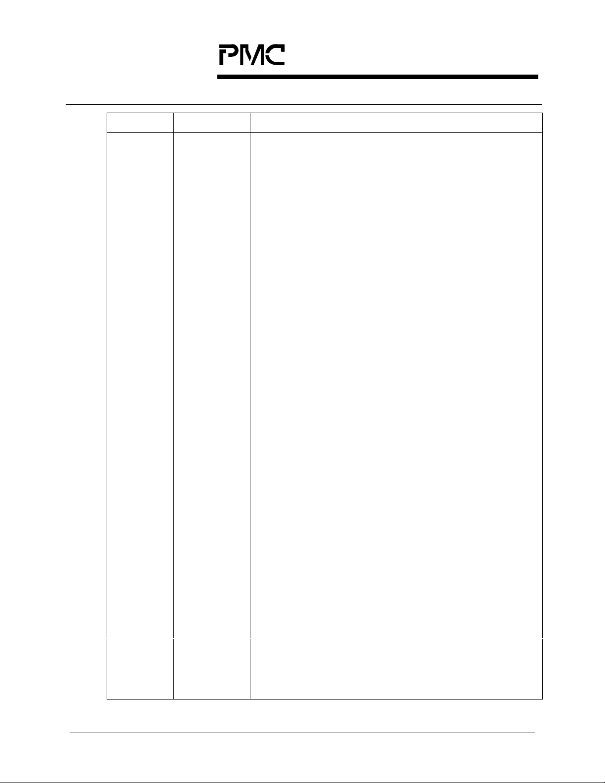
The SPECTRA-622 can be used in SONET/SDH network elements including
switches, terminal multiplexers, and add-drop multiplexers. In such applications,
the SPECTRA-622 line interface typically interfaces directly to electrical optical
modules. On the system side interface, the SPECTRA-622 connects directly to a
Telecombus. Figure 1 shows how the SPECTRA-622 is used to implement a 622
Mbit/s aggregate interface. In this application, the SPECTRA-622 performs
SONET/SDH section, line and path termination and the PM5362 TUPP-PLUS
performs tributary pointer processing and performance monitoring.
Figure 1 -STS-12 (STM-4/AU-3), STS-12 (STM-4/AU-4) or STS-12c (STM4-4c) Application with 19.44 MHz Byte Telecombus Interface
622 Mbit/s
Optical
Interface
Optical
Transceiver
RXD+/SD
TXD+/-
PM5313
SPECTRA-622
ACK
AD[31:0], ADP[4:1]
AC1J1V1[4:1]
APL[4:1]
DD[31:24], DDP[4]
DC1J1V1[4]
DPL[4]
DCK
DD[23:16], DDP[3]
DC1J1V1[3]
DPL[3]
DCK
DD[15:8], DDP[2]
DC1J1V1[2]
DPL[2]
DCK
DD[7:0], DDP[1]
DC1J1V1[1]
DPL[1]
DCK
ID[7:0], IDP
IC1J1
IPL
SCLK
ID[7:0], IDP
IC1J1
IPL
SCLK
ID[7:0], IDP
IC1J1
IPL
SCLK
ID[7:0], IDP
IC1J1
IPL
SCLK
PM5362
TUPP-PLUS
PM5362
TUPP-PLUS
PM5362
TUPP-PLUS
PM5362
TUPP-PLUS
OD[7:0], ODP
OTV5
OTPL
TPOH
OD[7:0], ODP
OTV5
OTPL
TPOH
OD[7:0], ODP
OTV5
OTPL
TPOH
OD[7:0], ODP
OTV5
OTPL
TPOH
Four
19.44 MHz
8-bit
IEEE P1396
Telecombus
Interfaces
Drop Add
PROPRIETARY AND CONFIDENTIAL 9
Page 42

PRODUCTION
DATASHEET
PMC-1981162 ISSUE 6 SONET/SDH PAYLOAD EXTRACTOR/ALIGNER FOR 622 MBIT/S
PMC-Sierra, Inc.
PM5313 SPECTRA-622
The system side interface of the SPECTRA-622 can also be configured to have a
77.76 MHz byte Te lecombus interface. Figure 2 shows how the SPECTRA-622 is
used to implement a 622 Mbit/s aggregate interface using the high-speed
Telecombus on the system side interface. In this application, the SPECTRA-622
performs SONET/SDH section , line and path termination.
Figure 2 -STS-12 (STM-4/AU-3), STS-12 (STM-4/AU-4) or STS-12c (STM4-4c) Application with 77.76 MHz Byte Telecombus Interface
622 Mbit/s
Optical
Interface
Optical
Transceiver
RXD+/SD
TXD+/-
PM5313
SPECTRA-622
AD[31:0], ADP[4:1]
ACK
AC1J1V1[4:1]
APL[4:1]
DD[31:0], DDP[4:1]
DC1J1V1[4:1]
DPL[4:1]
DCK
DFP
77.76 MHz
8-bit
High Speed
Telecombus
Interface
Drop Add
PROPRIETARY AND CONFIDENTIAL 10
Page 43

PRODUCTION
/s
PMC-Sierra, Inc.
PM5313 SPECTRA-622
DATASHEET
PMC-1981162 ISSUE 6 SONET/SDH PAYLOAD EXTRACTOR/ALIGNER FOR 622 MBIT/S
Four SPECTRA-622 devices can be connected to an OC-48 front end
transceiver device to implement a STS-48 (STM-16) aggregate interface. Figure
3 shows a block diagram for the STS-48 (STM-16) application. In this application,
the OC-48 transceiver performs SONET/SDH section and line processing and
the SPECTRA-622 devices perform SONET/SDH path processing, line rate
decoupling, and pointer processing.
Figure 3 -STS-48 (STM-16) Application
2488 Mbit
Optical
Interface
OC-48
Clock
Recovery
OC-48
Serial to
Parallel and
Parallel to
Serial
Conve rsion
POUT[7:0]
PIN[7:0]
OC-48 Front End
TOUT[7:0]
ROUT[7:0]
TOUT[7:0]
ROUT[7:0]
TOUT[7:0]
ROUT[7:0]
TOUT[7:0]
ROUT[7:0]
TFPO
TFPO
ROFP
TFPO
ROFP
TFPO
ROFP
ROFP
TFPI
TD[7:0]
PIN[7:0]
FPIN
TFPI
TD[7:0]
PIN[7:0]
FPIN
TFPI
TD[7:0]
PIN[7:0]
FPIN
TFPI
TD[7:0]
PIN[7:0]
FPIN
PM5342
SPECTRA-622
AD[31:0 ], ADP[ 4 :1]
DD[31:0], DDP[4:1]
PM5342
SPECTRA-622
AD[31:0], ADP[4:1]
DD[31:0], DDP[4:1]
PM5342
SPECTRA-622
AD[31:0 ], ADP[ 4 :1]
DD[31:0], DDP[4:1]
PM5342
SPECTRA-622
AD[31:0 ], ADP[ 4 :1]
DD[31:0], DDP[4:1]
AC1J1V1[4:1]
APL[4:1]
DC1J1V1[4:1]
DPL[4:1]
DCK, DFP
AC1J1V1[4:1]
APL[4:1]
DC1J1V1[4:1]
DPL[4:1]
DCK, DFP
AC1J1V1[4:1]
APL[4:1 ]
DC1J1V1[4:1]
DPL[4:1]
DCK, DFP
AC1J1V1[4:1]
APL[4:1]
DC1J1V1[4:1]
DPL[4:1]
DCK, DFP
ACK
IEEE P1396
ACK
ACK
ACK
Telecombus
Interfaces
Drop Add
PROPRIETARY AND CONFIDENTIAL 11
Page 44

PRODUCTION
DATASHEET
PMC-1981162 ISSUE 6 SONET/SDH PAYLOAD EXTRACTOR/ALIGNER FOR 622 MBIT/S
PMC-Sierra, Inc.
PM5313 SPECTRA-622
SPECTRA-622 can be used to implement OC-12 interfaces on channelised high
speed IP switches and routers. For OC-12 interfaces with DS-3 channelisation,
the SPECTRA-622 has on-chip DS-3 mappers to facilitate direct connection to
the PM7346 S/UNI-QJET for DS-3 framing. The circuit shown inFigure 4
implements a channelised OC-12 interface for the high speed router. The PCI
bus connects directly to the IP switch/router backplane.
Figure 4 -OC-12 Channelised DS-3 Interface for High Speed IP
Switches/Routers
Channelised OC-12 Card
622 Mbit/s
Optical
Interface
Opt
Opt
SPECTRA-
622
S/UNI-
QJET
S/UNI-
QJET
S/UNI-
QJET
FREEDM-8
FREEDM-8
FREEDM-8
FREEDM-8
FREEDM-8
FREEDM-8
Bus
Interface
PROPRIETARY AND CONFIDENTIAL 12
Page 45

PRODUCTION
PMC-Sierra, Inc.
PM5313 SPECTRA-622
DATASHEET
PMC-1981162 ISSUE 6 SONET/SDH PAYLOAD EXTRACTOR/ALIGNER FOR 622 MBIT/S
SPECTRA-622 allows simultaneous access to system-side DS-3 interface and
the system-side telecom bus interface. DS-3 access is selectable on an STS-1
basis. The SPECTRA-622 can be used to aggregate OC-12 traffic on a platform
that supports ATM, Frame Relay, IP, and TDM traffic. Figure 5 shows the
implementation of a multi-service channelised OC-12 interface using the
SPECTRA-622.
Figure 5 -Multi-service Channelised OC-12 Aggregate Interface for High
Speed IP Switches/Routers
PM5313
SPECTRA-622
PM7346
622 Mbit/s
Optical
Interface
Optical
Transceiver
RXD+/SD
TXD+/-
DS3TICLK[12:9]
DS3TDAT[12:9]
DS3ROCLK[12:9]
DS3RDAT[12:9]
TCLK[4:1]
TPOS[4:1]
RCLK[4:1]
RPOS[4:1]
S/UNI-QJET
ATM UTOPIA
LEVEL 2 BUS
(to ATM switch core)
DS3TICLK[8:7]
DS3TDAT[8:7]
DS3ROCLK[8:7]
DS3RDAT[8:7]
DD[15:8], DDP[2]
DC1J1V1[2]
DPL[2]
DCK
S/UNI-QJET
TCLK[4:1]
TPOS[4:1]
RCLK[4:1]
RPOS[4:1]
ID[7:0], IDP
IC1J1
IPL
SCLK
PM7346
PM5362
TUPP-PLUS
OD[7:0], ODP
OTV5
OTPL
TPOH
FREEDM-8
TCLK[1:0]
TD[1:0]
RCLK[1:0]
RD[1:0]
Drop Add
PM7366
19.44 MHz 8-bi t
IEEE P1396
Telecombus
Interface
(to channelised
router VT mapper)
PROPRIETARY AND CONFIDENTIAL 13
Page 46

PRODUCTION
PMC-Sierra, Inc.
PM5313 SPECTRA-622
DATASHEET
PMC-1981162 ISSUE 6 SONET/SDH PAYLOAD EXTRACTOR/ALIGNER FOR 622 MBIT/S
6 BLOCK DIAGRAM
P
K
C
L
U
K
C
H
L
S
T
O
C
W
,
T
H
O
,
T
O
W
,
T
W
O
,
K
T
L
P
A
C
F
D
P
P
P
C
C
C
R
R
R
T
T
T
/
/
/
I
S
S
I
I
D
A
R
A
L
L
L
R
T
T
K
S
O
L
K
T
L
L
C
,
T
,
C
D
D
L
D
D
L
S
L
L
S
T
T
T
T
F
T
,
K
I
L
E
C
R
T
H
M
O
K
G
T
L
N
P
P
T
,
E
C
F
,
K
H
H
H
H
L
O
O
O
O
C
T
T
T
T
T
T
T
T
T
N
P
E
F
H
H
H
O
O
O
P
P
P
T
T
T
TPOHCTRL
K
C
A
T
,
P
Y
K
F
D
L
A
R
C
T
H
,
H
O
D
O
P
A
P
T
T
T
TXD+/-
TDREF0, TDREF1
TDCK
TC1J1V1/TFPO
TD[7:0 ]
ATP[1:0]
PREFEN
PECL REF
PECLV
REFCLK+/-
RXD+/-
RRCLK+/-
C0, C1
PICLK
PIN[7:0]
Tx
Ring
Control Port
Clock
Tx Line
Synthesis
I/F
TPL
TDP
TFPI
SD
FPIN
OOF
Rx Line
I/F
Serial
Control Port
(CSPI)
TX
DLL
Clock and
Data
Recovery
(CRSI)
Rx Ring
Control Port
(RRCP)
]
]
0
0
:
:
1
3
[
[
I
O
P
P
C
C
S
S
Tx Transport
Overhead
Controller
(TTOC )
Tx Path O/H
Processor
(TPOP)
Path Trace Buffer
(SPTB)
Rx Path O / H
Processor
(RPOP)
RPOHCT RL
P
H
N
M
N
K
F
L
O
E
L
E
H
P
A
H
C
C
O
R
R
T
H
O
P
R
P
O
R
R
P
R
Transmit Path Processing
Slice (TPPS) #n, n= {1. .12 }
Receive Path Processing
Slice (RPPS) #n, n={1..12}
DPAIS
E
H
D
3
O
A
B
R
C
T
R
Tx
Section O/H
Processor
(TSOP)
Section
Trace
Buffer
(SSTB)
Section O/H
Processor
(RSOP)
P
T
K
F
L
A
P
C
D
C
P
P
R
C
C
R
R
R
/
R
R
S
/
/
I
O
S
I
D
L
R
A
L
L
Rx
Rx Transport
Overhead
Controller
(RTOC)
C
K
M
L
U
L
S
C
A
R
S
W
,
,
O
F
W
R
O
O
,
L
S
K
R
L
,
C
D
D
L
L
S
S
R
R
Processor
Receive APS,
Synchronization
Extractor and
Bit Error Monitor
Processor
H
H
K
L
O
O
C
T
R
,
R
H
O
W
R
O
,
L
K
R
L
,
C
D
D
L
L
R
R
Tx
Line O/H
(TLOP)
(RASE)
(BIDX)
Rx
Line O/H
(RLOP)
P
K
F
L
H
C
O
H
T
O
R
T
R
O
P
F
R
,
K
L
C
R
,
K
L
C
R
M
G
P
(TX_RE MUX)
(RX_DEMUX)
WAN
Synchronization
Controller
(WANS)
Tx Telecom
Align er
(TTAL)
DS3 Mapper
ADD Side
(D3MA)
Rx Telecom
DS3 Mapper
DROP Side
DPAIS
and
TPAIS
TPAIS
TPAISFP
DPAISFP
DPAISCK
Aligner
(RTAL)
(D3MD)
TPAISCK
ADD Bus
PRBS
Generator/
Monitor
(APGM )
DROP Bus
PRBS
Generator/
Monitor
(DPGM)
Microprocessor
I/F
]
]
E
B
E
B
0
0
/
:
:
L
S
W
B
3
7
A
C
[
1
R
D
/
[
D
R
B
A
R
W
B
T
S
R
Tx Pointer
Interpreter
B
B
T
E
N
B
I
M
(TPIP)
PMON
JTAG Test
Access Port
I
K
O
D
C
D
T
T
T
ADD_TSI
DROP_TSI
S
B
T
M
S
T
R
T
Add Bus
System
Inter face
Tx DS-3
System
Interface
Rx Tele combus
System
Interface
Rx DS-3
System
Inter f ace
DROP
DLL
ACK
AC1J1V1[4:1]/AFP[4:1]
APL[4:1]
AD[31:0]
ADP[4:1]
DS3TICLK[12:1]
DS3TDAT[12:1]
DCK
DC1J1V1[4:1]
DPL[4:1]
DD[31:0]
DDP[4:1]
DFP
DS3RICLK
DS3ROCLK[12:1]
DS3RDAT[12:1]
DMODE[1:0]
PROPRIETARY AND CONFIDENTIAL 14
Page 47

PRODUCTION
PMC-Sierra, Inc.
PM5313 SPECTRA-622
DATASHEET
PMC-1981162 ISSUE 6 SONET/SDH PAYLOAD EXTRACTOR/ALIGNER FOR 622 MBIT/S
7 LOOPBACK MODES
P
K
C
L
U
K
C
H
S
L
T
O
C
W
,
T
H
O
,
T
W
O
,
T
W
O
K
T
L
P
A
C
F
D
P
P
P
C
C
C
R
R
R
T
T
T
/
/
/
I
S
S
I
I
D
A
R
A
L
L
L
R
T
T
,
K
S
O
L
K
T
L
L
C
,
T
,
C
D
D
L
L
D
D
S
S
L
L
T
T
T
T
F
T
,
K
I
L
E
C
R
T
H
M
O
K
T
G
L
N
P
T
P
E
,
,
F
C
H
H
H
H
K
L
O
O
O
O
C
T
T
T
T
T
T
T
T
T
K
N
P
L
F
E
C
H
H
H
H
O
O
O
O
P
P
P
P
T
T
T
T
TPOHCTRL
K
C
A
T
,
P
Y
F
D
A
R
T
H
,
O
D
P
A
T
T
TDREF0, TDREF1
TC1J1V1/TFPO
Line Loopback
(LLE=1)
REFCLK+/-
TXD+/-
TDCK
TD[7:0]
ATP[1:0]
PREFE N
PECLREF
PECLV
RXD+/ -
RRCLK+/-
C0, C1
PICLK
PIN[7:0]
Rx Ring
(RRCP)
P
F
P
C
R
R
/
S
O
L
T
A
D
P
C
R
R
/
S
I
A
L
K
L
C
P
C
R
R
/
I
D
R
L
Tx
Section O/H
Processor
(TSOP)
Section
Trace
Buffer
(SSTB)
Rx
Section O/H
Processor
(RSOP)
Tx Transport
Overhead
Controller
(TTOC)
Rx Transport
Overhead
Controller
(RTOC)
C
K
M
L
U
L
S
C
A
R
S
W
,
,
O
F
W
R
O
O
,
L
S
K
R
L
,
C
D
D
L
L
S
S
R
R
Line O/H
Processor
(TLOP)
Receive APS,
Synchronizati on
Extractor and
Bit Error Monitor
(RASE)
(BIDX)
Line O/H
Processor
(RLOP)
P
H
H
K
F
L
O
O
H
C
R
T
,
O
H
R
T
O
W
R
R
O
,
L
K
R
L
,
C
D
D
L
L
R
R
JTAG Test
Access Port
I
O
K
D
D
C
T
T
T
ADD_TSI
DROP_TSI
S
B
T
M
S
T
R
T
Add Bus
System
Interf a ce
Tx DS-3
System
Inte rf ace
Rx Telecombus
System
Interf a c e
Rx DS- 3
System
Inter face
DROP
DLL
ACK
AC1J1V1[4:1]/AFP[4:1]
APL[4:1]
AD[31:0]
ADP[4:1]
DS3TICLK[12:1]
DS3TDAT[12:1]
DCK
DC1J1V1[4:1]
DPL[4:1]
DD[31:0]
DDP[4:1 ]
DFP
DS3RICLK
DS3ROCLK[12:1]
DS3RDAT[12:1]
DMODE[1:0]
ADD Bus
Al igne r
(TTAL)
ADD Side
(D3MA)
DS3 Line Loop-
back
(DS3LLBEN=1)
Rx Telecom
Aligner
(RTAL)
DS3 Mapper
DROP Side
(D3MD)
TPAISCK
TPAIS
TPAISFP
DPAISCK
PRBS
Generator/
Monitor
(APGM)
DROP Bus
PRBS
Generator/
Monitor
(DPGM)
Microprocess or
I/F
]
]
B
E
E
B
0
0
/
:
:
L
S
W
B
3
7
A
C
[
1
R
D
/
[
D
R
B
A
R
W
B
B
T
T
N
S
I
R
Tx Pointer
Interp rete r
(TPIP)
Line Loopback
PMON
B
E
B
M
System Side
(SLLB E N = 1)
Tx Telecom
Tx Path O/H
Processor
(TPOP)
Path Trace Buffer
(SPTB)
Rx Path O/H
Processor
(RPOP)
RPOHCTRL
P
H
N
N
M
K
F
E
L
O
E
L
H
P
A
H
C
C
O
R
R
T
O
H
P
R
P
O
R
R
P
R
DS3 Mapper
Transmit Path Processing
Slice (TPPS) #n, n={1..12}
Receive Path Processing
Slice (RPPS) #n, n={1..12}
DPAIS
and
TPAIS
DPAIS
DPAISFP
E
H
D
3
O
A
B
R
C
T
R
(TX_REMUX)
Tx
(RX_DEM UX)
Rx
WAN
Synchronizat ion
Controller
(WANS)
O
P
F
R
K
,
L
K
C
L
H
C
O
R
T
,
R
K
L
C
R
M
G
P
Tx
Ring
Control Port
Clock
Tx Line
Synthesis
I/F
TPL
TDP
TFPI
SD
FPIN
OOF
Rx Line
I/F
Serial
Control Port
]
]
0
0
:
:
3
1
[
[
I
O
P
P
C
C
S
S
(CSPI)
TX
DLL
Serial Diagnostic
loopback (SDLE=1)
or
Parallel Diagnostic
Loopback (PDLE=1)
Clock and
Data
Recovery
(CRSI)
Control Port
PROPRIETARY AND CONFIDENTIAL 15
Page 48

PRODUCTION
DATASHEET
PMC-1981162 ISSUE 6 SONET/SDH PAYLOAD EXTRACTOR/ALIGNER FOR 622 MBIT/S
PMC-Sierra, Inc.
PM5313 SPECTRA-622
8 DESCRIPTION
The PM5313 SONET/SDH PAYLOAD EXTRACTOR/ALIGNER (SPECTRA-622)
terminates the transport and path overhead of STS-12 (STM-4/AU3 or STM4/AU4) and STS-12c (STM-4-4c) streams at 622.08 Mbit/s. The SPECTRA-622
implements significant function s for a SONET/SDH compliant line interface, as
well as DS3 mapping.
The SPECTRA-622 receives SONET/SDH frames via a bit serial interface,
recovers clock and data, and terminates the SONET/SDH section (regenerator
section), line (multiplexer section), and path. It performs framing (A1, A2),
descrambling, detects alarm conditions, and monitors section and line bit
interleaved parity (BIP) (B 1, B2), accumulating error co unts at each level for
performance monitori ng purp oses. B2 er r ors are also moni t or ed to det ect sig nal
fail and signal degrade threshold crossing alarms. Line remote error indications
(M1) are also accumulated. A 16 or 64 byte section trace (J0) message may be
buffered and compared against an expected message. In addition, the
SPECTRA-622 interprets the received payload pointers (H1, H2), detects path
alarm conditions, detects and accumulates path BIPs (B3), monitors and
accumulates path Remote Error Indications (REIs), accumulates and compares
the 16 or 64 byte path trace (J1) message against an expected result and
extracts the synchronous payload envelope (virtual container). All transport and
path overhead bytes are extracted and serialized on lower rate interfaces,
allowing additional external processing of overhead, if desired.
The extracted SPE (VC) is placed on a Telecom DROP bus and optionally
serialized into DS3 streams. For Telecombus applications, frequency offsets
(e.g., due to plesiochronous network boundaries, or the loss of a primary
reference timing source) and phase differences (due to normal network
operation) between the received data stream and the DROP bus are
accommodated by pointer adjustments in the DROP bus. For the DS3
application, the SPECTRA-622 demaps the DS3s from the STS-12
(STM-4/AU3/AU4) SPE and provides serialized bit streams with derived clocks.
Both the Telecom and DS3 DROP buses can be active at the same time
supporting a mixed use de-multiplexer function on the system DROP side.
The SPECTRA-622 transmits SONET/SDH frames, via a bit serial interface, and
formats section (regenerator section), line (multiplexer section), and path
overhead appropriately. The SPECTRA-622 provides transmit path origination for
a SONET/SDH STS -12 (STM-4/AU3 or STM-4/AU4) or STS-1 2c (STM-4-4c)
stream. It performs framing pattern insertion (A1, A2), scrambling, alarm signal
insertion, and creates section and line BIPs (B1, B2) as required to allow
performance monitoring at the far end. Line remote error indications (M1) are
PROPRIETARY AND CONFIDENTIAL 16
Page 49

PRODUCTION
DATASHEET
PMC-1981162 ISSUE 6 SONET/SDH PAYLOAD EXTRACTOR/ALIGNER FOR 622 MBIT/S
PMC-Sierra, Inc.
PM5313 SPECTRA-622
optionally inserted. A 16 or 64 byte section trace (J0) message may be inserted.
In addition, the SPECTRA-622 generates the transmit payload pointers (H1, H2),
creates and inserts the path BIP, optionally inserts a 16 or 64 byte path trace (J1)
message, optionally inserts the path status byte (G1). In addition to its basic
processing of the transmit SONET/SDH overhead, the SPECTRA-622 provides
convenient access to all overhead bytes, which are inserted serially on lower rate
interfaces, allowing additional external sourcing of overhead, if desired. The
SPECTRA-622 also supports the insertion of a large variety of errors into the
transmit stream, such as framing pattern errors and BIP errors, which are useful
for system diagnostics and tester applications.
The inserted SPE (VC) is either sourced from a Telecombus ADD stream or from
DS3 serial streams. For Telecombus applications, the SPECTRA-622 maps the
SPE from a Telecom ADD bus into the transmit stream. Frequency offsets (e.g.,
due to plesiochronous network boundaries, or the loss of a primary reference
timing source) and phase differences (due to normal network operation) between
the transmit data stream and the ADD bus are accommodated by pointer
adjustments in the transmit stream. For the DS3 application, the SPECTRA-622
maps the DS3s into an STS-12 (STM-4/AU3/AU4) SPE. Both the Telecom and
DS3 ADD buses can be active at the same time supporting a mixed use
multiplexer function on the system ADD side.
The SPECTRA-622 supports Time-Slot Interchange (TSI) on the Telecom ADD
and DROP buses. On the DROP side, the TSI views the receive stream as
twelve independent time-division multiplexed columns of data (i.e. twelve
constituent STS-1 (STM-0/AU3) or equivalent streams or time-slots or columns).
Any column can be connected to any time-slot on the DROP bus. Both column
swapping and broadcast are supported. Time-Slot Interchange is independent of
the underlying payload mapping formats. Similarly, on the ADD side, data from
the ADD bus is treated as twelve independent time-division multiplexed columns.
Assignment of data columns to transmit time-slots (STS-1 (STM-0/AU3) or
equivalent streams) is arbitrary.
The transmitter and receiver are independently configurable to allow for
asymmetric interfaces. Ring control ports are provide to pass control and status
information between mate transceivers. The SPECTRA-622 is configured,
controlled and monitored via a generic 8-bit microprocessor bus interface.
The SPECTRA-622 is implemented in low power, +3.3 Volt, CMOS technology. It
has TTL and pseudo ECL (PECL) compatible inputs and outputs and is packaged
in a 520 pin SBGA package.
PROPRIETARY AND CONFIDENTIAL 17
Page 50

PRODUCTION
DATASHEET
PMC-1981162 ISSUE 6 SONET/SDH PAYLOAD EXTRACTOR/ALIGNER FOR 622 MBIT/S
PMC-Sierra, Inc.
PM5313 SPECTRA-622
9 PIN DIAGRAMS
The SPECTRA-622 is available in a 520 pin SBGA package having a body size of 40
mm by 40 mm and a ball pitch of 1.27 mm.
Section views of the SPECTRA-622 Pin diagram follow Figure 6
Figure 6 -Full View of SPECTRA-622 diagram
A31-T31 A1-T17
AL18-U31 UL-AL17
Bottom View
PROPRIETARY AND CONFIDENTIAL 18
Page 51

PRODUCTION
PMC-Sierra, Inc.
PM5313 SPECTRA-622
DATASHEET
PMC-1981162 ISSUE 6 SONET/SDH PAYLOAD EXTRACTOR/ALIGNER FOR 622 MBIT/S
Figure 7 -Section View of SPECTRA-622 Pin diagram, A1-T17
17 16 15 14 13 12 11 10 9 8 7 6 5 4 3 2 1
RSVD2 GND RSVD1 B3E DPAIS DPAISP GND D[1] A[11] A[6] A[1] GND
PGMTC
TLRDI/T
TLAIS/T
RCPDAT
RLAIS/R VDD
LK
RCPFP
GND RPOH
VDD
VDD
RPOHE
RPOHFPTPOHENTPAISF
TPOHRDYTPOHCLKDPAISC
TPOH TPAIS D[7] D[3] INTB A[9] A[4] CSB
N
RPOH
TPOHFP
LK
P
TPAISC
K
D[4] D[0] A[10] A[5] A[0] RDB/E TDI TCK GND VDD GND
K
WRB/R
D[6] D[2] A[13] A[8] A[3] ALE RSTB TMS VDD VDD
D[5] VDD A[12] A[7] A[2] MBEB
VBIAS
Bottom View
TRS
GND GND GND VDD
TB
TDO VDD VDD GND GND
WB
SCPO
VDD
[1]
SCP
I
[1]
N/C N/C PREFEN PECLV
N/C
N/C ANA
ANA
LOG
AVS
[10]
AVD
[12]
QAVD
VDD
PBI
AS
AVD[14] AVD[13]
[2]
AVS
AVS[14] SAVS[1]
[13]
TDR
EF1
AVS
PBIAS
[18]
VDD VDD VDD GND GND
SCPI
[1]
N/C N/C N/C GND
LOG
AVD
[9]
AVS
[11]
[0]
AVS
[17]
[0]
[0]
N/C ANA
LOG
AVS
[8]
AVD
[11]
ATP0 ATP1 GND
AVD
[18]
SAVS[2]
SCPO
SCPI
SAVS[0] QAVS[0]
REFCLK+REFCLK
TXD+ TXD-
PECLRE
[0]
[2]
AVD
[10]
AVD
[8]
AVD
[17]
F
GND
SCPI
[3]
N/C ANA
LOG
AVS
[9]
AVS
[12]
-
TDREF0
SAVS[3]
A
B
C
D
E
F
G
H
J
K
L
M
N
P
R
T
PROPRIETARY AND CONFIDENTIAL 19
Page 52

PRODUCTION
PMC-Sierra, Inc.
PM5313 SPECTRA-622
DATASHEET
PMC-1981162 ISSUE 6 SONET/SDH PAYLOAD EXTRACTOR/ALIGNER FOR 622 MBIT/S
Figure 8 -Section View of SPECTRA-622 Pin diagram, U1-AL17
DS3RO
CLK[8]
DS3RO
CLK[7]
DS3RO
CLK[6]
DS3RO
CLK[5]
N/C GND
DS3TD
VDD
AT[4]
DS3TD
VDD
AT[3]
VDD N/C
DS3TD
GND
AT
[2]
DS3TD
AT[1]
DS3TIC
LK[3]
N/C N/C
DS3TIC
LK
[4]
N/C
N/C N/C
Bottom View
DS3RD
N/C
DS3TIC
LK
[2]
DS3TIC
LK
[1]
DS3RO
CLK[4]
DS3RD
DS3RD
DS3RD
VDD TFPI N/C N/C N/C N/C VDD N/C N/C N/C N/C
AT[4]
DS3RO
CLK[3]TD[6]TD[2]
DS3RO
AT[3]
CLK[2]TD[7]
DS3RO
AT[2]
CLK[1]
GND TDCK
AT[1]
OOF FPIN
TC1J1V
TD[3]
1/TFO
TDP TD[4] TD[0] TPL
TD
[5]
PIN
[7]
TD[1] TCLK GND
AVD
AVS[4]
[4]
QAVS[1]QAVD
AVS[16]
AVD
PBIAS
[15]
PBIAS
SAVS
VDD
AVD
[3]
AVD
[6]
N/C
ANA
LOG
N/C N/C
N/C N/C N/C N/C GND
PIN
[3]
PIN
[2]
PIN
PICLK GND VDD GND
[1]
PIN
[0]
PIN
[6]
PIN
[5]
PIN
[4]
SAVS[5]
N/C
ANA
LOG
[1]
AVD
[3]
[16]
AVS
[1]
[15]
AVS
[6]
[0]
AVD
SAVS
[2]
[7]
AVD
AVS
[5]
[5]
N/C
AVD
ANA
LOG
VDD VDD N/C GND
VDD VDD GND GND
GND GND GND VDD
[7]
N/C
ANA
LOG
SD SAVS[4]
C0 C1
RRCLK
RRCLK-
RXD+ RXD-
AVD
GND
[0]
AVS[1]AVD
AVS
AVS
[3]
AVS
AVS
[7]
N/C
ANA
ANA
LOG
LOG
N/C
U
V
W
+
Y
AA
AB
[1]
AC
[2]
AD
[6]
AE
AF
AG
AH
AJ
AK
AL
17 16 15 14 13 12 11 10 9 8 7 6 5 4 3 2 1
PROPRIETARY AND CONFIDENTIAL 20
Page 53

PRODUCTION
PMC-Sierra, Inc.
PM5313 SPECTRA-622
DATASHEET
PMC-1981162 ISSUE 6 SONET/SDH PAYLOAD EXTRACTOR/ALIGNER FOR 622 MBIT/S
Figure 9 -Section View of SPECTRA-622 Pin diagram, AL18-U31
U
V
W
Y
AA
AB
AC
AD
AE
AF
AG
AH
AJ
AK
AL
AC1J1V1
APL[3]
AD[19] AD[20] AD[21] AD[22] AD[23]
ADP[3] N/C DPL[3]
DD[17] DD[18] DD[19] DD[20] DD[21]
GND DD[22] DD[23] DDP[3] VDD
APL[4]
AD[27] AD[28] AD[29] AD[30] N/C
AD[31] ADP[4] N/C DPL[4]
DD[24] DD[25] DD[26] DD[27] DD[28]
GND DD[29] DD[30] DDP[4] N/C
DD[31] N/C DFP N/C VDD
GND DCK VDD VDD
GND GND VDD VDD
GND VDD GND
VDD GND GND GND
/AFP
[3]
AC1J1V1
/AFP
[4]
AD[16] AD[17] AD[18]
DC1J1V1
AD[24] AD[25] AD[26]
[3]
VBIAS
[0]
DD[16]
DC1J1V1
[4]
DMODE
[1]
DS3TDA
T[12]
DS3TDA
T[11]
DS3RICL
K
DMODE
[0]
DS3TDA
T[10]
DS3TDA
T[9]
N/C
GND
N/C N/C N/C
N/C N/C
DS3TICL
N/C
DS3TICL
K[12]
DS3TICL
K[11]
K[10]
DS3TICL
K[9]
N/C
Bottom View
DS3RDA
T[11]
DS3RDA
T[10]
DS3RDA
T[9]
DS3ROC
LK[12]
DS3RDA
T[12]
N/C
DS3ROC
LK[11]
DS3ROC
LK[10]
DS3ROC
LK[9]
VDD N/C N/C
DS3TDA
T[8]
DS3TDA
T[7]
DS3TDA
T[6]
GND
DS3TDA
T[5]
N/C N/C
N/C
DS3TICL
K[8]
DS3TICL
K[7]
DS3TICL
K[6]
DS3TICL
K[5]
DS3RDA
T[5]
DS3RDA
T[6]
DS3RDA
T[7]
DS3RDA
T[8]
N/C
31 30 29 28 27 26 25 24 23 22 21 20 19 18
PROPRIETARY AND CONFIDENTIAL 21
Page 54

PRODUCTION
PMC-Sierra, Inc.
PM5313 SPECTRA-622
DATASHEET
PMC-1981162 ISSUE 6 SONET/SDH PAYLOAD EXTRACTOR/ALIGNER FOR 622 MBIT/S
Figure 10 -Section View of SPECTRA-622 Pin diagram, A31-T31
31 30 29 28 27 26 25 24 23 22 21 20 19 18
A
VDD GND GND GND N/C GND TOHCLK
B
GND VDD GND N/C TACK RAD TTOHFP TSUC TSLDCLK RCLK
C
GND GND VDD VDD N/C TAFP TTOHEN TLOW TLD RFPO RTOH RSUC RSLDCLK
D
GND N/C VDD VDD N/C
E
ACK APL[1]
F
GND AD[1] AD[2] AD[3] AD[4]
G
AD[5] AD[6] AD[7] ADP[1] N/C
AC1J1V1/
AFP[1]
AD[0] VDD TFP TAD TTOH TSOW TSLD VDD ROH RLDCLK SALM
PGMRCLKTTOHCL
TOWCL
K
TOH TLDCLK N/C
K
TTOHREI
RTOHCL
K
GND
ROHCL
K
RTOHF
P
ROWCL
RSOW RSLD
RLOW RLD LOF
RALM
K
LRDI/RRCP
LOS/RRCPF
LAIS/RRCP
CLK
P
DAT
H
J
K
L
M
N
P
R
T
DC1J1V1
DPL[1]
DD[3] DD[4] DD[5] DD[6] DD[7]
DDP[1] APL[2]
GND AD[10] AD[11] AD[12] VDD
AD[13] AD[14] AD[15] ADP[2] N/C
DC1J1V1
DPL[2]
DD[11] DD[12] DD[13] DD[14] DD[15]
N/C N/C N/C DDP[2] N/C
GND GND VDD VDD VDD
DD[0] DD[1] DD[2]
[1]
AC1J1V1/
AFP[2]
DD[8] DD[9] DD[10]
[2]
AD[8] AD[9]
Bottom View
PROPRIETARY AND CONFIDENTIAL 22
Page 55

PRODUCTION
DATASHEET
PMC-1981162 ISSUE 6 SONET/SDH PAYLOAD EXTRACTOR/ALIGNER FOR 622 MBIT/S
PMC-Sierra, Inc.
PM5313 SPECTRA-622
10 PIN DESCRIPTION (520)
10.1 Serial Line side Interface Signals
Pin Name Type Pin
Function
No.
PECLV Input G2 The PECL signal voltage select (PECLV) selects
between 3.3V PECL or 5V PECL signaling for the
PECL inputs. When PECLV is low, the PECL inputs
expect a 5V PECL signal. When PECLV is high, the
PECL inputs expect a 3.3V PECL signal. The PECL
biasing pins PBIAS[3:0] should be set to the
appropriate voltage.
This input pin is 5 Volt tolerant.
Please refer to the Operation section for a
discussion of PECL interfacing issues
REFCLK+
REFCLK-
PECL
Input
M2M1The differential reference clock inputs (REFCLK+/-)
must provide a jitter-free 77.76 MHz reference
clock. It is used as the reference clock by both
clock recovery and clock synthesis circuits.
When the WAN Synchronization controller is used,
REFCLK+/- is supplied using a VCXO. In that
application, the transmi t dir ecti on can be externally
looped timed to the line receiver in order to meet
wander transfer and holdover requirements.
Please refer to the Operation section for a
discussion of PECL interfacing issues.
PROPRIETARY AND CONFIDENTIAL 23
Page 56

PRODUCTION
DATASHEET
PMC-1981162 ISSUE 6 SONET/SDH PAYLOAD EXTRACTOR/ALIGNER FOR 622 MBIT/S
PMC-Sierra, Inc.
PM5313 SPECTRA-622
Pin Name Type Pin
No.
RXD+
RXD-
RRCLK+
RRCLK-
PECL
Input
PECL
Input
Y2Y1The receive differential data PECL inputs (RXD+/-)
W1W2The receive differential clock inputs (RRCLK+/-) are
Function
contain the STS-12 (STM-4) 622.08 Mbit/s NRZ
encoded bit serial receive stream. The receive
clock is recovered from the RXD+/- bit stream when
clock recovery is not bypassed. RXD+/- is sampled
on the rising edge of RRCLK+/- (falling edge may
be used by reversing RRCLK+/-) when clock
recovery is bypassed. The polarity of the RXD pins
can be changed by the RXDINV bit in register
0003H.
Clock recovery bypass is selectable using the
RBYP bit in the SPECTRA-622 Line Configuration
#1 register.
Please refer to the Operation section for a
discussion of PECL interfacing issues.
used when clock recovery is bypassed. RRCLK+/-
is nominally a 622.08 MHz 50% duty cycle clock
and provides timing for the SPECTRA-622 receive
functions. In this case, RXD+/- is sampled on the
rising edge of RRCLK+/-. RRCLK+/- is ignored
when clock recovery is enabled.
Clock recovery bypass is selectable using the
RBYP bit in the SPECTRA-622 Line Configuration
#1 register.
Please refer to the Operation section for a
discussion of PECL interfacing issues.
PROPRIETARY AND CONFIDENTIAL 24
Page 57

PRODUCTION
DATASHEET
PMC-1981162 ISSUE 6 SONET/SDH PAYLOAD EXTRACTOR/ALIGNER FOR 622 MBIT/S
PMC-Sierra, Inc.
PM5313 SPECTRA-622
Pin Name Type Pin
No.
SD PECL
U2
Input
TXD+
TXD-
PECL
Output
P2P1The transmit differe nti al data outputs (TXD+/-)
Function
The receive signal detect PECL input (SD)
indicates the presence of valid receive signal power
from the Optical Physical Medium Dependent
Device. A PECL logic high indicates the presence of
valid data. A PECL logic low indicates a loss of
signal.
In clock recovery mode, when SD is low, the
receive serial data is forced to all zeros and the
phase locked loop switches to the reference clock
(REFCLK+/-) to keep the recovered clock in range.
These inputs must be DC coupled. Please refer to
the Operation section for a discussion of PECL
interfacing issues.
contain the STS-12 (STM-4) 622.08 Mbit/s NRZ
encode bit serial transmit stream. The TXD+/-
outputs are driven using the synthesized clock from
the CSU or the recovery clock from the CRU when
loop timing is enabled. Loop timing is enabled by
setting the LOOPT bit in the SPECTRA-622 Line
Configuration #1 register to logic one. The
TC1J1V1/TFPO output may be used to identify the
frame alignment on TXD+/-. It will rising 15 bits (+/-
3 bits) before the first byte of the SPE.
Please refer to the Operation section for a
discussion of PECL interfacing issues.
SCPO[1]
SCPO[0]
Tristate
Output
E4D2The status and control port outputs (SCPO[1:0])
provides two drive points for controlling auxiliary
devices. The signal levels on these outputs
correspond to the bit values contained in the
SPECTRA-622 Serial Control Port Status and
Control register.
SCPO[1:0] can be tristate using the SCPO_TS bit
in the SPECTRA-622 Serial Control Port Status and
Control register. On reset, these outputs will be
tristate by default.
PROPRIETARY AND CONFIDENTIAL 25
Page 58

PRODUCTION
DATASHEET
PMC-1981162 ISSUE 6 SONET/SDH PAYLOAD EXTRACTOR/ALIGNER FOR 622 MBIT/S
PMC-Sierra, Inc.
PM5313 SPECTRA-622
Pin Name Type Pin
Function
No.
SCPI[3]
SCPI[2]
SCPI[1]
SCPI[0]
Input E1
E2
F5
E3
The status and control port inputs (SCPI[3:0]) are
used to monitor the operation of auxiliary devices.
An interrupt may be generated when state changes
are detected on these monitored signals. State
changes and the real-time signal levels on this port
are available in the SPECTRA-622 Serial Control
Port Status and Control register. Each of the inputs
contains an internal pull up resistor.
10.2 Parallel Line Side Interface Signals
Pin Name Type Pin
Function
No.
PICLK Input AK4 The parallel input clock (PICLK) provides timing for
SPECTRA-622 receive function when the device is
configured for the parallel interf ace mode of
operation. PICLK is a 77.76 MHz nominally 50%
duty cycle clock.
PIN[7:0] and FPIN are sampled on the rising-edge
of PICLK.
PIN[0]
PIN[1]
PIN[2]
PIN[3]
PIN[4]
PIN[5]
PIN[6]
PIN[7]
Input
AL5
AK5
AJ5
AH5
AK6
AJ6
AH6
AJ7
The parallel data input (PIN[7:0]) bus carries the
byte-serial STS-12 (STM-4) stream when the
device is configured for the parallel interface mode
of operation. PIN[7] is the most significant bit
(corresponding to bit 1 of each serial word, the first
bit received). PIN[0] is the least significant bit
(corresponding to bit 8 of each serial word, the last
bit received).
The polarity of the PIN[7:0] pins can be changed by
the RXDINV bit in register 0003H.
PIN[7:0] is sampled on the rising edge of PICLK.
PROPRIETARY AND CONFIDENTIAL 26
Page 59

PRODUCTION
DATASHEET
PMC-1981162 ISSUE 6 SONET/SDH PAYLOAD EXTRACTOR/ALIGNER FOR 622 MBIT/S
PMC-Sierra, Inc.
PM5313 SPECTRA-622
Pin Name Type Pin
Function
No.
FPIN Input AH7 The active-high framing position input (FPIN) signal
indicates the SONET/SDH frame position on the
PIN[7:0] bus when the device is configured for the
parallel interface mode of operation. The operation
of the FPIN input is controlled by the PFPEN bit in
the CRSI Configuration and Interrupt register.
When PFPEN is set to logic one, FPIN is set high to
mark the first synchronous payload envelope byte
position after the J0/Z0 bytes on PIN[7:0].
FPIN may also mark the third A2 byte as controlled
by FPPOS in SPECTRA-622 Line Configuration #2
register (0003H)
When PFPEN is set to logic zero, FPIN is ignored
and the SPECTRA-622 will frame to the incoming
data on PIN[7:0]. The SPECTRA-622 will frame to
the incoming data on PIN[7:0] regardless of the
byte alignment or frame alignment of the incoming
stream.
FPIN is sampled on the rising edge of PICLK.
OOF Output AH8 The out of frame (OOF) signal is high while the
SPECTRA-622 is out of frame. OOF is set low
while the SPECTRA-622 is in-frame. An out of
frame declaration occurs when four consecutive
errored framing patterns (A1 and A2 bytes) have
been received. OOF can be used to enable an
upstream framing pattern detector to search for the
framing pattern.
OOF is updated on the rising edge of RCLK.
PROPRIETARY AND CONFIDENTIAL 27
Page 60

PRODUCTION
DATASHEET
PMC-1981162 ISSUE 6 SONET/SDH PAYLOAD EXTRACTOR/ALIGNER FOR 622 MBIT/S
PMC-Sierra, Inc.
PM5313 SPECTRA-622
Pin Name Type Pin
Function
No.
TDCK Input AL10 The parallel transmit data clock (TDCK) provides
timing for SPECTRA-622 transmit function
operation when the device is configured for the
parallel interface mode of operation only. When
both the serial and parallel interfaces are enabled,
the parallel input clock is ignored.
TDCK is a 77.76 MHz nominally 50% duty cycle
clock.
TFPI Input AG10 The transmit frame pulse input is an active high
pulse identifying the first synchronous payload
envelope byte in the STS-12 (STM-4) frame on
TD[7:0] bus or TXD+/- outputs. Selection of whether
TFPI indicates framing position on the TD[ 7:0] or
the TXD+/- is controlled by the TX_LIFSEL[1:0] bits
in the SPECTRA-622 Line Configuration #1
register. If LIFSEL is 01b, TFPI indicates framing
position on the TD[7:0] bus. If TX_LIFSEL[1:0] is
00b or 11b, TFPI indicates framing position on the
TXD+/- outputs.
TD[0]
TD[1]
TD[2]
TD[3]
TD[4]
TD[5]
TD[6]
TD[7]
Output AK8
AL8
AH9
AJ9
AK9
AL9
AH10
AJ10
TFPI should be set high for a single TCLK period
every 9720 TCLK cycles. It is not necessary for
TFPI to be present at every frame, an internal
counter fly-wheels based on the mos t recent TFPI
received. TFPI may be set low if such
synchronization is not required.
TFPI is sampled on the rising edge of TCLK.
The parallel transmit data (TD[7:0]) bus carries the
STS-12 (STM-4) SONET/SDH transmit stream in
byte serial format. TD[7] is the most significant bit
(corresponding to bit 1 of each serial word, the first
bit transmitted). TD[0] is the least significant bit
(corresponding to bit 8 of each serial word, the last
bit transmitted).
TD[7:0] is updated on the rising edge of TCLK.
PROPRIETARY AND CONFIDENTIAL 28
Page 61

PRODUCTION
DATASHEET
PMC-1981162 ISSUE 6 SONET/SDH PAYLOAD EXTRACTOR/ALIGNER FOR 622 MBIT/S
PMC-Sierra, Inc.
PM5313 SPECTRA-622
Pin Name Type Pin
Function
No.
TPL Output AK7 The transmit payload output (TPL) is an active high
signal that indicates when the transmit data bus
TD[7:0] is carrying a payload byte. It is set high
during path overhead and payload bytes and low
during transport overhead bytes. TPL is set high
during the H3 byte to indicate a negative pointer
justification event and set low during the byte
following H3 to indicate a positive pointer
justification event.
TPL is updated on the rising edge of TCLK.
TC1J1V1/ Output AJ8 The transmit composite timing signal (TC1J1V1)
indicates the frame, payload and tributary
multiframe boundaries on the transmit data bus
TD[7:0] when the TC1J1V1EN bit in the SPECTRA622 Transmit Telecom Bus Configuration register is
set high. TC1J1V1 pulses high with the transmit
payload active signal (TPL) set low to mark the first
STS-1 (STM-0/AU3) identification byte (C1).
TC1J1V1 pulses high with TPL set high to mark the
path trace byte(s) (J1). Optionally, the TC1J1V1
signal pulses high on the V1 byte(s) to indicate
tributary multiframe boundaries.
TC1J1V1 is updated on the rising edge of TCLK.
TFPO Output The transmit frame pulse output (TFPO) is an
active-high signal marking the frame alignment on
the serial stream TXD+/- or parallel transmit data
TD[7:0] when the TC1J1V1EN bit in the SPECTRA622 Transmit Telecom Bus Configuration register is
set low. In parallel mode, TFPO is set high for a
single TCLK period during the first SPE
(synchronous payload envelope) byte after the
J0/Z0 bytes on TD[7:0]. In serial mode, it will rising
15 bits (+/- 3 bits) before the first byte of the SPE
on TXD.
TFPO is updated on the rising edge of TCLK.
PROPRIETARY AND CONFIDENTIAL 29
Page 62

PRODUCTION
DATASHEET
PMC-1981162 ISSUE 6 SONET/SDH PAYLOAD EXTRACTOR/ALIGNER FOR 622 MBIT/S
PMC-Sierra, Inc.
PM5313 SPECTRA-622
Pin Name Type Pin
Function
No.
TDP Output AK10 T he transmit data parity signal (TDP) indicates the
parity of the transmit line interface signals. The
transmit data bus (TD[7:0]) is always included in
parity calculations. The INCTPL and INCTC1J1V1
register bits in the SPECTRA-622 Transmit
Telecom Bus Configuration register control the
inclusion of the TPL and TC1J1V1 signals in parity
calculation and the sense (odd/even) of the parity.
TDP is updated on the rising edge of TCLK.
PROPRIETARY AND CONFIDENTIAL 30
Page 63

PRODUCTION
DATASHEET
PMC-1981162 ISSUE 6 SONET/SDH PAYLOAD EXTRACTOR/ALIGNER FOR 622 MBIT/S
PMC-Sierra, Inc.
PM5313 SPECTRA-622
10.3 Receive and Transmit Clocks
Pin Name Type Pin
Function
No.
RCLK Output B22 The receive clock (RCLK) output provides a timing
reference for the SPECTRA-622 receive line
interface outputs.
RCLK is a nominally 77.76 MHz, 50% duty cycle
clock. When clock recovery is enabled, RCLK is a
divide by eight version of the recovered clock.
When clock recovery is bypassed, RCLK is a divide
by eight version of the recovered RRCLK+/- inputs.
In parallel interface mode, PGMRCLK is a buffered
version of the PICLK input.
The RCLK output can be disabled and held low by
programming the RCLKEN bit in the SPECTRA-622
Clock Control register.
RFPO, SALM, LOF, LOS, OOF, LRDI and LAIS are
updated on the rising edge of RCLK.
RLAIS is sampled on the rising edge of RCLK.
PROPRIETARY AND CONFIDENTIAL 31
Page 64

PRODUCTION
DATASHEET
PMC-1981162 ISSUE 6 SONET/SDH PAYLOAD EXTRACTOR/ALIGNER FOR 622 MBIT/S
PMC-Sierra, Inc.
PM5313 SPECTRA-622
Pin Name Type Pin
No.
PGMRCLK
Output D26 The programmable receive clock (PGMRCLK)
Function
output provides a timing reference for the
SPECTRA-622 synchronous line and system
receive functions.
The PGMRCLKSEL register bit in the SPECTRA622 Clock Control register controls the frequency of
the PGMRCLK output.
When the PGMRCLKSEL register bit is set to low,
PGMRCLK is a nominally 77.76 MHz, 50% duty
cycle clock. When clock recovery is enabled,
PGMRCLK is a divide by eight version of the
recovered clock. When clock recovery is bypassed,
PGMRCLK is a divide by eight version of the
recovered RRCLK+/- inputs. In parallel interface
mode, PGMRCLK is a buffered version of the
PICLK input.
When PGMRCLKSEL register bit is set to high,
PGMRCLK is a nominally 19.44 MHz, 50% duty
cycle clock.
When clock recovery is enabled, PGMRCLK is a
divide by thirty-two version of the recovered clock.
When cloc k recovery is bypassed, PGMRCLK is a
divide by thirty-two version of the recovered
RRCLK+/- inputs.
The PGMRCLK output can be disabled and held
low by programming the PGMRCLKEN bit in the
SPECTRA-622 Clock Control register.
PROPRIETARY AND CONFIDENTIAL 32
Page 65

PRODUCTION
DATASHEET
PMC-1981162 ISSUE 6 SONET/SDH PAYLOAD EXTRACTOR/ALIGNER FOR 622 MBIT/S
PMC-Sierra, Inc.
PM5313 SPECTRA-622
Pin Name Type Pin
Function
No.
TCLK Output AL7 The transmit byte clock (TCLK) output provides a
timing reference for the SPECTRA-622 transmit
functions.
TCLK is a nominally 77.76 MHz. When the parallel
line interface is enabled without the serial interface,
TCLK is a buffered version of TDCK. In all modes
where the serial line interface is enabled, TCLK is a
divide by eight version of the synthesized transmit
line clock.
TCLK has an arbitrary phase alignment with
respect to the synthesized serial 622.06 MHz
transmit clock.
The TCLK output can be disabled and held low by
programming the TCLKEN bit in the SPECTRA-622
Clock Control register.
TFP, TC1J1V 1/TF PO , TPL , TDP and TD [7: 0] are
updated on the rising edge of TCLK.
TFPI, TLRDI and TLAIS are sampled on the rising
edge of TCLK.
PROPRIETARY AND CONFIDENTIAL 33
Page 66

PRODUCTION
DATASHEET
PMC-1981162 ISSUE 6 SONET/SDH PAYLOAD EXTRACTOR/ALIGNER FOR 622 MBIT/S
PMC-Sierra, Inc.
PM5313 SPECTRA-622
Pin Name Type Pin
Function
No.
PGMTCLK Output B17 The programmable transmit clock (PGMTCLK)
output provides a timing reference for the
SPECTRA-622 synchronous line and system
transmit functions.
When PGMTCLKSEL register bit is set to low,
PGMTCLK is a nominally 77.76 MHz, 50% duty
cycle clock. When the parallel line interf ace is
enabled without the serial mode interface,
PGMTCLK is a buffered version of TDCK. In all
modes where the serial line interface is enabled,
PGMTCLK is a divide by eight of the synthesized
transmit line clock.
When PGMTCLKSEL register bit is set to high,
PGMTCLK is a nominally 19.44 MHz, 50% duty
cycle clock. When the parallel line interf ace is
enabled without the serial mode interface,
PGMTCLK is a divide by four of the TDCK. In all
modes where the serial line interface is enabled,
PGMTCLK is a divide by thirty-two of the
synthesized transmit line clock.
The PGMTCLKSEL register bit may be found in the
SPECTRA-622 Clock Control register
The PGMTCLK output can be disabled and held
low by programming the PGMTCLKEN bit in the
SPECTRA-622 Clock Control register.
PROPRIETARY AND CONFIDENTIAL 34
Page 67

PRODUCTION
DATASHEET
PMC-1981162 ISSUE 6 SONET/SDH PAYLOAD EXTRACTOR/ALIGNER FOR 622 MBIT/S
PMC-Sierra, Inc.
PM5313 SPECTRA-622
10.4 Section/Line Status and Alarms Signals
Pin Name Type Pin
Function
No.
RFPO Tristate
Output
C22 The receive frame pulse (RFPO) is an 8 kHz signal
derived from the receive clock RCLK when the
framing alignment has been found and the
SPECTRA-622 is in frame (the OOF output and
register bit are logic 0). RFPO pulses high for one
RCLK cycle every 9720 RCLK cycles (STS-12 /
STM-4).
RFPO can be tristated using the ROH_TS bit in the
RTOC Receive Overhead Control register.
RFPO is updated on the rising edge of RCLK.
TFP Tristate
Output
E26 The transmit frame pulse (TFP) is an 8 kHz sign al
derived from the transmit clock TCLK when the
transmit interface is in frame alignment. TFP pulses
high for one TCLK cycle every 9720 TCLK cycles
(STS-12/STM-4).
TFP can be tristated using the TOH_TS bit in the
TTOC Transmit Overhead Output Control register.
TFP is updated on the rising edge of TCLK.
SALM Output E18 The section alarm (SALM) output is set high when
an out of frame (OOF), loss of signal (LOS), loss of
frame (LOF), line alarm indication signal (LAIS), line
remote defect indication (LRDI), section trace
identifier mismatch (RS-TIM), section trace
identifier unstable (RS-TIU), signal fail (SF) or
signal degrade (SD) alarm is detected. Each alarm
indication can be independently enabled using bits
in the SPECTRA-622 Section Alarm Output Control
#1 and #2 registers. SALM is set low when none of
the enabled alarms are active.
SALM is updated on the rising edge of RCLK.
PROPRIETARY AND CONFIDENTIAL 35
Page 68

PRODUCTION
DATASHEET
PMC-1981162 ISSUE 6 SONET/SDH PAYLOAD EXTRACTOR/ALIGNER FOR 622 MBIT/S
PMC-Sierra, Inc.
PM5313 SPECTRA-622
Pin Name Type Pin
Function
No.
LOF Output D18 The loss of frame (LOF) signal is set high when an
out of frame state persists for 3 ms. LOF is set low
when an in frame state persists for 3 ms.
LOF is updated on the rising edge of RCLK.
LOS/ Output B18 Loss of signal (LOS) is active when the ring control
port is disabled. Loss of signal (LOS) is set high
when a violating period (20 ± 2.5 µs) of consecutive
all zeros patterns is detected in the incoming
stream. LOS is set low when two valid framing
words (A1, A2) are detected, and during the
intervening time (125 µs), no violating period of all
zeros patterns is observed.
LOS is updated on the rising edge of RCLK.
RRCPFP
The receive ring control port frame position
(RRCPFP) signal identifies bit positions in the
receive ring control port data (RRCPDAT) when the
ring control port is enabled. RRCPFP is set high
during the filtered K1 and K2 bit positions, the
change of APS value bit position, the protection
switch byte failure bit position, and the send line
AIS and send line RDI bit positions in the
RRCPDAT stream. RRCPFP can be connected
directly to the TRCPFP input of a mate
SPECTRA-622 in ring-based add-drop multiplexer
applications.
RRCPFP is updated on the falling edge of
RRCPCLK.
The enabling and disabling of the ring control port is
controlled by the RCPEN bit in the SPECTRA-622
Ring Control register.
PROPRIETARY AND CONFIDENTIAL 36
Page 69

PRODUCTION
DATASHEET
PMC-1981162 ISSUE 6 SONET/SDH PAYLOAD EXTRACTOR/ALIGNER FOR 622 MBIT/S
PMC-Sierra, Inc.
PM5313 SPECTRA-622
Pin Name Type Pin
Function
No.
LRDI/ Output A18 The line remote defect indication (LRDI) signal is
active when the ring control port is disabled. LRDI
is set high when line RDI is detected in the
incoming stream. LRDI is declared when the 110
binary pattern is detected in bits 6, 7, and 8 of the
K2 byte for three or five consecutive frames. LRDI
is removed when any pattern other than 110 is
detected in bits 6, 7, and 8 of the K2 byte for three
or five consecutive frames. The selection of 3 or 5
consecutive frames is controlled by the LRDIDET
bit in the RLOP Control and Status register.
LRDI is updated on the rising edge of RCLK.
RRCPCLK The receive ring control port clock (RRCPCL K)
signal provides timing for the receive ring control
port when the ring control port is enabled.
RRCPCLK is nominally a 3.24 MHz, 50% duty cycle
clock and can be connected directly to the
TRCPCLK input of a mate SPECTRA-622 in ringbased add-drop multiplexer applications.
RRCPFP and RRCPDAT are updated on the falling
edge of RRCPCLK.
The enabling and disabling of the ring control port is
controlled by the RCPEN bit in the SPECTRA-622
Ring Control register.
PROPRIETARY AND CONFIDENTIAL 37
Page 70

PRODUCTION
DATASHEET
PMC-1981162 ISSUE 6 SONET/SDH PAYLOAD EXTRACTOR/ALIGNER FOR 622 MBIT/S
PMC-Sierra, Inc.
PM5313 SPECTRA-622
Pin Name Type Pin
Function
No.
LAIS/ Output C18 The line alarm indication (LAIS) signal is active
when the ring control port is disabled. LAIS is set
high when line AIS is detected in the incoming
stream. LAIS is declared when the 111 binary
pattern is detected in bits 6, 7, and 8 of the K2 byte
for three or five consecutive frames. LAIS is
removed when any pattern other than 111 is
detected in bits 6, 7, and 8 of the K2 byte for three
or five consecutive frames. The selection of three or
five consecutive frames is controlled by the
LAISDET bit in the RLOP Control and Status
register.
LAIS is updated on the rising edge of RCLK.
RRCPDAT The receive ring control port data (RRCPDAT)
signal contains the receive ring control port data
stream when the ring control port is enabled. The
receive ring control port data consists of the filtered
K1, K2 byte values, the change of APS value bit
position, the protection switch byte failure status bit
position, the send line AIS and send line RDI bit
positions, and the line REI bit positions. RRCPDAT
can be connected directly to the TRCPDAT input of
a mate SPECTRA-622 in ring-based add-drop
multiplexer application s .
RRCPDAT is updated on the falling edge of
RRCPCLK.
The enabling and disabling of the ring control port is
controlled by the RCPEN bit in the SPECTRA-622
Ring Control register.
PROPRIETARY AND CONFIDENTIAL 38
Page 71

PRODUCTION
DATASHEET
PMC-1981162 ISSUE 6 SONET/SDH PAYLOAD EXTRACTOR/ALIGNER FOR 622 MBIT/S
PMC-Sierra, Inc.
PM5313 SPECTRA-622
Pin Name Type Pin
Function
No.
RLAIS/ Input E17 The receive line AIS insertion (RLAIS) signal
controls the insertion of line AIS in the receive
outgoing stream, when the ring control port is
disabled. When RLAIS is set high, line AIS is
inserted in the receive outgoing stream. When
RLAIS is set low, line AIS may be optionally
inserted automatically upon detection of loss of
signal, loss of frame, section trace alarms or line
AIS in the incoming stream.
RLAIS is sampled on the rising edge of RCLK.
The SPECTRA-622 Receive LAIS Control register
contains the register bits that control the alarms that
are inserted using the RLAIS pin.
TRCPCLK
The transmit ring control port clock (TRCPCLK)
signal provides timing for the transmit ring control
port when the ring control port is enabled.
TRCPCLK is nominally a 3.24 MHz, 50% duty cycle
clock and can be connected directly to the
RRCPCLK output of a mate SPECTRA-622 in ringbased add-drop multiplexer applications.
TRCPFP and TRCPDAT are sampled on the rising
edge of TRCPCLK.
The enabling and disabling of the ring control port is
controlled by the RCPEN bit in the SPECTRA-622
Ring Control register.
PROPRIETARY AND CONFIDENTIAL 39
Page 72

PRODUCTION
DATASHEET
PMC-1981162 ISSUE 6 SONET/SDH PAYLOAD EXTRACTOR/ALIGNER FOR 622 MBIT/S
PMC-Sierra, Inc.
PM5313 SPECTRA-622
Pin Name Type Pin
Function
No.
TLRDI/ Input C17 The active high transmit line remote defect
indication (TLRDI) signal controls the insertion of a
remote defect indication in the transmit outgoing
stream when the ring control port is disabled. When
TLRDI is set high, bits 6, 7, and 8 of the K2 byte are
set to the pattern 110. When TLRDI is set low, line
RDI may also be inserted using the LRDI bit in the
TLOP Control register, or upon detection of loss of
signal, loss of frame, or line AIS in the receive
stream, using the bits in the SPECTRA-622 Line
RDI Control register. The TLRDI input takes
precedence over the TTOH and TTOHEN inputs.
TLRDI is sampled on the rising edge of TCLK.
TRCPFP The transmit ring control port frame position
(TRCPFP) signal identifies bit positions in the
transmit ring control port data (TRCPDAT) when the
ring control port is enabled. TRCPFP is high during
the filtered K1, K2 bit positions, the change of APS
value bit position, the protection switch byte failure
bit position, the send line AIS and the send line RDI
bit positions in the TRCPDAT stream. TRCPFP can
be connected directly to the RRCPFP output of a
mate SPECTRA-622 in ring-based add-drop
multiplexer application s .
TRCPFP is sampled on the rising edge of
TRCPCLK.
The enabling and disabling of the ring control port is
controlled by the RCPEN bit in the SPECTRA-622
Ring Control register.
PROPRIETARY AND CONFIDENTIAL 40
Page 73

PRODUCTION
DATASHEET
PMC-1981162 ISSUE 6 SONET/SDH PAYLOAD EXTRACTOR/ALIGNER FOR 622 MBIT/S
PMC-Sierra, Inc.
PM5313 SPECTRA-622
Pin Name Type Pin
Function
No.
TLAIS/ Input D17 The active high transmit line alarm indication signal
(TLAIS) controls the insertion of line AIS in the
transmit outgoing stream when the ring control port
is disabled. When TLAIS is set high, the complete
frame (except the section overhead or
line/regenerator section) is overwritten with the all
ones pattern (before scrambling). The TLAIS input
takes precedence over the TTOH and TTOHEN
inputs.
TLAIS is sampled on the rising edge of TCLK.
TRCPDAT The transmit ring control po rt data (TRCPDAT)
signal contains the transmit ring control port data
stream when the ring control port is enabled. The
transmit ring control port data consist of the send
line AIS, the send line RDI bit positiions and the line
REI bit positions.TRCPDAT can be connected
directly to the RRCPDAT output of a mate
SPECTRA-622 in ring-based add-drop multiplexer
applications.
TRCPDAT is sampled on the rising edge of
TRCPCLK.
The enabling and disabling of the ring control port is
controlled by the RCPEN bit in the SPECTRA-622
Ring Control register.
PROPRIETARY AND CONFIDENTIAL 41
Page 74

PRODUCTION
DATASHEET
PMC-1981162 ISSUE 6 SONET/SDH PAYLOAD EXTRACTOR/ALIGNER FOR 622 MBIT/S
PMC-Sierra, Inc.
PM5313 SPECTRA-622
10.5 Receive Transport Overhead Extraction Signals
Pin Name Type Pin
No.
RSLDCLK Tristate
C19 The receive section or line data communication
Output
Function
channel (DCC) clock (RSLDCLK) is used to update
the received section or line DCC (RSLD). A smooth
or gapped version of this clock may be selected.
When selec ting the smooth clock and clocking the
section DCC, RSLDCLK is a 192 kHz clock with
nominal 50% duty cycle. When selecting to clock
the line DCC, RSLDCLK is a 576 kHz clock with
nominal 50% duty cycle.
When selec ting the gapped clock and c l ocking the
section DCC, RSLDCLK is a 192 kHz clock
generated by gapping a 216 kHz clock. When line
DCC is selected, RSLDCLK is a 576 kHz clock
generated by gapping a 2.16 MHz clock.
In all cases, RSLD is updated on the falling edge of
RSLDCLK. In gapped clock mode, a gap detector
on RSLDCLK is needed to identify the MSB on
RSLD. A edge detection of RFPO may also be
used. In smooth clock mode, RTOHFP may be
sampled high at the same time as the MSB on
RSLD.
The RTOC Overhead Control register contains the
RSLDSEL register bit used to select the section or
line DCC. The same register also contains the
RX_GAPSEL register bit used to select the smooth
or gapped RSLDCLK output clock and the
RSLD_TS register bit that can be used to tri-state
RSLDCLK and RSLD outputs.
PROPRIETARY AND CONFIDENTIAL 42
Page 75

PRODUCTION
DATASHEET
PMC-1981162 ISSUE 6 SONET/SDH PAYLOAD EXTRACTOR/ALIGNER FOR 622 MBIT/S
PMC-Sierra, Inc.
PM5313 SPECTRA-622
Pin Name Type Pin
No.
RSLD Tristate
B19 The receive section or line DCC (RSLD) bit serial
Output
RLDCLK
Tristate
E19
Output
Function
output signal contains the received section data
communication channel (D1-D3) or the line data
communication channel (D4-D12).
RSLD is updated on the falling edge of RSLDCLK
and should be sampled externally on the rising
edge of RSLDCLK.
The RTOC Overhead Control register contains the
RSLDSEL register bit used to select the section or
line DCC. The same register also contains the
RX_GAPSEL register bit used to select the smooth
or gapped RSLDCLK output clock and the
RSLD_TS register bit that can be used to tri-state
RSLDCLK and RSLD outputs.
The receive line data communication channel
(DCC) clock (RLDCLK) is used to update the
received line DCC (RLD). A smooth or gapped
version of this clock may be selected.
When select ing the smooth clock, RLDCLK is a 57 6
kHz clock with nominal 50% duty cycle.
When selecting the gapped cloc k, RLDCLK is a 576
kHz clock, with nominal 66%/33% duty cycle,
generated by gapping a 2.16 MHz clock.
In all cases, RLD is updated on the falling edge of
RLDCLK. In gapped clock mode, a gap detector on
RLDCLK is needed to identify the MSB on RLD. A
edge detection of RFPO may also be used. In
smooth clock mode, RTOHFP may be sampled
high at the same time as the MSB on RLD.
The RTOC Overhead Control register contains the
RX_GAPSEL register bit used to select the smooth
or gapped RLDCLK output clock and the RLD_TS
register bit that can be used to tri-state RLDCLK
and RLD outputs.
PROPRIETARY AND CONFIDENTIAL 43
Page 76

PRODUCTION
DATASHEET
PMC-1981162 ISSUE 6 SONET/SDH PAYLOAD EXTRACTOR/ALIGNER FOR 622 MBIT/S
PMC-Sierra, Inc.
PM5313 SPECTRA-622
Pin Name Type Pin
No.
RLD Tristate
D19 The receive line DCC (RLD) bit serial outpu t signal
Output
ROWCLK Output A20
Function
contains the received line data communication
channel (D4-D12).
RLD is updated on the falling e dge of RLDCLK and
should be sampled externally on the rising edge of
RLDCLK.
The RTOC Overhead Control register contains the
RX_GAPSEL register bit used to select the smooth
or gapped RLDCLK output clock and the RLD_TS
register bit that can be used to tri-state RLDCLK
and RLD outputs.
The receive order wire clock (ROWCLK) is used to
update the received section orderwire, user channel
and line orderwire. (RSOW, RSUC and RLOW). A
smooth or gapped version of this clock may be
selected.
When selecting the smooth clock, ROWCLK is a 64
kHz clock with nominal 50% duty cycle.
When selecting the gapped clock, ROWCLK is a 64
kHz clock generated by gapping a 72 kHz clock.
In all cases, RSOW, RSUC and RLOW are updated
on the falling edge of ROWCLK. In gapped clock
mode, a gap detector on ROWCLK is needed to
identify the MSB on RSOW, RSUC and RLOW. A
edge detection of RFPO may also be used. In
smooth clock mode, RTOHFP may be sampled
high at the same time as the MSB on RSOW,
RSUC and RLOW.
The RTOC Overhead Control register contains the
RX_GAPSEL register bit used to select the smooth
or gapped ROWCLK output clock.
PROPRIETARY AND CONFIDENTIAL 44
Page 77

PRODUCTION
DATASHEET
PMC-1981162 ISSUE 6 SONET/SDH PAYLOAD EXTRACTOR/ALIGNER FOR 622 MBIT/S
PMC-Sierra, Inc.
PM5313 SPECTRA-622
Pin Name Type Pin
Function
No.
RSOW Output B20 The receive section order wire (RSOW) bit serial
output signal contains the received section order
wire(E1).
RSOW is updated on the falling edge of ROWCLK
and should be externally sampled on the rising
edge of ROWCLK.
The RTOC Overhead Control register contains the
RX_GAPSEL register bit used to select the smooth
or gapped ROWCLK output clock.
RSUC Output C20
The receive section user channel (RSUC) bit serial
output signal contains the received user channel
(F1).
RSUC is updated on the falling edge of ROWCLK
and should be externally sampled on the rising
edge of ROWCLK.
The RTOC Overhead Control register contains the
RX_GAPSEL register bit used to select the smooth
or gapped ROWCLK output clock.
RLOW Output D20
The receive line order wire (RLOW) bit serial output
signal contains the received line order wire(E2).
RLOW is updated on the falling e dge of ROWCLK
and should be externally sampled on the rising
edge of ROWCLK.
The RTOC Overhead Control register contains the
RX_GAPSEL register bit used to select the smooth
or gapped ROWCLK output clock.
PROPRIETARY AND CONFIDENTIAL 45
Page 78

PRODUCTION
DATASHEET
PMC-1981162 ISSUE 6 SONET/SDH PAYLOAD EXTRACTOR/ALIGNER FOR 622 MBIT/S
PMC-Sierra, Inc.
PM5313 SPECTRA-622
Pin Name Type Pin
No.
ROHCLK Tristate
B21 The receive overhead clock (ROHCLK) is used to
Output
Function
update the received overhead (ROH) output. A
smooth or gapped version of this clock may be
selected.
When selec ting the smooth clock and clocking the
section orderwire (E1), user channel (F1) or line
order wire (E2), ROHCLK is a 64 kHz clock with
nominal 50% duty cycle. When selecting to clock
the line APS bytes (K1/K2), ROHCLK is a 128 kHz
clock with nominal 50% duty cycle.
When selec ting the gapped clock and c l ocking the
section orderwire (E1), user channel (F1) or line
order wire (E2), ROHCLK is a 64 kHz clock
generated by gapping a 72 kHz clock. When
selecting to clock the line APS bytes (K1/K2),
ROHCLK is a 128 kHz clock generated by gapping
a 144 kHz clock.
In all cases, ROH is updated on the falling edge of
ROHCLK. In gapped clock mode, a gap detector on
ROHCLK is needed to identify the MSB on ROH. A
edge detection of RFPO may also be used. In
smooth clock mode, RTOHFP may be sampled
high at the same time as the MSB on ROH.
The RTOC Overhead Control register contains the
ROHSEL[1:0] register bits used to select the
section orderwire, section user channel, line
orderwire or line APS bytes. The same register also
contains the RX_GAPSEL register bit used to select
the smooth or gapped ROHCLK output clock and
the ROH_TS register bit that can be used to tristate ROHCLK and ROH outputs.
PROPRIETARY AND CONFIDENTIAL 46
Page 79

PRODUCTION
DATASHEET
PMC-1981162 ISSUE 6 SONET/SDH PAYLOAD EXTRACTOR/ALIGNER FOR 622 MBIT/S
PMC-Sierra, Inc.
PM5313 SPECTRA-622
Pin Name Type Pin
Function
No.
ROH Tristate
Output
E20 The receive overhead (ROH) bit serial output signal
contains either the received section orderwire (E1),
user channel (F1) line order wire (E2) or line APS
bytes (K1/K2).
ROH is updated on the falling edge of ROHCLK
and should be sampled externally on the rising
edge of ROHCLK.
The RTOC Overhead Control register contains the
ROHSEL[1:0] register bits used to select the
section orderwire, section user channel, line
orderwire or line APS bytes. The same register also
contains the RX_GAPSEL register bit used to select
the smooth or gapped ROHCLK output clock and
the ROH_TS register bit that can be used to tristate ROHCLK and ROH outputs.
RTOHCLK Output A22
The receive transport overhead clock (RTOHCLK)
is used to update the received transport overhead
outputs (RTOH and RTOHFP).
RTOHCLK is nominally a 20.736 MHz clock
generated by gapping a 25.92 MHz clock.
RTOHCLK has a 33% high duty cycle.
RTOHFP and RTOH are updated on the falling
edge of RTOHCLK.
RTOH Output C21 The receive transport overhead (RTOH) bit serial
output signal contains the received transport
overhead bytes (A1, A2, J0, Z0, B1, E1, F1, D1-D3,
H1-H3, B2, K1, K2, D4-D12, Z1/S1, Z2/M1, and E2)
from the incoming stream.
RTOH is updated on the falling edge of RTOHCLK
and should be sampled externally on the rising
edge of RTOHCLK.
PROPRIETARY AND CONFIDENTIAL 47
Page 80

PRODUCTION
DATASHEET
PMC-1981162 ISSUE 6 SONET/SDH PAYLOAD EXTRACTOR/ALIGNER FOR 622 MBIT/S
PMC-Sierra, Inc.
PM5313 SPECTRA-622
Pin Name Type Pin
Function
No.
RTOHFP Output D21 The receive transport overhead frame position
(RTOHFP) signal is used to locate the most
significant bit (MSB) on the RTOH serial stream.
RTOHFP is set high when bit 1 (the most significant
bit) of the first framing byte (A1) is present in the
RTOH stream.
When the RX_ GAPSEL register bit is set low in the
RTOC Overhead Control register, RTOHFP can be
sampled on the rising edges of RSLDCLK,
RLDCLK, ROWCLK and ROHCLK to locate the
MSB of the RSLD, RLD, RSOW, RSUC, RLOW and
ROH serial output streams. In this mode, the
generation of these clocks are aligned with the
generation of RTOHFP.
RTOHFP is updated on the falling edge of
RTOHCLK.
PROPRIETARY AND CONFIDENTIAL 48
Page 81

PRODUCTION
DATASHEET
PMC-1981162 ISSUE 6 SONET/SDH PAYLOAD EXTRACTOR/ALIGNER FOR 622 MBIT/S
PMC-Sierra, Inc.
PM5313 SPECTRA-622
10.6 Transmit Transport Overhead Insertion Signals
Pin Name Type Pin
No.
TSLDCLK Tristate
B23 The transmit section or line data communication
Output
Function
channel (DCC) clock (TSLDCLK) is used to clock in
the transmit section or line DCC (TSLD). A smooth
or gapped version of this clock may be selected.
When selec ting the smooth clock and clocking the
section DCC, TSLDCLK is a 192 kHz clock with
nominal 50% duty cycle. When selecting to clock
the line DCC, TSLDCLK is a 576 kHz clock with
nominal 50% duty cycle.
When selec ting the gapped clock and c l ocking the
section DCC, TSLDCLK is a 192 kHz clock
generated by gapping a 216 kHz clock. When line
DCC is selected, TSLDCLK is a 576 kHz clock
generated by gapping a 2.16 MHz clock.
In all cases, TSLD is sampled on the rising edge of
TSLDCLK. In gapped clock mode, a gap detector
on TSLDCLK is needed to identify when the most
significant bit (MSB) should be present on TSLD.
An edge detection on TFP may also be used. In
smooth clock mode, TTOHFP may be used to
identify the rising edge when the MSB should be
present on TSLD.
The TTOC Overhead Control register contains the
TSLD_SEL register bit used to select the section or
line DCC. The same register also contains the
TX_GAPSEL register bit used to select the smooth
or gapped TSLDCLK output clock and the
TSLD_TS register bit that can be used to tri-state
the TSLDCLK output.
PROPRIETARY AND CONFIDENTIAL 49
Page 82

PRODUCTION
DATASHEET
PMC-1981162 ISSUE 6 SONET/SDH PAYLOAD EXTRACTOR/ALIGNER FOR 622 MBIT/S
PMC-Sierra, Inc.
PM5313 SPECTRA-622
Pin Name Type Pin
Function
No.
TSLD Input E22 The transmit section or line DCC (RSLD) bit seria l
input signal contains the section data
communication channel (D1-D3) or the line data
communication channel (D4-D12) to be transmitted.
TSLD is sampled on the rising edge of TSLDCLK.
The TTOH and TTOHEN inputs take precedence
over TSLD.
The TTOC Overhead Control register contains the
TSLD_SEL register bit used to select the section or
line DCC. The same register also contains the
TX_GAPSEL register bit used to select the smooth
or gapped TSLDCLK output clock.
TLDCLK
Tristate
Output
D23
The transmit line data communication channel
(DCC) clock (TLDCLK) is used to clock in the
transmit line DCC (TLD). A smooth or gapped
version of this clock may be selected.
When selecting the smooth clock, TLDCLK is a 576
kHz clock with nominal 50% duty cycle.
When select ing the gapped c lock, TLDCLK is a 576
kHz clock, with nominal 66%/33% duty cycle,
generated by gapping a 2.16 MHz clock.
In all cases, TLD is sampled on the rising edge of
TLDCLK. In gapped clock mode, a gap detector on
TLDCLK is needed to identify the MSB on TLD. An
edge detection on TFP may also be used. In
smooth clock mode, TTOHFP may be used to
identify the rising edge when the MSB should be
present on TSLD.
The TTOC Overhead Control register contains the
TX_GAPSEL register bit used to select the smooth
or gapped TLDCLK output clock and the TLD_TS
register bit that can be used to tri-state the TLDCLK
output.
PROPRIETARY AND CONFIDENTIAL 50
Page 83

PRODUCTION
DATASHEET
PMC-1981162 ISSUE 6 SONET/SDH PAYLOAD EXTRACTOR/ALIGNER FOR 622 MBIT/S
PMC-Sierra, Inc.
PM5313 SPECTRA-622
Pin Name Type Pin
Function
No.
TLD Input C23 The transmit line DCC (TLD) bit serial inpu t signal
contains the line data communication channel (D4D12) to be transmitted.
TLD is sampled on the rising edge of TLDCLK. The
TTOH and TTOHEN inputs take precedence over
TLD.
The TTOC Overhead Control register contains the
TX_GAPSEL register bit used to select the smooth
or gapped TLDCLK output clock and the TLD_TS
register bit that can be used to tri-state the TLDCLK
output.
TOWCLK Output A24
The transmit order wire clock (TOWCLK) is used to
clock in transmit section orderwire, user channel
and line orderwire. (TSOW, TSUC and TLOW). A
smooth or gapped version of this clock may be
selected.
When selec ting the smooth clock, TOWCLK is a 64
kHz clock with nominal 50% duty cycle.
When selec ting the gapped clock, TOWCLK is a 64
kHz clock generated by gapping a 72 kHz clock.
In all cases, TSOW, TSUC and TLOW are sampled
on the rising edge of TOWCLK. In gapped clock
mode, a gap detector on TOWCLK is needed to
identify the MSB on TSOW, TSUC and TLOW. An
edge detection on TFP may also be used. In
smooth clock mode, TTOHFP may be used to
identify the rising edge when the MSB should be
present on TSOW, TSUC and TLO W .
The TTOC Overhead Control register contains the
TX_GAPSEL register bit used to select the smooth
or gapped TOWCLK output clock.
PROPRIETARY AND CONFIDENTIAL 51
Page 84

PRODUCTION
DATASHEET
PMC-1981162 ISSUE 6 SONET/SDH PAYLOAD EXTRACTOR/ALIGNER FOR 622 MBIT/S
PMC-Sierra, Inc.
PM5313 SPECTRA-622
Pin Name Type Pin
Function
No.
TSOW Input E23 The transmit section order wire (RSOW) bit serial
input signal contains the section order wire (E1) to
be transmitted.
TSOW is sampled on the rising edge of TOWCLK.
By default, the TOH input take precedence over
TSOW. The TTOH and TTOHEN inputs has also
precedence over TSOW.
The TTOC Overhead Control register contains the
TX_GAPSEL register bit used to select the smooth
or gapped TOWCLK output clock.
TSUC Input B24
The transmit section user channel (RSUC) bit serial
input signal contains the user channel (F1) to be
transmitted.
TSUC is sampled on the rising edge of TOWCLK.
The TOH and the TTOH and TTOHEN inputs take
precedence over TSUC.
TLOW Input C24
The TTOC Overhead Control register contains the
TX_GAPSEL register bit used to select the smooth
or gapped TOWCLK output clock.
The transmit line order wire (TLOW) bit serial input
signal contains the line order wire (E2) to be
transmitted.
TLOW is sampled on the rising edge of TOWCLK.
The TOH and the TTOH and TTOHEN inputs take
precedence over TLOW.
The TTOC Overhead Control register contains the
TX_GAPSEL register bit used to select the smooth
or gapped TOWCLK output clock.
PROPRIETARY AND CONFIDENTIAL 52
Page 85

PRODUCTION
DATASHEET
PMC-1981162 ISSUE 6 SONET/SDH PAYLOAD EXTRACTOR/ALIGNER FOR 622 MBIT/S
PMC-Sierra, Inc.
PM5313 SPECTRA-622
Pin Name Type Pin
No.
TOHCLK Tristate
A25 The transmit overhead clock (TOHCLK) is used to
Output
Function
clock in the transmit overhead (TOH). A smooth or
gapped version of this clock may be selected.
When selec ting the smooth clock and clocking the
section orderwire (E1), user channel (F1) or line
order wire (E2), TOHCLK is a 64 kHz clock with
nominal 50% duty cycle. When selecting to clock
the line APS bytes (K1/K2), TOHCLK is a 128 kHz
clock with nominal 50% duty cycle.
When selec ting the gapped clock and c l ocking the
section orderwire (E1), user channel (F1) or line
order wire (E2), TOHCLK is a 64 kHz clock
generated by gapping a 72 kHz clock. When
selecting to clock the line APS bytes (K1/K2),
TOHCLK is a 128 kHz clock generated by gapping
a 144 kHz clock.
In all cases, TOH is sampled on the rising edge of
TOHCLK. In gapped clock mode, a gap detector on
TOHCLK is needed to identify the MSB on TOH. An
edge detection on TFP may also be used. In
smooth clock mode, TTOHFP may be used to
identify the rising edge when the MSB should be
present on TOH.
The TTOC Overhead Control register contains the
TOHSEL[1:0] register bits used to select the section
orderwire, section user channel, line orderwire or
line APS bytes. The same register also contains the
TX_GAPSEL register bit used to select the smooth
or gapped TOHCLK output clock and the TOH_TS
register bit that can be used to tri-state the
TOHCLK output.
PROPRIETARY AND CONFIDENTIAL 53
Page 86

PRODUCTION
DATASHEET
PMC-1981162 ISSUE 6 SONET/SDH PAYLOAD EXTRACTOR/ALIGNER FOR 622 MBIT/S
PMC-Sierra, Inc.
PM5313 SPECTRA-622
Pin Name Type Pin
Function
No.
TOH Input D24 The transmit overhead (TOH) bit serial input signal
contains either the received section orderwire (E1),
user channel (F1) line order wire (E2) or line APS
bytes (K1/K2) to be transmitted.
TOH is sampled on the rising edge of TOHCLK.
The TOH inputs take precedence over the TSOW,
TSUC or TLOW inputs and the TTOH and TTOHEN
inputs take precedence over TOH. By default the
TOH input will overwrite the TSOW input.
The TTOC Overhead Control register contains the
TOHSEL[1:0] register bits used to select the section
orderwire, section user channel, line orderwire or
line APS bytes. The same register also contains the
TX_GAPSEL register bit used to select the smooth
or gapped TOHCLK output clock and the TOH_TS
register bit that can be used to tri-state the
TOHCLK output.
TTOHCLK Output D25
The transmit transport overhead clock (TTOHCLK)
is used to clock in transport overhead (TTOH) to be
transmitted along with it’s enable (TTOHEN).
TTOHCLK is nominally a 20.736 MHz clock
generated by gapping a 25.92 MHz clock.
TTOHCLK has a 33% high duty cycle.
TTOHFP is updated on the falling edge of
TTOHCLK.
TTOH is updated on the falling edge of TTOHCLK.
TTOH Input E24
The transmit transport overhead (TTOH) bit serial
input signal contains the transport overhead bytes
(A1, A2, J0, Z0, B1, E1, F1, D1-D3, H1-H3, B2, K1,
K2, D4-D12, Z1/S1, Z2/M1, and E2) to be
transmitted and errors masks to be applied on the
B1, B2, H1 and H2 transmitted bytes.
TTOH is sampled on the rising edge of TTOHCLK.
PROPRIETARY AND CONFIDENTIAL 54
Page 87

PRODUCTION
DATASHEET
PMC-1981162 ISSUE 6 SONET/SDH PAYLOAD EXTRACTOR/ALIGNER FOR 622 MBIT/S
PMC-Sierra, Inc.
PM5313 SPECTRA-622
Pin Name Type Pin
Function
No.
TTOHFP Output B25 The transmit transport overhead frame position
(TTOHFP) signal is used to locate the most
significant bit (MSB) on the TTOH serial stream.
TTOHFP is set high when bit 1 (the most significant
bit) of the first framing byte (A1) should be present
on the TTOH stream.
When the TX_GAPSEL register bit is set low in the
TTOC Overhead Control register, TTOHFP can be
sampled on the rising edges of TSLDCLK,
TLDCLK, TOW CLK and TOHCLK to locate the
MSB of the TSLD, TLD , TS O W , TS UC, TRLOW
and TOH serial input streams. In this mode, the
generation of these clocks are aligned with the
generation of TTOHFP.
TTOHFP is updated on the falling edge of
TTOHCLK.
PROPRIETARY AND CONFIDENTIAL 55
Page 88

PRODUCTION
DATASHEET
PMC-1981162 ISSUE 6 SONET/SDH PAYLOAD EXTRACTOR/ALIGNER FOR 622 MBIT/S
PMC-Sierra, Inc.
PM5313 SPECTRA-622
Pin Name Type Pin
Function
No.
TTOHEN Input C25 The transmit transport overhead insert enable
(TTOHEN) signal controls the source of the
transport overhead data which is inserted in the
outgoing stream. When TTOHEN is high during the
most significant bit of a TOH byte on TTOH, the
sampled TOH byte is inserted into the
corresponding transport overhead byte positions
(A1, A2, J0, Z0, E1, F1, D1-D3, H3, K1, K2, D4D12, Z1/S1, Z2/M1, and E2 bytes). While TTOHEN
is low during the most significant bit of a TOH byte
on TTOH, that sampled byte is ignored and the
default values are inserted into these transport
overhead bytes. The ov erhead byte enabled by the
TTOHEN input takes precedence over TOH input.
When TTOHEN is high during the most significant
bit of the H1, H2, B1 or B2 TOH byte positions on
TTOH, the sampled TOH byte is logically XOR’ed
with the associated incoming byte to force bit errors
on the outgoing byte. A logic low bit in the TTOH
byte allows the incoming bit to go through while a
bit set to logic high will toggle the incoming bit. A
low level on TTOHEN during the MSB of the TOH
byte disables the error forcing for the entire byte.
When the t r ansmit trace enable (TREN) bit in the
TTOC Transport Overhead Byte Control register is
a logic 1, the J0 byte contents are sourced from the
section trace buffer, regardless of the state of
TTOHEN.
TTOHEN is sampled on the rising edge of
TTOHCLK.
PROPRIETARY AND CONFIDENTIAL 56
Page 89

PRODUCTION
DATASHEET
PMC-1981162 ISSUE 6 SONET/SDH PAYLOAD EXTRACTOR/ALIGNER FOR 622 MBIT/S
PMC-Sierra, Inc.
PM5313 SPECTRA-622
Pin Name Type Pin
Function
No.
TTOHREI Input A23 The transmit transport overhead REI (TTOHREI)
serial input signal contains the REI count to be
transmitted into the M1 byte. TTOHREI is sampled
on the rising edge of TTOHCLK and increments an
8 bit counter for each TTOHREI sampled high. On
the TTOHCLK rising edge identified by TTOHFP,
the counter’s value is transferred into a holding
register and the counter reset to zero or one if the
TTOHREI is sampled high during the cycle. This
ensures that all TTOHREI pulses will be counted.
The transferred count value is inserted into M1
byte.
This input can be used when multiple SPECTRA622’s are configured to process a demultiplexed
STS-48(STM16) stream.
TTOHREI is sampled on the rising edge of
TTOHCLK. The TTOH and TTOHEN inputs take
precedence over TTOHREI.
10.7 Receive Path Status and Overhead Signal
Pin Name Pin
Type
RPOHCLK Output E15
PIN
No.
Function
The receive path overhead clock (RPOHCLK)
provides timing to process the B3E signal, the
receive alarm port (RAD) and to sample the
extracted path overhead for the twelve STS-1
(STM-0/AU3) streams or the four STS-3/3c (STM1/AU3/AU4) streams or the single STS-12c (STM4-4c) stream. RPOHCLK is a nominally 12.96
MHz, 50% duty cycle clock.
B3E, RALM, RPOH and RPOHFP are updated on
the falling edge of the RPOHCLK signal.
RAD is updated on the falling edge of RPOHCLK.
PROPRIETARY AND CONFIDENTIAL 57
Page 90

PRODUCTION
DATASHEET
PMC-1981162 ISSUE 6 SONET/SDH PAYLOAD EXTRACTOR/ALIGNER FOR 622 MBIT/S
PMC-Sierra, Inc.
PM5313 SPECTRA-622
Pin Name Pin
Type
PIN
No.
Function
RPOHFP Output D15 The receive path overhead frame position signal
(RPOHFP) may be used to locate the individual
path overhead bits of an STS-1 (STM-0/AU3),
STS-3c (STM-1/AU4) or STS-12c (STM-4-4c) in
the path overhead data s tr ea m on RPOH.
RPOHFP signal is logic 1 when bit 1 (the most
significant bit) of the path trace byte (J1) of the first
STS-1 (STM-0/A U3), STS-3c (STM-1/A U4) or
STS-12c (STM-4-4c) is present in the RPOH
stream.
RPOHFP may be used to locate the BIP error
count and path RDI indication bits on the receive
alarm port data signal (RAD). RPOHFP is logic 1
when the first of eight BIP error positi ons fro m the
first STS-1 (STM-0/AU3), STS-3c (STM-1/AU4) or
STS-12c (STM-4-4c) stream is present on the
receive alarm data signal (RAD).
RPOHFP signal is updated on the falling edge of
the RPOHCLK signal.
RPOH Output B15 The receive path overhead data signal (RPOH)
contains the path overhead bytes (J1, B3, C2, G1,
F2, H4, Z3, Z4, and Z5) extracted from the path
overhead of the twelve STS-1 (STM-0/AU3)
streams or the four STS-3/3c (STM-1/AU3/AU4)
streams or the single STS-12c (STM-4-4c) stream.
The corresponding RPOHEN signal is set high to
identify the valid overhead bytes that are
presented.
RPOH is updated on the falling ed ge of
RPOHCLK.
PROPRIETARY AND CONFIDENTIAL 58
Page 91

PRODUCTION
DATASHEET
PMC-1981162 ISSUE 6 SONET/SDH PAYLOAD EXTRACTOR/ALIGNER FOR 622 MBIT/S
PMC-Sierra, Inc.
PM5313 SPECTRA-622
Pin Name Pin
Type
PIN
No.
Function
RPOHEN Output C15 The receive path overhead enable signal
(RPOHEN) indicates the validity of the path
overhead bytes extracted to the RPOH from the
path overhead of the twelve STS-1 (STM-0/AU3)
streams or the four STS-3/3c (STM-1/AU3/AU4)
streams or the single STS-12c (STM-4-4c) stream.
When RPOHEN signal is set high, the
corresponding path overhead byte presented on
the RPOH is valid. When RPOHEN is set low, the
corresponding path overhead byte presented on
the RPOH is invalid.
RPOHEN is updated on the falling edge of
RPOHCLK.
B3E Output A14 The bit interleaved parity error signal (B3E) carries
the path BIP-8 error detected for each STS-1
(STM-0/AU3), ST S-3c (STM-1/AU4) and STS-12c
(STM-4-4c) in the receive stream. It is set high for
one RPOHCLK period for each path BIP- 8 err or
detected (up to eight per frame) or when errors are
treated on a block basis, is set high for only one
RPOHCLK period if any of the path BIP-8 bits are
in error. Path BIP-8 errors are detected by
comparing the extracted path BIP-8 byte (B3) with
the computed BIP-8 for the previous frame.
B3E is updated on the falling e dge of RPOHCLK.
RALM Output A19 The Receive Alarm (RALM) signal is a multiplexed
output of individual alarms of the receive STS-1
(STM-0/AU3), ST S-3c (STM-1/AU4) and STS-12c
(STM-4-4c) streams. Each alarm represents the
logical OR of the LOS/LOF/LAIS, LOP, PAIS,
PRDI, PERDI, LOM, LOPCON, PAISCON, UNEQ,
PSLU, PSLM, TIU-P, TIM-P status of the
corresponding stream. The selection of alarms to
be reported is controlled by the SPECTRA-622
RPPS RALM Output Control #1 and #2 registers.
RALM is updated on the falling edge of RPOHCLK.
• The LOS/LOF/LAIS signal indicates the loss of
signal (LOS), loss of frame (LOF) or line AIS
(LAIS) in the ST S-12 (STM-4) SONET/SDH
PROPRIETARY AND CONFIDENTIAL 59
Page 92

PRODUCTION
DATASHEET
PMC-1981162 ISSUE 6 SONET/SDH PAYLOAD EXTRACTOR/ALIGNER FOR 622 MBIT/S
PMC-Sierra, Inc.
PM5313 SPECTRA-622
Pin Name Pin
Type
PIN
No.
Function
stream.
• The loss of pointer signal (LOP) indicates the
loss of pointer state in the corresponding STS-1
(STM-0/AU3), ST S-3c (STM-1/AU4) or STS12c (STM-4-4c) SONET/SDH stream. LOP is
set high when invalid pointers are received in
eight consecutive frames, or if eight
consecutive enabled NDFs are detected in the
stream.
• The path alarm indication signal (PAIS)
indicates the path AIS state of the
corresponding STS-1 (STM-0/AU3) ), STS-3c
(STM-1/AU4) or STS -12c (STM-4-4c)
SONET/SDH stream. PAIS is set high when an
all ones pattern is observed in the pointer bytes
(H1 and H2) for three consecutive frames in the
stream.
• The path remote defect indication signal (PRDI)
indicates the path remote state of the
corresponding ST S-1 (STM-0/AU3), STS-3c
(STM-1/AU4) or STS -12c (STM-4-4c)
SONET/SDH stream. PRDI is set high when
the path RDI alarm bit (bit 5) of the p ath s t atus
(G1) byte is set high for five or ten consecutive
frames. The RDI10 bit in the RPOP Pointer
MSB register controls whether five or ten
consecutive frames will cause a PRDI
indication.
• The path enhanced remote defect indication
signal (PERDI) indicates the path enhanced
remote state of the corresponding STS-1 (STM0/AU3), STS-3c (STM-1/AU4) or STS-12c
(STM-4-4c) SONET/SDH stream . PERDI is set
high when the path ERDI alarm code (bits
5,6,7) of the path status (G1) byte is set to the
same alarm codepoint for five or ten
consecutive frames. The RDI10 bit in the RPOP
Pointer MSB register controls whether five or
ten consecutive frames will cause a PRDI
indication.
PROPRIETARY AND CONFIDENTIAL 60
Page 93

PRODUCTION
DATASHEET
PMC-1981162 ISSUE 6 SONET/SDH PAYLOAD EXTRACTOR/ALIGNER FOR 622 MBIT/S
PMC-Sierra, Inc.
PM5313 SPECTRA-622
Pin Name Pin
Type
PIN
No.
Function
• The loss of multiframe signal (LOM) indicates
the tributary multiframe synchronization status
of the correspond ing STS-1 (STM-0/AU3),
STS-3c (STM-1/AU4) or STS-12c (STM-4-4c)
SONET/SDH stream. LOM is set high if a
correct four frame sequence is not detected in
eight frames.
• The loss of pointer concatenation and path AIS
concatenation signals (LOPCON and
PAISCON) are the concatenated alarms for
STS-3c (STM-1/AU4) or STS-12c (STM-4-4c)
SONET/SDH stream.
• The receive path unequipped status (UNEQ)
indicates the unequipped status of the path
signal label of the corresponding STS-1 (STM0/AU3), STS-3c (STM-1/AU4) or STS-12c
(STM-4-4c) SONET/SDH stream. UNEQ is set
high when the filtered path signal label indicates
unequipped and is dependent on the selected
UNEQ mode.
• The receive path signal label unstable status
(PSLU) reports the stable/unstable status
(mode 1) of the path signal label in the
corresponding ST S-1 (STM-0/AU3), STS-3c
(STM-1/AU4) or STS -12c (STM-4-4c)
SONET/SDH stream. PSLU is set high when
the current received C2 byte differs from the
previous C2 byte for five consecutive frames.
• The receive path signal label mismatch (PSLM)
status reports the match/mismatch status
(mode 1 and mode 2) for the path signal label
of the correspond ing STS-1 (STM-0/AU3),
STS-3c (STM-1/AU4) or STS-12c (STM-4-4c)
SONET/SDH stream. In mode 1, PSLM is set
high when the accepted PSL differs from the
expected PSL written by the microprocessor. In
mode 2, PSLM is set high when 5 consecutive
mismatches have been declared
• The receive path trace identifier unstable status
(TIU-P) reports the stable/unstable status
PROPRIETARY AND CONFIDENTIAL 61
Page 94

PRODUCTION
DATASHEET
PMC-1981162 ISSUE 6 SONET/SDH PAYLOAD EXTRACTOR/ALIGNER FOR 622 MBIT/S
PMC-Sierra, Inc.
PM5313 SPECTRA-622
Pin Name Pin
Type
PIN
No.
Function
(mode 1 and mode 2) of the path trace identifier
framer of the corresponding STS-1 (STM0/AU3), STS-3c (STM-1/AU4) or STS-12c
(STM-4-4c) SONET/SDH stream. In mode 1,
TIU is set high when the current message
differs from its immedi a te pr ed ecessor for eight
consecutive frames. In mode 2, TIU is set high
when three consecutive 16 byte windows of
trace bytes are detected to have errors. TIU2 is
set low when the same trace byte is received in
forty-eight consecutive SONET/SDH frames.
• The receive path trace identifier mismatch (TIMP) status reports the match/mismatch status
(mode 1) of the path identifier message framer
of the correspond ing STS-1 (STM-0/AU3),
STS-3c (STM-1/AU4) or STS-12c (STM-4-4c)
SONET/SDH stream. TIM-P is set high when
the accepted identifier message differs from the
expected message written by the
microprocessor.
Please refer to the individual alarm interrupt
descriptions and Functional Description Section for
more details on each alarm.
RSVD1 Input A15 This pin must be connected to ground.
RSVD2 Input A17 This pin must be connected to ground
RAD Output B26 The receive alarm port data signal (RAD) contains
the path BIP error count and the path remote alarm
indication status of the twelve receive STS-1
(STM-0/AU3) streams or the four STS-3/ 3c
(STM-1/AU3/AU4) streams or the single STS-12c
(STM-4-4c) stream.
RAD is updated on the falling edge of RPOHCLK.
PROPRIETARY AND CONFIDENTIAL 62
Page 95

PRODUCTION
DATASHEET
PMC-1981162 ISSUE 6 SONET/SDH PAYLOAD EXTRACTOR/ALIGNER FOR 622 MBIT/S
PMC-Sierra, Inc.
PM5313 SPECTRA-622
10.8 Transmit Path Overhead Signals
Pin Name Pin
Type
PIN
No.
Function
TPOHCLK Output B13 The transmit path overhead clock (TPOHCLK)
provides timing for the path overhead stream.
TPOHCLK is a nominally 12.96 MHz, 50% duty
cycle clock.
TPOH and TPOHEN are sampled on the rising
edge of the TPOHCLK.
TPOHFP is updated on falling edge of TPOHCLK.
TPOHRDY is updated on rising edge of TPOHCLK.
TPOHFP Output E14 The path overhead frame position signal
(TPOHFP) may be used to locate the individual
path overhead bits in the overhead data stream,
TPOH. TPOHFP is set high when bit 1 (the most
significant bit) of the Path Trace byte (J1) of the
first STS-1 (STM-0/AU3), STS-3c (STM-1/AU3) or
STS-12c (STM-4-4c) shall be present in the TPOH
stream.
TPOHFP is updated on the falling edge of the
TPOHCLK.
TPOH Input C14
The transmit path overhead data signal (TPOH)
contains the path overhead bytes (J1, C2, G1, F2,
Z3, Z4, and Z5) and error mask for the B3 and H4
bytes. The overhead bytes may be inserted into the
path overhead byte positions in the twelve STS-1
(STM-0/AU3) streams or the four STS-3/3c (STM1/AU3/AU4) streams or the single STS-12c (STM4-4c) stream. The error masks may be used to
insert path BIP and multiframe sequence bit errors
into the outgoing streams.
A path overhead byte is accepted for transmission
when the external source indicates a valid byte
(TPOHEN set high) and the SPECTRA-622
indicates ready (TPOHRDY set high). The
SPECTRA-622 will ignore the byte on TPOH when
TPOHEN is set low. The TPOHRDY is set low to
indicate SPECTRA-622 is not ready, and the byte
must be re-presented at the next opportunity.
TPOH is sampled on the rising edge of the
TPOHCLK output.
PROPRIETARY AND CONFIDENTIAL 63
Page 96

PRODUCTION
DATASHEET
PMC-1981162 ISSUE 6 SONET/SDH PAYLOAD EXTRACTOR/ALIGNER FOR 622 MBIT/S
PMC-Sierra, Inc.
PM5313 SPECTRA-622
Pin Name Pin
Type
PIN
No.
Function
TPOHEN Input D14 The transmit path overhead insert enable sig nal
(TPOHEN) indicates the availability of a valid path
overhead byte on TPOH.
TPOHEN shall be set high during the most
significant bit of a TPOH byte to indicate valid data
on the TPOH input. This byte will be accepted for
transmission if TPOHRDY is also set high. If
TPOHRDY is set low, the byte is rejected and must
be re-presented at the next opportunity.
Accepted bytes sampled on the TPOH input are
inserted into the corresponding path overhead byte
positions (for the J1, C2, G1, F2, Z3, Z4, and Z5
bytes). The byte on TPOH is ignored when
TPOHEN is set low during the most significant bit
position. The TPOHEN input takes precedence
over TAD.
When the byte at the B3 or H4 byte posit ion on
TPOH is accepted, it is used as an error mask to
modify the corresponding transmit B3 or H4 path
overhead byte, respectivel y. The accepted error
mask is XOR’ed with the corresponding B3 or H4
byte before it is transmitted.
TPOHEN is sampled on the rising edge of the
TPOHCLK.
PROPRIETARY AND CONFIDENTIAL 64
Page 97

PRODUCTION
DATASHEET
PMC-1981162 ISSUE 6 SONET/SDH PAYLOAD EXTRACTOR/ALIGNER FOR 622 MBIT/S
PMC-Sierra, Inc.
PM5313 SPECTRA-622
Pin Name Pin
Type
PIN
No.
Function
TPOHRDY Output B14 The transmit path overhead insert ready signal
(TPOHRDY) indicates whether the SPECTRA-622
is ready to accept the byte currently on TPOH.
TPOHRDY is set high during the most significant
bit of a TPOH byte to indicate readiness to accept
the byte on the TPOH input. This byte will be
accepted if TPOHEN is also set high. If TPOHEN is
set low, the byte is invalid and is ignored.
TPOHRDY is set low to indicate that the
SPECTRA-622 is unable to accept the byte on
TPOH, and expects the byte to be re-presented at
the next opportunity.
Accepted bytes sampled on the TPOH input are
inserted or masked into the corresponding path
overhead byte positions (for the J1, B3, C2, G1,
F2, H4, Z3, Z4, and Z5 bytes).
TPOHRDY is updated on the rising edge of the
TPOHCLK.
TAD Input E25
The transmit alarm port data signal (TAD) contains
the path REI count and the path RDI status of the
twelve receive STS-1 (STM-0/AU3) streams or four
STS-3/3c (STM-1/AU3/AU4) streams or the single
STS-12c (STM-4-4c) stream. In addition, the TAD
input can contain the K1 and K2 bytes. TTOHEN
takes precedence over TAD.
TAD is sampled on the rising edge of TACK.
TAFP Input C26 The transmit alarm port frame pulse signal (TAFP)
marks the first bit of the transmit alarm message in
each SONET/SDH frame. TAFP is pulsed high to
mark the first path REI bit location of the first
STS-1 (STM-0/AU3) stream or the first path REI bit
location of the first STS-3c (STM-1/AU4) stream or
the first path REI bit location of the single STS-12c
(STM-4-4c) stream.
TAFP is sampled on the rising edge of TACK.
PROPRIETARY AND CONFIDENTIAL 65
Page 98

PRODUCTION
DATASHEET
PMC-1981162 ISSUE 6 SONET/SDH PAYLOAD EXTRACTOR/ALIGNER FOR 622 MBIT/S
PMC-Sierra, Inc.
PM5313 SPECTRA-622
Pin Name Pin
Type
PIN
No.
Function
TACK Input B27 The transmit alarm port clock (TACK) provides
timing for transmit alarm port. TACK is nominally a
12.96 MHz, 50% duty cycle clock.
Inputs TAD and TAFP are sampled on the rising
edge of TACK.
10.9 Drop and Transmit Path AIS Control Signals
Pin Name Pin
Type
DPAISCK Input B12
PIN
No.
Function
The DROP bus path alarm indication clock signal
(DPAISCK) provides timing for system DROP side
path or DS3 AIS assertion.
DPAISCK is a clock of arbitrary phase and
frequency within the limits specified in the A.C.
Timing section of this document.
Inputs DPAIS and DPAISFP are sampled on the
rising edge of DPAISCK.
DPAISFP Input A12 The active high DROP bus path alarm indication
frame pulse signal (DPAISFP) marks the first path
or DS3 AIS assertion request for the DROP bus
SONET/SDH streams. DPAISFP is set high to mark
the path or DS3 AIS assertion request of the first
DROP bus STS-1 (STM-0/AU3) st ream. It also
marks the path AIS assertion request of the first
DROP bus STS-3c (STM-1/AU4) stream or the
single DROP bus STS-12c (STM-4-4c) stream.
DPAISFP is sampled on the rising edge of
DPAISCK.
PROPRIETARY AND CONFIDENTIAL 66
Page 99

PRODUCTION
DATASHEET
PMC-1981162 ISSUE 6 SONET/SDH PAYLOAD EXTRACTOR/ALIGNER FOR 622 MBIT/S
PMC-Sierra, Inc.
PM5313 SPECTRA-622
Pin Name Pin
Type
PIN
No.
Function
DPAIS Input A13 The active high DROP bus path alarm indication
signal (DPAIS) is a timeslot multiplexed signal that
controls the insertion of path or DS3 AIS in the
DROP bus (DD[31:24], DD[23:16], DD[15:8],
DD[7:0]) and the DS3 DROP interface
(DS3RDAT[12:1]) on a per STS (AU) basis.
A high level on DPAIS during a specific timeslot
forces the insertion of the all ones pattern into the
corresponding SPE and the payload pointer bytes
(H1, H2, and H3) presented on the DROP bus. A
DS3 AIS is simultaneously inserted in the
corresponding DS3 DROP interface. Path AIS or
DS3 AIS can also be inserted via register access or
in response to receive alarms.
DPAIS is sampled on the rising edge of DPAISCK.
TPAISCK Input E13 The Transmit path alarm indication clock signal
(TPAISCK) provides timing for system ADD side
path or DS3 AIS assertion.
TPAISCK is a clock of arbitrary phase and
frequency within the limits specified in the A.C.
Timing section of this document.
Inputs TPAIS and TPAISFP are sampled on the
rising edge of TPAISCK.
TPAISFP Input D13 The active high Transmit path alarm indication
frame pulse signal (TPAISFP) marks the first path or
DS3 AIS assertion request for the transmit
SONET/SDH streams. TPAISFP is set high to mark
the path or DS3 AIS assertion request of the first
transmit STS-1 (STM-0/AU3) stream. It also marks
the path AIS assertion request of the first transmit
STS-3c (STM-1/AU4) stream or the single transmit
STS-12c (STM-4-4c) stream.
TPAISFP is sampled on the rising edge of
TPAISCK.
PROPRIETARY AND CONFIDENTIAL 67
Page 100

PRODUCTION
DATASHEET
PMC-1981162 ISSUE 6 SONET/SDH PAYLOAD EXTRACTOR/ALIGNER FOR 622 MBIT/S
PMC-Sierra, Inc.
PM5313 SPECTRA-622
Pin Name Pin
Type
PIN
No.
Function
TPAIS Input C13 T he active high Transmit path alarm indication
signal (TPAIS) is a timeslot multiplexed signal that
controls the insertion of path or DS3 AIS in the
transmit stream on a per STS (AU) basis.
A high level on TPAIS during one of the timeslots
forces the insertion of the all ones pattern into the
corresponding SPE and the payload pointer bytes
(H1, H2, and H3). However, if the SPE carries a
DS3 stream, as configured by the SPECTRA-622
TPPS Path and DS3 Configuration register, then a
DS3 AIS is inserted instead of a path AIS. Path AIS
insertion can also be inserted via register access or
in response to ADD bus path alarms. Similarly, DS3
AIS insertion can be performed via register access.
TPAIS is sampled on the rising edge of TPAISCK.
PROPRIETARY AND CONFIDENTIAL 68
 Loading...