


PIC16F753/HV753
14/16-Pin, Flash-Based 8-Bit CMOS Microcontrollers
High-Performance RISC CPU:
• Only 35 Instructions to Learn:
- All single-cycle instructions except branches
• Operating Speed:
- DC – 20 MHz clock input
- DC – 200 ns instruction cycle
• 2048 x 14 On-chip Flash Program Memory
• Self Read/Write Program Memory
• 128 x 8 General Purpose Registers (SRAM)
• Interrupt Capability
• 8-Level Deep Hardware Stack
• Direct, Indirect and Relative Addressing modes
Microcontroller Features:
• Precision Internal Oscillator:
- Factory calibrated to ±1%, typical
- Software selectable frequency:
8 MHz, 4 MHz, 1 MHz or 31 kHz
- Software tunable
• Power-Saving Sleep mode
• Voltage Range (PIC16F753):
- 2.0V to 5.5V
• Shunt Voltage Regulator (PIC16HV753):
- 2.0V to user defined
- 5-volt regulation
- 1 mA to 50 mA shunt range
• Multiplexed Master Clear with Pull-up/Input Pin
• Interrupt-on-Change Pins
• Individually Programmable Weak Pull-ups
• Power-on Reset (POR)
• Power-up Timer (PWRT)
• Brown-out Reset (BOR)
• Watchdog Timer (WDT) with Internal Oscillator for
Reliable Operation
• Industrial and Extended Temperature Range
• High Endurance Flash:
- 100,000 write Flash endurance
- Flash retention: >40 years
• Programmable Code Protection
• In-Circuit Debug (ICD) via Two Pins
• In-Circuit Serial Programming™ (ICSP™) via Two
Pins
Low-Power Features:
• Standby Current:
- 50 nA @ 2.0V, typical
• Operating Current:
- 11 uA @ 32 kHz, 2.0V, typical
- 260 uA @ 4 MHz, 2.0V, typical
• Watchdog Timer Current:
• <1 uA @ 2.0V, typical
Peripheral Features:
• 11 I/O Pins and one Input-only Pin
• High Current Source/Sink:
- 50 mA I/O, (two pins)
- 25 mA I/O, (nine pins)
• Two High-Speed Analog Comparator modules:
- 50 ns response time
- Fixed Voltage Reference (FVR)
- Programmable on-chip voltage reference via
integrated 9-bit DAC
- Internal/external inputs and outputs (selectable)
- Built-in Hysteresis (software selectable)
• A/D Converter:
- 10-bit resolution
- Eight external channels
- Two internal reference voltage channels
• Operational Amplifier:
- Three terminal operations
- Internal connections to DAC and FVR
• Digital-to-Analog Converter (DAC):
- 9-bit resolution
- Full Range output
- 4 mV steps @ 2.0V (Limited Range)
• Fixed Voltage Reference (FVR), 1.2V Reference
• Capture, Compare, PWM (CCP) module:
- 16-bit Capture, max. resolution = 12.5 ns
- 16-bit Compare, max. resolution = 200 ns
- 10-bit PWM, max. frequency = 20 kHz
• Timer0: 8-Bit Timer/Counter with 8-Bit Prescaler
• Enhanced Timer1:
- 16-bit Timer/Counter with Prescaler
- External Timer1 Gate (count enable)
- Four Selectable Clock sources
• Timer2: 8-Bit Timer/Counter with Prescaler
- 8-Bit Period Register and Postscaler
• Two Hardware Limit Timers (HLT):
- 8-bit Timer with Prescaler
- 8-bit period register and postscaler
- Asynchronous H/W Reset sources
• Complementary Output Generator (COG):
- Complementary Waveforms from selectable
sources
- Two I/O (50 mA) for direct MOSFET drive
- Rising and/or Falling edge dead-band control
- Phase control, Blanking control
- Auto-shutdown
- Slope Compensation Circuit for use with
SMPS power supplies
2013 Microchip Technology Inc. Preliminary DS40001709B-page 1

PIC16F753/HV753
PIC16F753/HV753
1
2
3
4
14
13
12
11
5
6
7
10
9
8
VDD
RA5
RA4
MCLR
/VPP/RA3
RC5
RC4
RC3
V
SS
RA0/ICSPDAT
RA1/ICSPCLK
RA2
RC0
RC1
RC2
Note: See Table 2 for location of all peripheral functions.
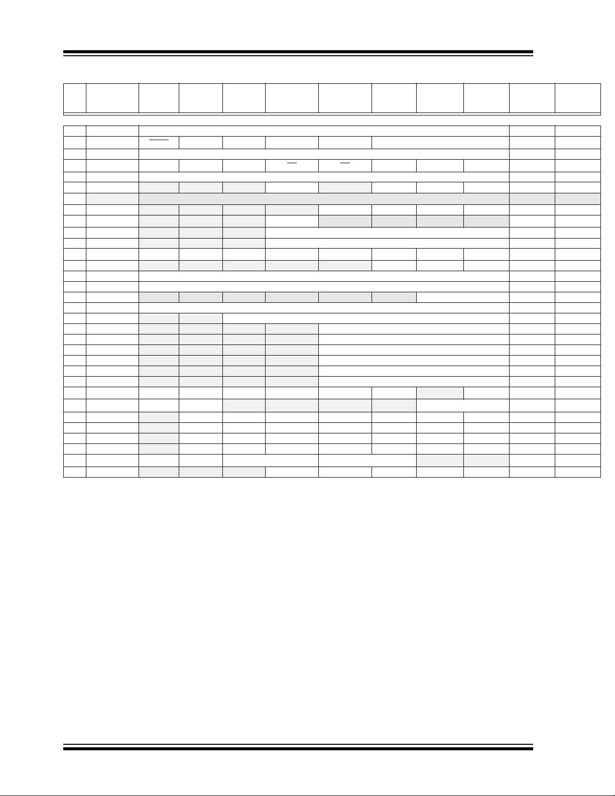
TABLE 1: PIC16F753/HV753 FAMILY TYPES
Device
Flash (words)
Data Sheet Index
Program Memory
PIC12F752 (1) 1K Y 64 6 4 2 3/1 1 Y 5-bit N N H
PIC12HV752 (1) 1K Y 64 6 4 2 3/1 1 Y 5-bit N Y H
PIC16F753 (2) 2K Y 128 12 8 2 3/1 1 Y 9-bit Y N I/H
PIC16HV753 (2) 2K Y 128 12 8 2 3/1 1 Y 9-bit Y Y I/H
Note 1: I - Debugging, Integrated on Chip; H - Debugging, Requires Debug Header.
2: One pin is input-only.
Data Sheet Index: (Unshaded devices are described in this document.)
1: DS41576 PIC12F752/HV752 Data Sheet, 8-Pin Flash-Based, 8-Bit CMOS Microcontrollers.
2: DS40001709 PIC16F753/HV753 Data Sheet, 14/16-Pin Flash-based, 8-Bit CMOS Microcontrollers.
Note: For other small form-factor package availability and marking information, please visit
http://www.microchip.com/packaging or contact your local sales office.
Self Read/Write
Data SRAM
Flash Memory
(2)
I/Os
(bytes)
10-bit ADC (ch)
Timers
Comparators
(8/16-bit)
CCP
Complementary
Output Generator
DAC
(COG)
Op Amp
Shunt Regulator
Pin Diagram – 14-Pin PDIP, SOIC, TSSOP
(1)
Debug
DS40001709B-page 2 Preliminary 2013 Microchip Technology Inc.

PIC16F753/HV753
Note: See Tab le 2 for location of all peripheral functions.
78
2
3
1
11
12
5
9
10
13141516
6
4
RA5
RA4
MCLR
/VPP/RA3
RC4
RC3
RC1
RC2
RC0
RA0/ICSPDAT
RA2
RA1/ICSPCLK
Vss
VDD
NC
RC5
NC
PIC16F753/HV753
(4x4)
Pin Diagram – 16-Pin QFN
TABLE 2: 14/16-PIN ALLOCATION TABLE FOR PIC16F753/HV753
I/O
14-Pin PDIP/SOIC/TSSOP
RA0 13 12 AN0 FVROUT
RA1 12 11 AN1 VREF+
RA2 11 10 AN2 COG1FLT — C1OUT T0CKI — INT
RA3 4 3 — — — — T1G
RA4 3 2 AN3 — — — T1G
RA5 2 1 — — — — T1CKI — IOC Y — CLKIN
RC0 10 9 AN4 — OPA1IN+ C2IN0+ — — IOC — — —
RC1 9 8 AN5 — OPA1IN- C1IN1-
RC2 8 7 AN6 — OPA1OUT C1IN2-
RC3 7 6 AN7 — — C1IN3-
RC4 6 5 — COG1OUT1 — C2OUT — — IOC — — —
RC5 5 4 — COG1OUT0 — — — CCP1 IOC — — —
VDD 1 16 — — — — — — — — — VDD
VSS 14 13 — — — — — — — — — VSS
Note 1: Default location for peripheral pin function. Alternate location can be selected using the APFCON register.
2: Alternate location for peripheral pin function selected by the APFCON register.
16-Pin QFN
ADC
Reference
DACOUT
FVRIN
Op Amp
— C1IN0+ — — IOC Y — ICSPDAT
— C1IN0-
Comparator
C2IN0-
C2IN1-
C2IN2-
C2IN3-
Timer
— — IOC Y — ICSPCLK
(2)
(1)
— — IOC — — —
— — IOC — SLPCIN —
— — IOC — — —
CCP
IOC
— IOC Y — MCLR/
— IOC Y — CLKOUT
Pull-up
Interrupt
Y — —
Slope Compensation
Basic
PP
V
2013 Microchip Technology Inc. Preliminary DS40001709B-page 3

PIC16F753/HV753
Table of Contents
1.0 Device Overview ......................................................................................................................................................................... 6
2.0 Memory Organization .................................................................................................................................................................. 9
3.0 Flash Program Memory Self Read/Self Write Control ............................................................................................................... 25
4.0 Oscillator Module ....................................................................................................................................................................... 34
5.0 I/O Ports .................................................................................................................................................................................... 39
6.0 Timer0 Module .......................................................................................................................................................................... 54
7.0 Timer1 Module with Gate Control .............................................................................................................................................. 57
8.0 Timer2 Module .......................................................................................................................................................................... 68
9.0 Hardware Limit Timer (HLT) Module ......................................................................................................................................... 70
10.0 Capture/Compare/PWM Modules ............................................................................................................................................. 74
11.0 Complementary Output Generator (COG) Module .................................................................................................................... 81
12.0 Analog-to-Digital Converter (ADC) Module ............................................................................................................................. 104
13.0 Fixed Voltage Reference (FVR) .............................................................................................................................................. 115
14.0 Digital-to-Analog Converter (DAC) Module ............................................................................................................................. 117
15.0 Comparator Module ................................................................................................................................................................. 123
16.0 Operational Amplifier (OPA) Module ....................................................................................................................................... 132
17.0 Slope Compensator.................................................................................................................................................................. 135
18.0 Instruction Set Summary ......................................................................................................................................................... 140
19.0 Special Features of the CPU ................................................................................................................................................... 149
20.0 Shunt Regulator (PIC16HV753 Only) ...................................................................................................................................... 168
21.0 Development Support .............................................................................................................................................................. 169
22.0 Electrical Specifications ........................................................................................................................................................... 173
23.0 DC and AC Characteristics Graphs and Charts ...................................................................................................................... 197
24.0 Packaging Information ............................................................................................................................................................. 216
The Microchip Web Site .................................................................................................................................................................... 228
Customer Change Notification Service ............................................................................................................................................. 228
Customer Support ............................................................................................................................................................................. 228
Product Identification System ............................................................................................................................................................ 229
DS40001709B-page 4 Preliminary 2013 Microchip Technology Inc.

PIC16F753/HV753
TO OUR VALUED CUSTOMERS
It is our intention to provide our valued customers with the best documentation possible to ensure successful use of your Microchip
products. To this end, we will continue to improve our publications to better suit your needs. Our publications will be refined and
enhanced as new volumes and updates are introduced.
If you have any questions or comments regarding this publication, please contact the Marketing Communications Department via
E-mail at docerrors@microchip.com. We welcome your feedback.
Most Current Data Sheet
To obtain the most up-to-date version of this data sheet, please register at our Worldwide Web site at:
http://www.microchip.com
You can determine the version of a data sheet by examining its literature number found on the bottom outside corner of any page.
The last character of the literature number is the version number, (e.g., DS30000000A is version A of document DS30000000).
Errata
An errata sheet, describing minor operational differences from the data sheet and recommended workarounds, may exist for current
devices. As device/documentation issues become known to us, we will publish an errata sheet. The errata will specify the revision
of silicon and revision of document to which it applies.
To determine if an errata sheet exists for a particular device, please check with one of the following:
• Microchip’s Worldwide Web site; http://www.microchip.com
• Your local Microchip sales office (see last page)
When contacting a sales office, please specify which device, revision of silicon and data sheet (include literature number) you are
using.
Customer Notification System
Register on our web site at www.microchip.com to receive the most current information on all of our products.
2013 Microchip Technology Inc. Preliminary DS40001709B-page 5

PIC16F753/HV753
Flash
Program
Memory
13
Data Bus
8
14
Program
Bus
Instruction Reg
Program Counter
RAM
File
Registers
Direct Addr
7
RAM Addr
9
Addr MUX
Indirect
Addr
FSR Reg
STATUS Reg
MUX
ALU
W Reg
Instruction
Decode &
Control
Timing
Generation
CLKIN
CLKOUT
PORTA
8
8
8
3
8-Level Stack
64 Bytes
2K X 14
(13-Bit)
Power-up
Timer
Power-on
Reset
Watchdog
Timer
MCLR
VSS
Brown-out
Reset
Timer0 Timer1
RA0
RA1
RA2
RA3
RA4
RA5
Analog Comparator
T0CKI
INT
T1CKI
Configuration
Internal
Oscillator
and Reference
T1G
VDD
Block
C1IN0+/C2IN0+
C1IN0-/C2IN0-
C1IN1-
C2IN1-
C1OUT/C2OUT
Shunt Regulator
(PIC16HV753 only)
Capture/
Compare/
PWM
(CCP)
Hardware
Limit
Timer1
(HLT)
Complementary
Output
Generator
(COG)
Timer2
Fixed Voltage
Reference
(FVR)
Dual Range
DAC
PORTC
RC0
RC1
RC2
RC3
RC4
RC5
Op. Amp.
Slope
Compensator
1.0 DEVICE OVERVIEW
Block Diagrams and pinout descriptions of the devices
are shown in Figure 1-1 and Ta bl e 1- 1.
The PIC16F753/HV753 devices are covered by this
data sheet. They are available in 14-pin PDIP, SOIC,
TSSOP and 16-pin QFN packages.
FIGURE 1-1: PIC16F753/HV753 BLOCK DIAGRAM
DS40001709B-page 6 Preliminary 2013 Microchip Technology Inc.

PIC16F753/HV753
TABLE 1-1: PIC16F753/HV753 PINOUT DESCRIPTION
Name Function
RA0/AN0/C1IN0+/DACOUT/
FVROUT/ICSPDAT
RA1/AN1/C1IN0-/C2IN0-/
REF+/FVRIN/ICSPCLK
V
RA2/AN2/INT/C1OUT/
T0CKI/COG1FLT
(1)
(3)
/T1G
RA3
RA4/AN3/T1G
RA5/T1CKI/COG1OUT0
C2IN1-/CLKIN
RC0/AN4/OPA1IN+/C2IN0+ RC0 TTL CMOS General purpose I/O with IOC and WPU.
RC1/AN5/OPA1IN-/C1IN1-/
C2IN1-
Legend: AN = Analog input or output CMOS = CMOS compatible input or output
Note 1: Input only.
/VPP/MCLR
(2)
/CLKOUT RA4 TTL CMOS General purpose I/O with IOC and WPU.
TTL = TTL compatible input ST = Schmitt Trigger input with CMOS levels
HP = High Power HV = High Voltage
* Alternate pin function.
2: Default pin function via the APFCON register.
3: Alternate pin function via the APFCON register.
4: RA3 pull-up is enabled when pin is configured as MCLR
(4)
(3)
RA0 TTL HP General purpose I/O with IOC and WPU.
AN0 AN — A/D Channel 0 input.
C1IN0+ AN — Comparator C1 positive input.
DACOUT — AN DAC unbuffered Voltage Reference output.
FVROUT — AN DAC/FVR buffered Voltage Reference output.
ICSPDAT ST HP Serial Programming Data I/O.
RA1 TTL CMOS General purpose I/O with IOC and WPU.
AN1 AN — A/D Channel 1 input.
C1IN0- AN — Comparator C1 negative input.
C2IN0- AN — Comparator C2 negative input.
REF+ AN — A/D Positive Voltage Reference input.
V
FVRIN AN — Voltage reference input.
ICSPCLK ST — Serial Programming Clock.
RA2 ST HP General purpose I/O with IOC and WPU.
AN2 AN — A/D Channel 2 input.
INT ST — External interrupt.
C1OUT — HP Comparator C1 output.
T0CKI ST — Timer0 clock input.
COG1FLT ST — COG auto-shutdown fault input.
RA3 TTL — General purpose input with WPU.
T1G ST — Timer1 Gate input.
PP HV — Programming voltage.
V
MCLR
AN3 AN — A/D Channel 3 input.
T1G ST — Timer1 Gate input.
CLKOUT — CMOS F
/
RA5 TTL CMOS General purpose I/O with IOC and WPU.
T1CKI ST — Timer1 clock input.
CLKIN ST — External Clock input (EC mode).
AN4 AN — A/D Channel 4 input.
OPA1IN+ AN — Op amp positive input.
C2IN0+ AN — Comparator C2 positive input.
RC1 TTL CMOS General purpose I/O with IOC and WPU.
AN5 AN — A/D Channel 5 input.
OPA1IN- AN — Op amp negative input.
C1IN1- AN — Comparator C1 negative input.
C2IN1- AN — Comparator C2 negative input.
Input
Type
ST
Output
Typ e
—
Description
Master Clear w/internal pull-up.
OSC/4 output.
in Configuration Word.
2013 Microchip Technology Inc. Preliminary DS40001709B-page 7

PIC16F753/HV753
TABLE 1-1: PIC16F753/HV753 PINOUT DESCRIPTION (CONTINUED)
Name Function
RC2/AN6/SLPCIN/
OPA1OUT/C1IN2-/C2IN2-
RC3/AN7/C1IN3-/C2IN3- RC3 TTL CMOS General purpose I/O with IOC and WPU.
RC4/COG1OUT1/C2OUT RC4 TTL CMOS General purpose I/O with IOC and WPU.
RC5/COG1OUT0/CCP1 RC5 TTL CMOS General purpose I/O with IOC and WPU.
DD VDD Power — Positive supply.
V
V
SS VSS Power — Ground reference.
Legend: AN = Analog input or output CMOS = CMOS compatible input or output
Note 1: Input only.
TTL = TTL compatible input ST = Schmitt Trigger input with CMOS levels
HP = High Power HV = High Voltage
* Alternate pin function.
2: Default pin function via the APFCON register.
3: Alternate pin function via the APFCON register.
4: RA3 pull-up is enabled when pin is configured as MCLR
RC2 TTL CMOS General purpose I/O with IOC and WPU.
AN6 AN — A/D Channel 6 input.
OPA1OUT AN HP Op amp output.
C1IN2- AN — Comparator C1 negative input.
C2IN2- AN — Comparator C2 negative input.
AN7 AN — A/D Channel 7 input.
C1IN3- AN — Comparator C1 negative input.
C2IN3- AN — Comparator C2 negative input.
COG1OUT1 — CMOS COG output Channel 1.
C2OUT — HP Comparator C2 output.
COG1OUT0 — CMOS COG output Channel 0.
CCP1 — HP Capture/Compare/PWM 1.
Input
Type
Output
Typ e
Description
in Configuration Word.
DS40001709B-page 8 Preliminary 2013 Microchip Technology Inc.

PIC16F753/HV753
PC<12:0>
13
0000h
0004h
0005h
07FFh
0400h
1FFFh
Stack Level 1
Stack Level 8
Reset Vector
Interrupt Vector
On-chip Program
Memory
CALL, RETURN
RETFIE, RETLW
Stack Level 2
Shadows 0-07FFh
2.0 MEMORY ORGANIZATION
2.1 Program Memory Organization
The PIC16F753/HV753 has a 13-bit program counter
capable of addressing an 8K x 14 program memory
space. Only the first 2K x 14 (0000h-07FFh) is
physically implemented. Accessing a location above
these boundaries will cause a wrap-around within the
first 2K x 14 space for PIC16F753/HV753. The Reset
vector is at 0000h and the interrupt vector is at 0004h
(see Figure 2-1).
FIGURE 2-1: PROGRAM MEMORY MAP
AND STACK FOR THE
PIC16F753/HV753
2.2 Data Memory Organization
The data memory (see Figure 2-2) is partitioned into four
banks, which contain the General Purpose Registers
(GPR) and the Special Function Registers (SFR). The
Special Function Registers are located in the first 32
locations of each bank. Register locations 40h-6Fh in
Bank 0 are General Purpose Registers, implemented as
static RAM. Register locations 70h-7Fh in Bank 0 are
Common RAM and shared as the last 16 addresses in
all Banks. All other RAM is unimplemented and returns
‘0’ when read. The RP<1:0> bits of the STATUS register
are the bank select bits.
RP0
RP1
00 Bank 0 is selected
01 Bank 1 is selected
10 Bank 2 is selected
11 Bank 3 is selected
2.2.1 GENERAL PURPOSE REGISTER FILE
The register file is organized as 64 x 8 in the
PIC16F753/HV753. Each register is accessed, either
directly or indirectly, through the File Select Register
(FSR) (see Section 2.5 “Indirect Addressing, INDF
and FSR Registers”).
2.2.2 SPECIAL FUNCTION REGISTERS
The Special Function Registers are registers used by
the CPU and peripheral functions for controlling the
desired operation of the device (see Tab le 2 -1 ). These
registers are static RAM.
The special registers can be classified into two sets:
core and peripheral. The Special Function Registers
associated with the “core” are described in this section.
Those related to the operation of the peripheral features
are described in the section of that peripheral feature.
2013 Microchip Technology Inc. Preliminary DS40001709B-page 9

PIC16F753/HV753
Legend: = Unimplemented data memory locations, read as ‘0’.
BANK 0 BANK 1 BANK 2 BANK 3
INDF 00h INDF 80h INDF 100h INDF 180h
TMR0 01h OPTION_REG 81h TMR0 101h OPTION_REG 181h
PCL 02h PCL 82h PCL 102h PCL 182h
STATUS 03h STATUS 83h STATUS 103h STATUS 183h
FSR 04h FSR 84h FSR 104h FSR 184h
PORTA 05h TRISA 85h LATA 105h ANSELA 185h
—06h —86h — 106h — 186h
PORTC 07h TRISC 87h LATC 107h ANSELC 187h
IOCAF 08h IOCAP 88h IOCAN 108h APFCON 188h
IOCCF 09h IOCCP 89h IOCCN 109h OSCTUNE 189h
PCLATH 0Ah PCLATH 8Ah PCLATH 10Ah PCLATH 18Ah
INTCON 0Bh INTCON 8Bh INTCON 10Bh INTCON 18Bh
PIR1 0Ch PIE1 8Ch WPUA 10Ch
PMCON1 18Ch
PIR2 0Dh PIE2 8Dh WPUC 10Dh
PMCON2 18Dh
—0Eh — 8Eh SLRCONC 10Eh PMADRL 18Eh
TMR1L 0Fh OSCCON 8Fh PCON 10Fh
PMADRH 18Fh
TMR1H 10h
FVR1CON0 90h TMR2 110h PMDATL 190h
T1CON 11h DAC1CON0 91h
PR2 111h PMDATH 191h
T1GCON 12h
DAC1REFL 92h T2CON 112h COG1PHR 192h
CCPR1L 13h
DAC1REFH 93h HLTMR1 113h COG1PHF 193h
CCPR1H 14h
—94h HLTPR1 114h COG1BKR 194h
CCP1CON 15h
—95h HLT1CON0 115h COG1BKF 195h
—16h OPA1CON0 96h HLT1CON1 116h COG1DBR 196h
—17h —97h HLTMR2 117h COG1DBF 197h
—18h — 98h HLTPR2 118h COG1CON0 198h
—19h — 99h HLT2CON0 119h COG1CON1 199h
—1Ah — 9Ah HLT2CON1 11Ah COG1RIS 19Ah
— 1Bh CM2CON0 9Bh — 11Bh COG1RSIM 19Bh
ADRESL 1Ch CM2CON1 9Ch
— 11Ch COG1FIS 19Ch
ADRESH 1Dh CM1CON0 9Dh
— 11Dh COG1FSIM 19Dh
ADCON0 1Eh CM1CON1 9Eh SLPCCON0 11Eh COG1ASD0 19Eh
ADCON1 1Fh CMOUT 9Fh SLPCCON1 11Fh COG1ASD1 19Fh
General
Purpose
Register
80 Bytes
20h
General Purpose
Register
32 Bytes
A0h
BFh
Unimplemented
Read as ‘0’
120h
Unimplemented
Read as ‘0’
1A0h
Unimplemented
Read as ‘0’
C0h
EFh
6Fh
16Fh
170h
17Fh
1EFh
1F0h
1FFh
Common RAM
16 Bytes
70h
7Fh
Common RAM
(Accesses
70h – 7Fh)
F0h
FFh
Common RAM
(Accesses
70h – 7Fh)
Common RAM
(Accesses
70h – 7Fh)
FIGURE 2-2: DATA MEMORY MAP OF THE PIC16F753/HV753
DS40001709B-page 10 Preliminary 2013 Microchip Technology Inc.

PIC16F753/HV753
TABLE 2-1: PIC16F753/HV753 SPECIAL REGISTERS SUMMARY BANK 0
Addr Name Bit 7 Bit 6 Bit 5 Bit 4 Bit 3 Bit 2 Bit 1 Bit 0
Bank 0
00h INDF INDF<7:0> xxxx xxxx xxxx xxxx
01h TMR0 TMR0<7:0> xxxx xxxx uuuu uuuu
02h PCL PCL<7:0> 0000 0000 0000 0000
03h STATUS
04h FSR FSR<7:0> xxxx xxxx uuuu uuuu
05h PORTA
06h
— Unimplemented — —
07h PORTC
08h IOCAF
09h IOCCF
0Ah PCLATH
0Bh INTCON GIE PEIE T0IE INTE IOCIE T0IF INTF IOCIF 0000 0000 0000 0000
0Ch PIR1
0Dh PIR2
— Unimplemented — —
0Eh
0Fh
TMR1L TMR1L<7:0> xxxx xxxx uuuu uuuu
10h
TMR1H TMR1H<7:0> xxxx xxxx uuuu uuuu
11h
T1CON
12h
T1GCON
13h
CCPR1L CCPR1L<7:0>
14h
CCPR1H CCPR1H<7:0>
15h
CCP1CON
— Unimplemented — —
16h
17h
— Unimplemented — —
18h
— Unimplemented — —
— Unimplemented — —
19h
1Ah
— Unimplemented — —
1Bh
— Unimplemented — —
ADRESL Least Significant two bits of the left shifted result or eight bits of the right shifted result xxxx xxxx uuuu uuuu
1Ch
1Dh ADRESH Most Significant eight bits of the left shifted A/D result or two bits of the right shifted result xxxx xxxx uuuu uuuu
1Eh ADCON0 ADFM
1Fh
ADCON1
Legend: — = Unimplemented locations read as ‘0’, u = unchanged, x = unknown, q = value depends on condition shaded = unimplemented.
IRP RP1 RP0 TO
— —
— —
— —
— —
— — — PCLATH<4:0> ---0 0000 ---0 0000
TMR1GIF ADIF — — HLTMR2IF HLTMR1IF TMR2IF TMR1IF 00--0000 00--0000
— — C2IF C1IF — COG1IF — CCP1IF --00 -0-0 --00 -0-0
TMR1CS<1:0> T1CKPS<1:0> T1OSCEN T1SYNC
TMR1GE T1GPOL T1GTM T1GSPM T1GGO/
— —
—
— ADCS<2:0> — — —
RA5 RA4 RA3 RA2 RA1 RA0
RC5 RC4 RC3 RC2 RC1 RC0
IOCAF5 IOCAF4 IOCAF3 IOCAF2 IOCAF1 IOCAF0
IOCCF5 IOCCF4 IOCCF3 IOCCF2 IOCCF1 IOCCF0
DC1B<1:0> CCP1M<3:0>
CHS<3:0> GO/DONE
PD ZDCC
—
TMR1ON 0000 00-0 0000 00-0
DONE
T1GVAL T1GSS<1:0>
ADON
ADPREF1 -000 ---0 -000 ---0
Value on
POR/BOR
0001 1xxx 000q quuu
--xx xxxx --uu uuuu
--xx xxxx --uu uuuu
--00 0000 --00 0000
--00 0000 --00 0000
0000 0x00 0000 0x00
xxxx xxxx
xxxx xxxx
--00 0000 --00 0000
0-00 0000 0-00 0000
Value on
all other
Resets
uuuu uuuu
uuuu uuuu
2013 Microchip Technology Inc. Preliminary DS40001709B-page 11

PIC16F753/HV753
TABLE 2-2: PIC16F753/HV753 SPECIAL REGISTERS SUMMARY BANK 1
Addr Name Bit 7 Bit 6 Bit 5 Bit 4 Bit 3 Bit 2 Bit 1 Bit 0
Bank 1
80h INDF INDF<7:0> xxxx xxxx uuuu uuuu
81h OPTION_REG
82h PCL PCL<7:0> 0000 0000 0000 0000
83h STATUS
84h FSR FSR xxxx xxxx uuuu uuuu
85h TRISA — — TRISA5 TRISA4 TRISA3 TRISA2 TRISA1 TRISA0 --11 1111 --11 1111
86h — Unimplemented — —
87h TRISC — — TRISC5 TRISC4 TRISC3 TRISC2 TRISC1 TRISC0 --11 1111 --11 1111
88h IOCAP — — IOCAP5 IOCAP4 IOCAP3 IOCAP2 IOCAP1 IOCAP0 --00 0000 --00 0000
89h IOCCP — — IOCCP5 IOCCP4 IOCCP3 IOCCP2 IOCCP1 IOCCP0 --00 0000 --00 0000
8Ah PCLATH — — —PCLATH<4:0>---0 0000 ---0 0000
8Bh INTCON GIE PEIE T0IE INTE IOCIE T0IF INTF IOCIF 0000 0000 0000 0000
8Ch PIE1 TMR1GIE ADIE — — HLTMR2IE HLTMR1IE TMR2IE TMR1IE 00-- 0000 00-- 0000
8Dh PIE2 — — C2IE C1IE — COG1IE — CCP1IE --00 -0-0 --00 -0-0
8Eh — Unimplemented — —
8Fh OSCCON
90h FVR1CON0 FVREN FVRRDY FVROE FVRBUFSS1 FVRBUFSS0 — — FVRBUFEN 0000 0--0 0000 0--0
91h DAC1CON0 DACEN DACFM DACOE — DACPSS1 DACPSS0 — — 000- 00-- 000- 00--
92h DAC1REFL Least Significant bit of the left shifted result or eight bits of the right shifted DAC setting 0000 0000 0000 0000
93h DAC1REFH
94h — Unimplemented — —
95h
— Unimplemented — —
96h OPA1CON OPA1EN — — OPA1UGM OPA1NCH<1:0> OPA1PCH<1:0> 0--0 0000 0--0 0000
97h
— Unimplemented — —
98h — Unimplemented — —
99h
— Unimplemented — —
9Ah — Unimplemented — —
9Bh CM2CON0 C2ON C2OUT C2OE C2POL C2ZLF C2SP C2HYS C2SYNC 0000 0100 0000 0100
9Ch CM2CON1 C2INTP C2INTN C2PCH<2:0> C2NCH<2:0> 0000 0000 0000 0000
9Dh CM1CON0 C1ON C1OUT C1OE C1POL C1ZLF C1SP C1HYS C1SYNC 0000 0100 0000 0100
9Eh CM1CON1 C1INTP C1INTN C1PCH<2:0> C1NCH<2:0> 0000 0000 0000 0000
9Fh CMOUT — — — — — — MCOUT2 MCOUT1 ---- --00 ---- --00
Legend: — = Unimplemented locations read as ‘0’, u = unchanged, x = unknown, q = value depends on condition shaded = unimplemented.
RAPU
IRP RP1 RP0 TO
INTEDG T0CS T0SE PSA PS<2:0>
PD ZDC C
— —
Most Significant eight bits of the left shifted DAC setting or first bit of the right shifted result 0000 0000 0000 0000
IRCF<1:0>
—
HTS LTS
—
Value on
POR/BOR
1111 1111 1111 1111
0001 1xxx 000q quuu
--01 -00- --uu -uu-
Values on
all other
Resets
DS40001709B-page 12 Preliminary 2013 Microchip Technology Inc.

PIC16F753/HV753
TABLE 2-3: PIC16F753/HV753 SPECIAL REGISTERS SUMMARY BANK 2
Addr Name Bit 7 Bit 6 Bit 5 Bit 4 Bit 3 Bit 2 Bit 1 Bit 0
Bank 2
100h INDF
101h TMR0
102h PCL
103h STATUS
104h FSR
105h LATA — —LATA5LATA4— LATA 2 LAT A1 L ATA0 --xx -xxx --uu -uuu
106h — Unimplemented — —
107h LATC — — LATC5 LATC4 LATC3 LATC2 LATC1 LATC0 --xx xxxx --uu uuuu
108h IOCAN — — IOCAN5 IOCAN4 IOCAN3 IOCAN2 IOCAN1 IOCAN0 --00 0000 --00 0000
109h IOCCN — — IOCCN5 IOCCN4 IOCCN3 IOCCN2 IOCCN1 IOCCN0 --00 0000 --00 0000
10Ah PCLATH
10Bh INTCON
10Ch WPUA — — WPUA5 WPUA4 WPUA3 WPUA2 WPUA1 WPUA0 --11 1111 --11 1111
10Dh WPUC — — WPUC5 WPUC4 WPUC3 WPUC2 WPUC1 WPUC0 --11 1111 --11 1111
10Eh SLRCONC — — SLRC5 SLRC4 — — — — --00 ---- --00 ----
10Fh PCON — — — — — —PORBOR ---- --qq ---- --uu
110h
TMR2 TMR2<7:0> 0000 0000 0000 0000
111h PR2 PR2<7:0> 1111 1111 1111 1111
112 h T 2CO N — T2OUTPS<3:0> TMR2ON T2CKPS<1:0> -000 0000 -000 0000
113h HLTMR1 Holding Register for the 8-bit Hardware Limit Timer1 Count 0000 0000 0000 0000
114h HLTPR1 HLTMR1 Module Period Register 1111 1111 1111 1111
115h HLT1CON0 — H1OUTPS<3:0> H1ON H1CKPS<1:0> -000 0000 -000 0000
116h HLT1CON1 H1FES H1RES — H1ERS<2:0> H1FEREN H1REREN 11-0 0000 11-0 0000
117 h
HLTMR2 Holding Register for the 8-bit Hardware Limit Timer2 Count 0000 0000 0000 0000
118 h
HLTPR2 HLTMR2 Module Period Register 1111 1111 1111 1111
119 h
HLT2CON0
11A h
HLT2CON1 H2FES H2RES
11B h
— Unimplemented — —
11C h
— Unimplemented — —
11D h
— Unimplemented — —
11E h
SLPCCON0 SC1EN
11F h
SLPCCON1
Legend: — = Unimplemented locations read as ‘0’, u = unchanged, x = unknown, q = value depends on condition shaded = unimplemented.
IRP RP1 RP0 TO
— — —PCLATH<4:0>---0 0000 ---0 0000
GIE PEIE T0IE INTE IOCIE T0IF INTF IOCIF 0000 0000 0000 0000
— H2OUTPS<3:0> H2ON H2CKPS<1:0> -000 0000 -000 0000
— H2ERS<2:0> H2FEREN H2REREN 11-0 0000 11-0 0000
— — SC1POL SC1TSS<1:0> —SC1INS0-00 00-0 0-00 00-0
— — — SC1RNG SC1ISET<3:0> ---0 0000 ---0 0000
INDF<7:0>
TMR0<7:0>
PCL<7:0>
PD ZDC C
FSR<7:0>
Val ue o n
POR/BOR
xxxx xxxx xxxx xxxx
xxxx xxxx uuuu uuuu
0000 0000 0000 0000
0001 1xxx 000q quuu
xxxx xxxx uuuu uuuu
Valu e o n
all other
Resets
2013 Microchip Technology Inc. Preliminary DS40001709B-page 13
PIC16F753/HV753
TABLE 2-4: PIC16F753/HV753 SPECIAL FUNCTION REGISTERS SUMMARY BANK 3
Addr Name Bit 7 Bit 6 Bit 5 Bit 4 Bit 3 Bit 2 Bit 1 Bit 0
Bank 3
180h INDF INDF<7:0> xxxx xxxx uuuu uuuu
181h OPTION_REG
182h PCL PCL<7:0> 0000 0000 0000 0000
183h STATUS
184h FSR FSR<7 :0> xxxx xxxx uuuu uuuu
185h ANSELA — — —ANSA4 — ANSA2 ANSA1 ANSA0 ---1 -111 ---1 -111
186h
—
187h ANSELC — — — — ANSC3 ANSC2 ANSC1 ANSC0 ---- 0000 ---- 0000
188h APFCON
189h OSCTUNE — — — TUN<4:0> ---0 0000 ---0 0000
18Ah PCLATH — — — PCLATH<4:0> ---0 0000 ---0 0000
18Bh INTCON GIE PEIE T0IE INTE IOCIE T0IF INTF IOCIF
18Ch PMCON1 — — — — —WRENWR RD---- -000 ---- -000
18Dh PMCON2 Program Memory Control Register 2 ---- ---- ---- ----
18Eh PMADRL PMADRL<7:0> 0000 0000 0000 0000
18Fh PMADRH — — — — — — PMADRH<1:0> ---- --00 ---- --00
190h PMDATL PMDATL<7:0> 0000 0000 0000 0000
191h PMDATH — —PMDATH<5:0>--00 0000 --00 0000
192h COG1PHR — — — — G1PHR<3:0> ---- xxxx ---- uuuu
193h COG1PHF — — — —G1PHF<3:0>---- xxxx ---- uuuu
194h COG1BKR — — — — G1BKR<3:0> ---- xxxx ---- uuuu
195h COG1BKF — — — — G1BKF<3:0> ---- xxxx ---- uuuu
196h COG1DBR — — — —G1DBR<3:0>---- xxxx ---- uuuu
197h COG1DBF — — — —G1DBF<3:0>---- xxxx ---- uuuu
198h COG1CON0 G1EN G1OE1 G1OE0 G1POL1 G1POL0 G1LD
199h COG1CON1 G1RDBTS G1FDBTS
19Ah COG1RIS
19Bh COG1RSIM — G1RMHLT2 G1RMHLT1 G1RMT2M G1RMFLT G1RMCCP1 G1RMC2 G1RMC1 0000 0000 0000 0000
19Ch COG1FIS
19Dh COG1FSIM — G1FMHLT2 G1FMHLT1 G1FMT2M G1FMFLT G1FMCCP1 G1FMC2 G1FMC1 0000 0000 0000 0000
19Eh COG1ASD0 C1ASDE C1ARSEN G1ASD1L<1:0> G1ASD0L<1:0>
19Fh COG1ASD1
Legend: — = Unimplemented locations read as ‘0’, u = unchanged, x = unknown, q = value depends on condition shaded = unimplemented
RAPU
IRP RP1 RP0 TO
— — —
— G1RIHLT2 G1RIHLT1 G1RIT2M G1RIFLT G1RICCP1 G1RIC2 G1RIC1 0000 0000 0000 0000
— G1FIHLT2 G1FIHLT1 G1FIT2M G1FIFLT G1FICCP1 G1FIC2 G1FIC1 0000 0000 0000 0000
— — — G1ASDSHLT2 G1ASDSHLT1 G1ASDSC2 G1ASDSC1 G1ASDSFLT 0000 0000 0000 0000
INTEDG T0CS T0SE PSA PS<2:0>
PD ZDCC
Unimplemented
T1GSEL
— — — —
— — — — ---0 ---- ---0 ----
—
G1CS<1:0> 00-- --00 00-- --00
— —
G1MD 0000 00-0 0000 00-0
Val ue o n
POR/BOR
1111 1111 1111 1111
0001 1xxx 000q quuu
— —
0000 0000 0000 0000
0000 00-- 0000 00--
Values on
all other
Resets
DS40001709B-page 14 Preliminary 2013 Microchip Technology Inc.

PIC16F753/HV753
2.3 Global SFRs
writable. Therefore, the result of an instruction with the
STATUS register as destination may be different than
2.3.1 STATUS REGISTER
The STATUS register, shown in Register 2-1, contains:
• the arithmetic status of the ALU
• the Reset status
• the bank select bits for data memory (RAM)
The STATUS register can be the destination for any
instruction, like any other register. If the STATUS
register is the destination for an instruction that affects
the Z, DC or C bits, then the write to these three bits is
intended.
For example, CLRF STATUS, will clear the upper three
bits and set the Z bit. This leaves the STATUS register
as ‘000u u1uu’ (where u = unchanged).
It is recommended, therefore, that only BCF, BSF,
SWAPF and MOVWF instructions are used to alter the
STATUS register, because these instructions do not
affect any Status bits. For other instructions not
affecting any Status bits, see Section 18.0
“Instruction Set Summary”.
disabled. These bits are set or cleared according to the
device logic. Furthermore, the TO
and PD bits are not
REGISTER 2-1: STATUS: STATUS REGISTER
R/W-0 R/W-0 R/W-0 R-1 R-1 R/W-x R/W-x R/W-x
IRP RP1 RP0 TO
bit 7 bit 0
Legend:
R = Readable bit W = Writable bit U = Unimplemented bit, read as ‘0’
-n = Value at POR ‘1’ = Bit is set ‘0’ = Bit is cleared x = Bit is unknown
PD ZDC
(1)
(1)
C
bit 7 IRP: Register Bank Select bit (used for indirect addressing)
1 = Bank 2, 3 (100h-1FFh)
0 = Bank 0, 1 (00h-FFh)
bit 6 RP1: Register Bank Select bit (used for direct addressing)
00 = Bank 0 (00h-7Fh)
01 = Bank 1 (80h-FFh)
10 = Bank 2 (100h-17Fh)
11 = Bank 3 (180h-1FFh)
bit 5 RP0: Register Bank Select bit (used for direct addressing)
1 = Bank 1 (80h-FFh)
0 = Bank 0 (00h-7Fh)
bit 4 TO
bit 3 PD
bit 2 Z: Zero bit
bit 1 DC: Digit Carry/Borrow
bit 0 C: Carry/Borrow
: Time-Out bit
1 = After power-up, CLRWDT instruction or SLEEP instruction
0 = A WDT time-out occurred
: Power-Down bit
1 = After power-up or by the CLRWDT instruction
0 = By execution of the SLEEP instruction
1 = The result of an arithmetic or logic operation is zero
0 = The result of an arithmetic or logic operation is not zero
1 = A carry-out from the 4th low-order bit of the result occurred
0 = No carry-out from the 4th low-order bit of the result
bit
1 = A carry-out from the Most Significant bit of the result occurred
0 = No carry-out from the Most Significant bit of the result occurred
(2)
bit
(ADDWF, ADDLW,SUBLW,SUBWF instructions), For Borrow, the polarity is reversed.
(2)
(ADDWF, ADDLW, SUBLW, SUBWF instructions)
Note 1: The C and DC bits operate as a Borrow
instructions for examples.
2: For Borrow
For rotate (RRF, RLF) instructions, this bit is loaded with either the high-order or low-order bit of the source register.
2013 Microchip Technology Inc. Preliminary DS40001709B-page 15
, the polarity is reversed. A subtraction is executed by adding the two’s complement of the second operand.
and Digit Borrow out bit, respectively, in subtraction. See the SUBLW and SUBWF

PIC16F753/HV753
000
001
010
011
100
101
110
111
1 : 2
1 : 4
1 : 8
1 : 16
1 : 32
1 : 64
1 : 128
1 : 256
1 : 1
1 : 2
1 : 4
1 : 8
1 : 16
1 : 32
1 : 64
1 : 128
BIT VALUE TIMER0 RATE WDT RATE
2.3.2 OPTION REGISTER
The OPTION register is a readable and writable
register, which contains various control bits to
configure:
• Timer0/WDT prescaler
• External RA2/INT interrupt
•Timer0
• Weak pull-ups on PORTA
REGISTER 2-2: OPTION_REG: OPTION REGISTER
R/W-1 R/W-1 R/W-1 R/W-1 R/W-1 R/W-1 R/W-1 R/W-1
RAPU
bit 7 bit 0
Legend:
R = Readable bit W = Writable bit U = Unimplemented bit, read as ‘0’
-n = Value at POR ‘1’ = Bit is set ‘0’ = Bit is cleared x = Bit is unknown
INTEDG T0CS T0SE PSA PS<2:0>
Note: To achieve a 1:1 prescaler assignment for
Timer0, assign the prescaler to the WDT
by setting PSA bit to ‘1’ of the OPTION
register. See Section 6.1.3 “Software
Programmable Prescaler”.
bit 7 RAPU
: PORTA Pull-up Enable bit
1 = PORTA pull-ups are disabled
0 = PORTA pull-ups are enabled by individual PORT latch values
bit 6 INTEDG: Interrupt Edge Select bit
1 = Interrupt on rising edge of INT pin
0 = Interrupt on falling edge of INT pin
bit 5 T0CS: Timer0 Clock Source Select bit
1 = Transition on T0CKI pin
0 = Internal instruction cycle clock (F
bit 4 T0SE: Timer0 Source Edge Select bit
1 = Increment on high-to-low transition on T0CKI pin
0 = Increment on low-to-high transition on T0CKI pin
bit 3 PSA: Prescaler Assignment bit
1 = Prescaler is assigned to the WDT
0 = Prescaler is assigned to the Timer0 module
bit 2-0 PS<2:0>: Prescaler Rate Select bits
OSC/4)
DS40001709B-page 16 Preliminary 2013 Microchip Technology Inc.

PIC16F753/HV753
2.3.3 INTCON REGISTER
The INTCON register is a readable and writable
register, which contains the various enable and flag bits
for TMR0 register overflow, IOCIE change and external
RA2/INT pin interrupts.
Note: Interrupt flag bits are set when an interrupt
condition occurs, regardless of the state of
its corresponding enable bit or the Global
Enable bit, GIE of the INTCON register.
User software should ensure the
appropriate interrupt flag bits are clear
prior to enabling an interrupt.
REGISTER 2-3: INTCON: INTERRUPT CONTROL REGISTER
R/W-0 R/W-0 R/W-0 R/W-0 R/W-0 R/W-0 R/W-0 R/W-0
GIE PEIE T0IE INTE IOCIE T0IF INTF IOCIF
bit 7 bit 0
Legend:
R = Readable bit W = Writable bit U = Unimplemented bit, read as ‘0’
-n = Value at POR ‘1’ = Bit is set ‘0’ = Bit is cleared x = Bit is unknown
bit 7 GIE: Global Interrupt Enable bit
1 = Enables all unmasked interrupts
0 = Disables all interrupts
bit 6 PEIE: Peripheral Interrupt Enable bit
1 = Enables all unmasked peripheral interrupts
0 = Disables all peripheral interrupts
bit 5 T0IE: Timer0 Overflow Interrupt Enable bit
1 = Enables the Timer0 interrupt
0 = Disables the Timer0 interrupt
bit 4 INTE: RA2/INT External Interrupt Enable bit
1 = Enables the RA2/INT external interrupt
0 = Disables the RA2/INT external interrupt
bit 3 IOCIE: Interrupt-on-Change Interrupt Enable bit
1 = Enables the IOC change interrupt
0 = Disables the IOC change interrupt
bit 2 T0IF: Timer0 Overflow Interrupt Flag bit
1 = Timer0 register has overflowed (must be cleared in software)
0 = Timer0 register did not overflow
bit 1 INTF: RA2/INT External Interrupt Flag bit
1 = The RA2/INT external interrupt occurred (must be cleared in software)
0 = The RA2/INT external interrupt did not occur
bit 0 IOCIF: Interrupt-on-Change Interrupt Flag bit
1 = An IOC pin has changed state and generated an interrupt
0 = No pin interrupts have been generated
(2)
(1)
Note 1: IOC register must also be enabled.
2: T0IF bit is set when TMR0 rolls over. TMR0 is unchanged on Reset and should be initialized before
clearing T0IF bit.
2013 Microchip Technology Inc. Preliminary DS40001709B-page 17

PIC16F753/HV753
2.3.4 PIE1 REGISTER
The PIE1 register contains the Peripheral Interrupt
Enable bits, as shown in Register 2-4.
REGISTER 2-4: PIE1: PERIPHERAL INTERRUPT ENABLE REGISTER 1
R/W-0 R/W-0 U-0 U-0 R/W-0 R/W-0 R/W-0 R/W-0
TMR1GIE ADIE — — HLTMR2IE HLTMR1IE TMR2IE TMR1IE
bit 7 bit 0
Legend:
R = Readable bit W = Writable bit U = Unimplemented bit, read as ‘0’
-n = Value at POR ‘1’ = Bit is set ‘0’ = Bit is cleared x = Bit is unknown
bit 7 TMR1GIE: ADC Interrupt Enable bit
1 = Enables the TMR1 gate interrupt
0 = Disables the TMR1 gate interrupt
bit 6 ADIE: ADC Interrupt Enable bit
1 = Enables the ADC interrupt
0 = Disables the ADC interrupt
bit 5-4 Unimplemented: Read as ‘0’
bit 3 HLTMR2IE: HLT2 Interrupt Enable bit
1 = Enables the HLT2 interrupt
0 = Disables the HLT2 interrupt
bit 2 HLTMR1IE: HLT1 Interrupt Enable bit
1 = Enables the HLT1 interrupt
0 = Disables the HLT1 interrupt
bit 1 TMR2IE: Timer2 Interrupt Enable bit
1 = Enables the Timer2 interrupt
0 = Disables the Timer2 interrupt
bit 0 TMR1IE: Timer1 Interrupt Enable bit
1 = Enables the Timer1 interrupt
0 = Disables the Timer1 interrupt
Note: Bit PEIE of the INTCON register must be
set to enable any peripheral interrupt.
DS40001709B-page 18 Preliminary 2013 Microchip Technology Inc.

PIC16F753/HV753
2.3.5 PIE2 REGISTER
The PIE2 register contains the Peripheral Interrupt
Enable bits, as shown in Register 2-5.
REGISTER 2-5: PIE2: PERIPHERAL INTERRUPT ENABLE REGISTER 1
U-0 U-0 R/W-0 R/W-0 U-0 R/W-0 U-0 R/W-0
— —C2IEC1IE—COG1IE — CCP1IE
bit 7 bit 0
Legend:
R = Readable bit W = Writable bit U = Unimplemented bit, read as ‘0’
-n = Value at POR ‘1’ = Bit is set ‘0’ = Bit is cleared x = Bit is unknown
bit 7-6 Unimplemented: Read as ‘0’
bit 5 C2IE: Comparator 2 Interrupt Enable bit
1 = Enables the Comparator 2 interrupt
0 = Disables the Comparator 2 interrupt
bit 4 C1IE: Comparator 1 Interrupt Enable bit
1 = Enables the Comparator 1 interrupt
0 = Disables the Comparator 1 interrupt
bit 3 Unimplemented: Read as ‘0’
bit 2 COG1IE: COG 1 Interrupt Flag bit
1 = COG1 interrupt enabled
0 = COG1 interrupt disabled
bit 1 Unimplemented: Read as ‘0’
bit 0 CCP1IE: CCP1 Interrupt Enable bit
1 = Enables the CCP1 interrupt
0 = Disables the CCP1 interrupt
Note: Bit PEIE of the INTCON register must be
set to enable any peripheral interrupt.
2013 Microchip Technology Inc. Preliminary DS40001709B-page 19

PIC16F753/HV753
2.3.6 PIR1 REGISTER
The PIR1 register contains the Peripheral Interrupt flag
bits, as shown in Register 2-6.
REGISTER 2-6: PIR1: PERIPHERAL INTERRUPT REQUEST REGISTER 1
R/W-0 R/W-0 U-0 U-0 R/W-0 R/W-0 R/W-0 R/W-0
TMR1GIF ADIF
bit 7 bit 0
Legend:
R = Readable bit W = Writable bit U = Unimplemented bit, read as ‘0’
-n = Value at POR ‘1’ = Bit is set ‘0’ = Bit is cleared x = Bit is unknown
bit 7 TMR1GIF: TMR1 Gate Interrupt Flag bit
1 = Timer1 gate interrupt is pending
0 = Timer1 gate interrupt is not pending
bit 6 ADIF: ADC Interrupt Flag bit
1 = ADC conversion complete
0 = ADC conversion has not completed or has not been started
bit 5-4 Unimplemented: Read as ‘0’
bit 3 HLTMR2IF: HLT2 to HLTPR2 Match Interrupt Flag bit
1 = HLT2 to HLTPR2 match occurred (must be cleared in software)
0 = HLT2 to HLTPR2 match did not occur
bit 2 HLTMR1IF: HLT1 to HLTPR1 Match Interrupt Flag bit
1 = HLT1 to HLTPR1 match occurred (must be cleared in software)
0 = HLT1 to HLTPR1 match did not occur
bit 1 TMR2IF: Timer2 to PR2 Match Interrupt Flag bit
1 = Timer2 to PR2 match occurred (must be cleared in software)
0 = Timer2 to PR2 match did not occur
bit 0 TMR1IF: Timer1 Interrupt Flag bit
1 = Timer1 rolled over (must be cleared in software)
0 = Timer1 has not rolled over
— — HLTMR2IF HLTMR1IF TMR2IF TMR1IF
Note: Interrupt flag bits are set when an interrupt
condition occurs, regardless of the state of
its corresponding enable bit or the Global
Enable bit, GIE of the INTCON register.
User software should ensure the
appropriate interrupt flag bits are clear prior
to enabling an interrupt.
DS40001709B-page 20 Preliminary 2013 Microchip Technology Inc.

PIC16F753/HV753
2.3.7 PIR2 REGISTER
The PIR2 register contains the Peripheral Interrupt flag
bits, as shown in Register 2-7.
REGISTER 2-7: PIR2: PERIPHERAL INTERRUPT REQUEST REGISTER 1
U-0 U-0 R/W-0 R/W-0 U-0 R/W-0 U-0 R/W-0
— — C2IF C1IF —COG1IF— CCP1IF
bit 7 bit 0
Legend:
R = Readable bit W = Writable bit U = Unimplemented bit, read as ‘0’
-n = Value at POR ‘1’ = Bit is set ‘0’ = Bit is cleared x = Bit is unknown
bit 7-6 Unimplemented: Read as ‘0’
bit 5 C2IF: Comparator 1 Interrupt Flag bit
1 = Comparator output (C2OUT bit) has changed (must be cleared in software)
0 = Comparator output (C2OUT bit) has not changed
bit 4 C1IF: Comparator 1 Interrupt Flag bit
1 = Comparator output (C1OUT bit) has changed (must be cleared in software)
0 = Comparator output (C1OUT bit) has not changed
bit 3 Unimplemented: Read as ‘0’
bit 2 COG1IF: COG 1 Interrupt Flag bit
1 = COG1 has generated an auto-shutdown interrupt
0 = COG1 has NOT generated an auto-shutdown interrupt
bit 1 Unimplemented: Read as ‘0’
bit 0 CCP1IF: ECCP Interrupt Flag bit
Capture Mode
1 = A TMR1 register capture occurred (must be cleared in software)
0 = No TMR1 register capture occurred
Compare Mode
1 = A TMR1 register compare match occurred (must be cleared in software)
0 = No TMR1 register compare match occurred
PWM mode
Unused in this mode
Note: Interrupt flag bits are set when an interrupt
condition occurs, regardless of the state of
its corresponding enable bit or the Global
Enable bit, GIE of the INTCON register.
User software should ensure the
appropriate interrupt flag bits are clear prior
to enabling an interrupt.
2013 Microchip Technology Inc. Preliminary DS40001709B-page 21

PIC16F753/HV753
2.3.8 PCON REGISTER
The Power Control (PCON) register (see Tab le 19 -2 )
contains flag bits to differentiate between a:
• Power-on Reset (POR
• Brown-out Reset (BOR)
• Watchdog Timer Reset (WDT)
• External MCLR
The PCON register also controls the software enable of
the BOR
The PCON register bits are shown in Register 2-8.
.
REGISTER 2-8: PCON: POWER CONTROL REGISTER
U-0 U-0 U-0 U-0 U-0 U-0 R/W-q/u R/W-q/u
— — — — — —PORBOR
bit 7 bit 0
Legend:
R = Readable bit W = Writable bit U = Unimplemented bit, read as ‘0’
u = Bit is unchanged x = Bit is unknown -n/n = Value at POR and BOR/Value at all other Resets
‘1’ = Bit is set ‘0’ = Bit is cleared q = unchanged
)
Reset
bit 7-2 Unimplemented: Read as ‘0’
bit 1 POR
bit 0 BOR
: Power-on Reset Status bit
1 = No Power-on Reset occurred
0 = A Power-on Reset occurred (must be set in software after a Power-on Reset occurs)
: Brown-out Reset Status bit
1 = No Brown-out Reset occurred
0 = A Brown-out Reset occurred (must be set in software after a Brown-out Reset occurs)
DS40001709B-page 22 Preliminary 2013 Microchip Technology Inc.

PIC16F753/HV753
PC
12 8 7 0
5
PCLATH<4:0>
PCLATH
Instruction with
ALU Result
GOTO, CALL
OPCODE <10:0>
8
PC
12 11 10 0
11
PCLATH<4:3>
PCH PCL
87
2
PCLATH
PCH PCL
PCL as
Destination
MOVLW 0x40 ;initialize pointer
MOVWF FSR ;to RAM
NEXT CLRF INDF ;clear INDF register
INCF FSR ;inc pointer
BTFSS FSR,7 ;all done?
GOTO NEXT ;no clear next
CONTINUE ;yes continue
2.4 PCL and PCLATH
The Program Counter (PC) is 13 bits wide. The low byte
comes from the PCL register, which is a readable and
writable register. The high byte (PC<12:8>) is not directly
readable or writable and comes from PCLATH. On any
Reset, the PC is cleared. Figure 2-3 shows the two
situations for the loading of the PC. The upper example
in Figure 2-3 shows how the PC is loaded on a write to
PCL (PCLATH<4:0> PCH). The lower example in
Figure 2-3 shows how the PC is loaded during a CALL or
GOTO instruction (PCLATH<4:3> PCH).
FIGURE 2-3: LOADING OF PC IN
DIFFERENT SITUATIONS
2.4.2 STACK
The PIC16F753/HV753 Family has an 8-level x 13-bit
wide hardware stack (see Figure 2-1). The stack space
is not part of either program or data space and the
Stack Pointer is not readable or writable. The PC is
PUSHed onto the stack when a CALL instruction is executed or an interrupt causes a branch. The stack is
POPed in the event of a RETURN, RETLW or a RETFIE
instruction execution. PCLATH is not affected by a
PUSH or POP operation.
The stack operates as a circular buffer. This means that
after the stack has been PUSHed eight times, the ninth
push overwrites the value that was stored from the first
push. The tenth push overwrites the second push (and
so on).
Note 1: There are no Status bits to indicate Stack
Overflow or Stack Underflow conditions.
2: There are no instructions/mnemonics
called PUSH or POP. These are actions
that occur from the execution of the
CALL, RETURN, RETLW and RETFIE
instructions or the vectoring to an
interrupt address.
2.5 Indirect Addressing, INDF and FSR Registers
2.4.1 MODIFYING PCL
Executing any instruction with the PCL register as the
destination simultaneously causes the Program
Counter PC<12:8> bits (PCH) to be replaced by the
contents of the PCLATH register. This allows the entire
contents of the program counter to be changed by
writing the desired upper five bits to the PCLATH
register. When the lower eight bits are written to the
PCL register, all 13 bits of the program counter will
change to the values contained in the PCLATH register
and those being written to the PCL register.
A computed GOTO is accomplished by adding an offset
to the program counter (ADDWF PCL). Care should be
exercised when jumping into a look-up table or
program branch table (computed GOTO) by modifying
the PCL register. Assuming that PCLATH is set to the
table start address, if the table length is greater than
255 instructions or if the lower eight bits of the memory
address rolls over from 0xFF to 0x00 in the middle of
the table, then PCLATH must be incremented for each
address rollover that occurs between the table
beginning and the target location within the table.
For more information refer to Application Note AN556,
“Implementing a Table Read” (DS00556).
The INDF register is not a physical register. Addressing
the INDF register will cause indirect addressing.
Indirect addressing is possible by using the INDF
register. Any instruction using the INDF register
actually accesses data pointed to by the File Select
Register (FSR). Reading INDF itself indirectly will
produce 00h. Writing to the INDF register indirectly
results in a no operation (although Status bits may be
affected). An effective 9-bit address is obtained by
concatenating the 8-bit FSR and the IRP bit of the
STATUS register, as shown in Figure 2-4.
A simple program to clear RAM location 40h-7Fh using
indirect addressing is shown in Example 2-1.
EXAMPLE 2-1: INDIRECT ADDRESSING
2013 Microchip Technology Inc. Preliminary DS40001709B-page 23

PIC16F753/HV753
Data
Memory
Indirect AddressingDirect Addressing
Bank Select Location Select
RP1 RP0 6
0
From Opcode
IRP File Select Register
7
0
Bank Select
Location Select
00 01 10 11
180h
1FFh
00h
7Fh
Bank 0 Bank 1 Bank 2 Bank 3
For memory map detail, see Figure 2-2.
FIGURE 2-4: DIRECT/INDIRECT ADDRESSING PIC16F753/HV753
DS40001709B-page 24 Preliminary 2013 Microchip Technology Inc.

PIC16F753/HV753
3.0 FLASH PROGRAM MEMORY SELF READ/SELF WRITE CONTROL
The Flash program memory is readable and writable
during normal operation (full V
is not directly mapped in the register file space.
Instead, it is indirectly addressed through the Special
Function Registers (see Registers 3-1 to 3-5). There
are six SFRs used to read and write this memory:
•PMCON1
•PMCON2
•PMDATL
•PMDATH
• PMADRL
• PMADRH
When interfacing the program memory block, the
PMDATL and PMDATH registers form a two-byte word
which holds the 14-bit data for read/write, and the
PMADRL and PMADRH registers form a two-byte
word which holds the 10-bit address of the Flash location being accessed. These devices have 1K words of
program Flash with an address range from 0000h to
03FFh.
The program memory allows a single-word read and a
four-word write. A four-word write automatically erases
the row of the location and writes the new data (erase
before write).
The write time is controlled by an on-chip timer. The
write/erase voltages are generated by an on-chip
charge pump rated to operate over the voltage range
of the device for byte or word operations.
When the device is code-protected, the CPU may
continue to read and write the Flash program memory.
Depending on the settings of the Flash Program
Memory Enable (WRT<1:0>) bits, the device may or
may not be able to write certain blocks of the program
memory; however, reads of the program memory are
allowed.
When the Flash program memory Code Protection
) bit in the Configuration Word register is enabled,
(CP
the program memory is code-protected, and the
device programmer (ICSP™) cannot access data or
program memory.
DD range). This memory
3.1 PMADRH and PMADRL Registers
The PMADRH and PMADRL registers can address up
to a maximum of 1K words of program memory.
When selecting a program address value, the Most
Significant Byte (MSB) of the address is written to the
PMADRH register and the Least Significant Byte
(LSB) is written to the PMADRL register.
3.2 PMCON1 and PMCON2 Registers
PMCON1 is the control register for the data program
memory accesses.
Control bits RD and WR initiate read and write,
respectively. These bits cannot be cleared, only set in
software. They are cleared in hardware at completion
of the read or write operation. The inability to clear the
WR bit in software prevents the accidental premature
termination of a write operation.
The WREN bit, when set, will allow a write operation.
On power-up, the WREN bit is clear.
PMCON2 is not a physical register. Reading PMCON2
will read all ‘0’s. The PMCON2 register is used
exclusively in the Flash memory write sequence.
2013 Microchip Technology Inc. Preliminary DS40001709B-page 25

PIC16F753/HV753
3.3 Register Definitions: Flash Program Memory Control
REGISTER 3-1: PMDATL: PROGRAM MEMORY DATA LOW BYTE REGISTER
R/W-0 R/W-0 R/W-0 R/W-0 R/W-0 R/W-0 R/W-0 R/W-0
PMDATL<7:0>
bit 7 bit 0
Legend:
R = Readable bit W = Writable bit U = Unimplemented bit, read as ‘0’
-n = Value at POR ‘1’ = Bit is set ‘0’ = Bit is cleared x = Bit is unknown
bit 7-0 PMDATL<7:0>: Eight Least Significant Data bits to Write or Read from Program Memory
REGISTER 3-2: PMADRL: PROGRAM MEMORY ADDRESS LOW BYTE REGISTER
R/W-0 R/W-0 R/W-0 R/W-0 R/W-0 R/W-0 R/W-0 R/W-0
PMADRL<7:0>
bit 7 bit 0
Legend:
R = Readable bit W = Writable bit U = Unimplemented bit, read as ‘0’
-n = Value at POR ‘1’ = Bit is set ‘0’ = Bit is cleared x = Bit is unknown
bit 7-0 PMADRL<7:0>: Eight Least Significant Address bits for Program Memory Read/Write Operation
REGISTER 3-3: PMDATH: PROGRAM MEMORY DATA HIGH BYTE REGISTER
U-0 U-0 R/W-0 R/W-0 R/W-0 R/W-0 R/W-0 R/W-0
— —PMDATH<5:0>
bit 7 bit 0
Legend:
R = Readable bit W = Writable bit U = Unimplemented bit, read as ‘0’
-n = Value at POR ‘1’ = Bit is set ‘0’ = Bit is cleared x = Bit is unknown
bit 7-6 Unimplemented: Read as ‘0’
bit 5-0 PMDATH<5:0>: Six Most Significant Data bits from Program Memory
REGISTER 3-4: PMADRH: PROGRAM MEMORY ADDRESS HIGH BYTE REGISTER
U-0 U-0 U-0 U-0 U-0 U-0 R/W-0 R/W-0
— — — — — — PMADRH<1:0>
bit 7 bit 0
Legend:
R = Readable bit W = Writable bit U = Unimplemented bit, read as ‘0’
-n = Value at POR ‘1’ = Bit is set ‘0’ = Bit is cleared x = Bit is unknown
bit 7-2 Unimplemented: Read as ‘0’
bit 1-0 PMADRH<1:0>: Specifies the two Most Significant Address bits or High bits for Program Memory
Reads.
DS40001709B-page 26 Preliminary 2013 Microchip Technology Inc.

PIC16F753/HV753
REGISTER 3-5: PMCON1: PROGRAM MEMORY CONTROL 1 REGISTER
U-0 U-0 U-0 U-0 U-0 R/W-0/0 R/S/HC-0/0 R/S/HC-0/0
— — — — —WRENWR RD
bit 7 bit 0
Legend:
R = Readable bit W = Writable bit U = Unimplemented bit, read as ‘0’
S = Bit can only be set x = Bit is unknown -n/n = Value at POR and BOR/Value at all other Resets
‘1’ = Bit is set ‘0’ = Bit is cleared HC = Bit is cleared by hardware
bit 7-3 Unimplemented: Read as ‘0’
bit 2 WREN: Program/Erase Enable bit
1 = Allows program/erase cycles
0 = Inhibits programming/erasing of program Flash
bit 1 WR: Write Control bit
1 = Initiates a program Flash program/erase operation
The operation is self-timed and the bit is cleared by hardware once operation is complete.
The WR bit can only be set (not cleared) in software.
0 = Program/erase operation to the Flash is complete and inactive
bit 0 RD: Read Control bit
1 = Initiates a program Flash read. Read takes one cycle. RD is cleared in hardware. The RD bit can
only be set (not cleared) in software.
0 = Does not initiate a program Flash read
REGISTER 3-6: PMCON2: PROGRAM MEMORY CONTROL 2 REGISTER
W-0/0 W-0/0 W-0/0 W-0/0 W-0/0 W-0/0 W-0/0 W-0/0
Program Memory Control Register 2
bit 7 bit 0
Legend:
R = Readable bit W = Writable bit U = Unimplemented bit, read as ‘0’
S = Bit can only be set x = Bit is unknown -n/n = Value at POR and BOR/Value at all other Resets
‘1’ = Bit is set ‘0’ = Bit is cleared
bit 7-0 Flash Memory Unlock Pattern bits:
To unlock writes, a 55h must be written first, followed by an AAh, before setting the WR bit of the
PMCON1 register. The value written to this register is used to unlock the writes. There are specific
timing requirements on these writes.
2013 Microchip Technology Inc. Preliminary DS40001709B-page 27

PIC16F753/HV753
BANKSEL PM_ADR ; Change STATUS bits RP1:0 to select bank with PMADRL
MOVLW MS_PROG_PM_ADDR ;
MOVWF PMADRH ; MS Byte of Program Address to read
MOVLW LS_PROG_PM_ADDR ;
MOVWF PMADRL ; LS Byte of Program Address to read
BANKSEL PMCON1 ; Bank to containing PMCON1
BSF PMCON1, RD ; PM Read
NOP ; First instruction after BSF PMCON1,RD executes normally
NOP ; Any instructions here are ignored as program
; memory is read in second cycle after BSF PMCON1,RD
;
BANKSEL PMDATL ; Bank to containing PMADRL
MOVF PMDATL, W ; W = LS Byte of Program PMDATL
MOVF PMDATH, W ; W = MS Byte of Program PMDATL
3.4 Reading the Flash Program Memory
To read a program memory location, the user must
write two bytes of the address to the PMADRL and
PMADRH registers, and then set control bit RD
(PMCON1<0>). Once the read control bit is set, the
program memory Flash controller will use the second
instruction cycle after to read the data. This causes the
second instruction immediately following the “
PMCON1,RD
” instruction to be ignored. The data is
available in the very next cycle in the PMDATL and
PMDATH registers; it can be read as two bytes in the
following instructions. PMDATL and PMDATH registers will hold this value until another read or until it is
written to by the user (during a write operation).
EXAMPLE 3-1: FLASH PROGRAM READ
BSF
DS40001709B-page 28 Preliminary 2013 Microchip Technology Inc.

PIC16F753/HV753
Q1 Q2 Q3 Q4 Q1 Q2 Q3 Q4 Q1 Q2 Q3 Q4 Q1 Q2 Q3 Q4 Q1 Q2 Q3 Q4 Q1 Q2 Q3 Q4
BSF PMCON1,RD
Executed here
INSTR (PC + 1)
Executed here
NOP
Executed here
PC PC + 1 PMADRH,PMADRL PC+3 PC + 5
Flash ADDR
RD bit
INSTR (PC)
PMDATH,PMDATL
INSTR (PC + 3)
PC + 3 PC + 4
INSTR (PC + 4)
INSTR (PC + 1)
INSTR (PC - 1)
Executed here
INSTR (PC + 3)
Executed here
INSTR (PC + 4)
Executed here
Flash DATA
PMDATH
PMDATL
Register
PMRHLT
FIGURE 3-1: FLASH PROGRAM MEMORY READ CYCLE EXECUTION
2013 Microchip Technology Inc. Preliminary DS40001709B-page 29

PIC16F753/HV753
3.5 Writing the Flash Program
Memory
A word of the Flash program memory may only be
written to if the word is in an unprotected segment of
memory.
Flash program memory must be written in four-word
blocks. See Figure 3-2 and Figure 3-3 for more details.
A block consists of four words with sequential
addresses, with a lower boundary defined by an
address, where PMADRL<1:0> = 00. All block writes to
program memory are done as 16-word erase by fourword write operations. The write operation is edgealigned and cannot occur across boundaries.
To write program data, it must first be loaded into the
buffer registers (see Figure 3-2). This is accomplished
by first writing the destination address to PMADRL and
PMADRH and then writing the data to PMDATL and
PMDATH. After the address and data have been set
up, then the following sequence of events must be
executed:
1. Write 55h, then AAh, to PMCON2 (Flash
programming sequence).
2. Set the WR control bit of the PMCON1 register.
All four buffer register locations should be written to
with correct data. If less than four words are being
written to in the block of four words, then a read from
the program memory location(s) not being written to
must be performed. This takes the data from the
program location(s) not being written and loads it into
the PMDATL and PMDATH registers. Then the
sequence of events to transfer data to the buffer
registers must be executed.
To transfer data from the buffer registers to the program
memory, the PMADRL and PMADRH must point to the
last location in the four-word block (PMADRL<1:0> =
11). Then the following sequence of events must be
executed:
1. Write 55h, then AAh, to PMCON2 (Flash
programming sequence).
2. Set control bit WR of the PMCON1 register to
begin the write operation.
The user must follow the same specific sequence to
initiate the write for each word in the program block,
writing each program word in sequence (000, 001,
010, 011). When the write is performed on the last
word (PMADRL<1:0> = 11), a block of sixteen words is
automatically erased and the content of the four-word
buffer registers are written into the program memory.
After the “BSF PMCON1,WR” instruction, the processor
requires two cycles to set up the erase/write operation.
The user must place two NOP instructions after the WR
bit is set. Since data is being written to buffer registers,
the writing of the first three words of the block appears
to occur immediately. The processor will halt internal
operations for the typical 4 ms, only during the cycle in
which the erase takes place (i.e., the last word of the
sixteen-word block erase). This is not Sleep mode as
the clocks and peripherals will continue to run. After
the four-word write cycle, the processor will resume
operation with the third instruction after the PMCON1
write instruction. The above sequence must be
repeated for the higher 12 words.
3.6 Protection Against Spurious Write
There are conditions when the device should not write
to the program memory. To protect against spurious
writes, various mechanisms have been built in. On
power-up, WREN is cleared. Also, the Power-up Timer
(64 ms duration) prevents program memory writes.
The write initiate sequence and the WREN bit help
prevent an accidental write during brown-out, power
glitch or software malfunction.
3.7 Operation During Code-Protect
When the device is code-protected, the CPU is able to
read and write unscrambled data to the program
memory.
3.8 Operation During Write Protect
When the program memory is write-protected, the CPU
can read and execute from the program memory. The
portions of program memory that are write-protected
can be modified by the CPU using the PMCON
registers, but the protected program memory cannot be
modified using ICSP mode.
DS40001709B-page 30 Preliminary 2013 Microchip Technology Inc.

PIC16F753/HV753
14
14 14 14
Program Memory
Buffer Register
PMADRL<1:0> = 00
Buffer Register
PMADRL<1:0> = 01
Buffer Register
PMADRL<1:0> = 10
Buffer Register
PMADRL<1:0> = 11
PMDATLPMDATH
75
07
0
6
8
First word of block
to be written
If at a new row
to Flash
automatically
after this word
is written
are transferred
Flash are erased,
then four buffers
sixteen words of
Q1 Q2 Q3 Q4 Q1 Q2 Q3 Q4 Q1 Q2 Q3 Q4 Q1 Q4 Q1 Q2 Q3 Q4 Q1 Q2 Q3 Q4 Q1 Q2 Q3 Q4
BSF PMCON1,WR
Executed here
INSTR (PC + 1)
Executed here
PC + 1
Flash
INSTR
PMDATH,PMDATL
INSTR (PC+3)
INSTR
NOP
Executed here
Flash
Flash
PMWHLT
WR bit
Processor halted
PM Write Time
PMADRH,PMADRL
PC + 3 PC + 4
INSTR (PC + 3)
Executed here
ADDR
DATA
Memory
Location
ignored
read
PC + 2
INSTR (PC+2)
(INSTR (PC + 2)
NOP
Executed here
(PC)
(PC + 1)
FIGURE 3-2: BLOCK WRITES TO 1K FLASH PROGRAM MEMORY
FIGURE 3-3: FLASH PROGRAM MEMORY LONG WRITE CYCLE EXECUTION
2013 Microchip Technology Inc. Preliminary DS40001709B-page 31

PIC16F753/HV753
;;;;;;;;;;;;;;;;;;;;;;;;;;;;;;;;;;;;;;;;;;;;;;;;;;;;;;;;;;;;;;;;;;;;;;;;;;;;;;;;;;
; This write routine assumes the following:
; A valid starting address (the least significant bits = '00')
; is loaded in ADDRH:ADDRL
; ADDRH, ADDRL and DATADDR are all located in data memory
;
BANKSEL PMADRH
MOVF ADDRH,W ;Load initial address
MOVWF PMADRH ;
MOVF ADDRL,W ;
MOVWF PMADRL ;
MOVF DATAADDR,W ;Load initial data address
MOVWF FSR ;
LOOP MOVF INDF,W ;Load first data byte into lower
MOVWF PMDATL ;
INCF FSR,F ;Next byte
MOVF INDF,W ;Load second data byte into upper
MOVWF PMDATH ;
INCF FSR,F ;
BANKSEL PMCON1
BSF PMCON1,WREN ;Enable writes
BCF INTCON,GIE ;Disable interrupts (if using)
BTFSC INTCON,GIE ;See AN576
GOTO $-2
;;;;;;;;;;;;;;;;;;;;;;;;;;;;;;;;;;;;;;;;;;;;;;;;;;;;;;;;;;;;;;;;;;;;;;;;;;;;;;;;;;
; Required Sequence
MOVLW 55h ;Start of required write sequence:
MOVWF PMCON2 ;Write 55h
MOVLW 0AAh ;
MOVWF PMCON2 ;Write 0AAh
BSF PMCON1,WR ;Set WR bit to begin write
NOP ;Required to transfer data to the buffer
NOP ;registers
;;;;;;;;;;;;;;;;;;;;;;;;;;;;;;;;;;;;;;;;;;;;;;;;;;;;;;;;;;;;;;;;;;;;;;;;;;;;;;;;;;
BCF PMCON1,WREN ;Disable writes
BSF INTCON,GIE ;Enable interrupts (comment out if not using interrupts)
BANKSEL PMADRL
MOVF PMADRL, W
INCF PMADRL,F ;Increment address
ANDLW 0x03 ;Indicates when sixteen words have been programmed
SUBLW 0x03 ;Change value for different size write blocks
;0x0F = 16 words
;0x0B = 12 words
;0x07 = 8 words
;0x03 = 4 words
BTFSS STATUS,Z ;Exit on a match,
GOTO LOOP ;Continue if more data needs to be written
An example of the complete four-word write sequence
is shown in Example 3-2. The initial address is loaded
into the PMADRH and PMADRL register pair; the four
words of data are loaded using indirect addressing.
EXAMPLE 3-2: WRITING TO FLASH PROGRAM MEMORY
DS40001709B-page 32 Preliminary 2013 Microchip Technology Inc.

PIC16F753/HV753
TABLE 3-1: SUMMARY OF REGISTERS ASSOCIATED WITH FLASH PROGRAM MEMORY
Name Bit 7 Bit 6 Bit 5 Bit 4 Bit 3 Bit 2 Bit 1 Bit 0
PMCON1
PMCON2 Program Memory Control Register 2
PMADRL PMADRL<7:0>
PMADRH
PMDATL PMDATL<7:0>
PMDATH
INTCON GIE PEIE
Legend: — = unimplemented location, read as ‘0’. Shaded cells are not used by Flash program memory module.
* Page provides register information.
— — — — —
— — — — — — PMADRH<1:0> 26
— — PMDATH<5:0> 26
T0IE INTE IOCIE T0IF INTF IOCIF
WREN WR RD
Register on
TABLE 3-2: SUMMARY OF CONFIGURATION WORD WITH FLASH PROGRAM MEMORY
Name Bits Bit -/7 Bit -/6 Bit 13/5 Bit 12/4 Bit 11/3 Bit 10/2 Bit 9/1 Bit 8/0
13:8 — — DEBUG CLKOUTEN WRT<1:0> BOREN<1:0>
(1)
CONFIG
Legend: — = unimplemented location, read as ‘1’. Shaded cells are not used by Flash program memory.
Note 1: See Configuration Word register (Register 19-1) for operation of all register bits.
7:0
—CPMCLRE PWRTE WDTE — — FOSC0
Page
27
27
26
26
17
Register
on Page
150
2013 Microchip Technology Inc. Preliminary DS40001709B-page 33

PIC16F753/HV753
(CPU and
CLKIN
EC
System Clock
MUX
FOSC
Internal Oscillator
HFINTOSC
8 MHz
LFINTOSC
31 kHz
Prescaler
÷1
÷2
÷8
0
1
IRCF<1:0>
00
01
10
11
COG Clock Source
HFINTOSC Enable
(Figure 4-2)
WDT Clock Source
LFINTOSC Enable
(Figure 4-2)
Peripherals)
EC Enable
(Figure 4-2)
FOSC0
Sleep
HFINTOSC Enable
IRCF<1:0> 00
FOSC0
Sleep
EC Enable
FOSC0
Sleep LFINTOSC Enable
IRCF<1:0> = 00
WDTE
4.0 OSCILLATOR MODULE
The internal oscillator module provides the following
selectable system clock modes:
4.1 Overview
The oscillator module has a variety of clock sources
and selection features that allow it to be used in a wide
range of applications while maximizing performance
• 8 MHz (HFINTOSC)
• 4 MHz (HFINTOSC Postscaler)
• 1 MHz (HFINTOSC Postscaler)
• 31 kHz (LFINTOSC)
and minimizing power consumption. Figure 4-1
illustrates a block diagram of the oscillator module.
The oscillator module can be configured in one of two
clock modes.
1. EC (external clock)
2. INTOSC (internal oscillator)
Clock Source modes are configured by the FOSC bit in
the Configuration Word register (CONFIG).
FIGURE 4-1: PIC® MCU CLOCK SOURCE BLOCK DIAGRAM
FIGURE 4-2: OSCILLATOR ENABLE
DS40001709B-page 34 Preliminary 2013 Microchip Technology Inc.

PIC16F753/HV753
CLKIN
CLKOUT
(1)
I/O
Clock from
Ext. System
PIC
®
MCU
Note 1: Alternate pin functions are listed in
Section 1.0 “Device Overview”.
CLKOUT
(1)
I/O
PIC
®
MCU
Note 1: Alternate pin functions are listed in
Section 1.0 “Device Overview”.
I/O
CLKIN
(1)
4.2 Clock Source Modes
Clock Source modes can be classified as external or
internal:
• The External Clock mode relies on an external
clock for the clock source. For example, a clock
module or clock output from another circuit.
• Internal clock sources are contained internally
within the oscillator module. The oscillator module
has four selectable clock frequencies:
-8MHz
-4MHz
-1MHz
-31kHz
The system clock can be selected between external or
internal clock sources via the FOSC0 bit of the
Configuration Word register (CONFIG).
4.2.1 EC MODE
The External Clock (EC) mode allows an externally
generated logic as the system clock source. The EC
clock mode is selected when the FOSC0 bit of the
Configuration Word is set.
When operating in this mode, an external clock source
must be connected to the CLKIN input. The CLKOUT is
available for either general purpose I/O or system clock
output. Figure 4-3 shows the pin connections for EC
mode.
®
Because the PIC
the external clock input will have the effect of halting the
device while leaving all data intact. Upon restarting the
external clock, the device will resume operation as if no
time had elapsed.
FIGURE 4-3: EXTERNAL CLOCK (EC)
MCU design is fully static, stopping
MODE OPERATION
4.2.2 INTERNAL CLOCK MODE
Internal Clock mode configures the internal oscillators
as the system clock source. The Internal Clock mode is
selected when the FOSC0 bit of the Configuration
Word is cleared. The source and frequency are
selected with the IRCF<1:0> bits of the OSCCON
register.
When one of the HFINTOSC frequencies is selected,
the frequency of the internal oscillator can be trimmed
by adjusting the TUN<4:0> bits of the OSCTUNE
register.
Operation after a Power-on Reset (POR) or wake-up
from Sleep is delayed by the oscillator start-up time.
Delays are typically longer for the LFINTOSC than
HFINTOSC because of the very low-power operation
and relatively narrow bandwidth of the LF internal
oscillator. However, when another peripheral keeps the
oscillator running during Sleep, the start-up time is
delayed to allow the memory bias to stabilize.
FIGURE 4-4: INTERNAL CLOCK MODE
OPERATION
4.2.2.1 Oscillator Ready Bits
The HTS and LTS bits of the OSCCON register indicate
the status of the HFINTOSC and LFINTOSC,
respectively. When either bit is set, it indicates that the
corresponding oscillator is running and stable.
2013 Microchip Technology Inc. Preliminary DS40001709B-page 35

PIC16F753/HV753
4.3 System Clock Output
The CLKOUT pin is available for general purpose I/O or
system clock output. The CLKOUTEN
Configuration Word controls the function of the
CLKOUT pin.
When the CLKOUTEN
is driven by the selected internal oscillator frequency
divided by 4. The corresponding I/O pin always reads
‘0’ in this configuration.
The CLKOUT signal may be used to provide a clock for
external circuitry, synchronization, calibration, test or
other application requirements.
When the CLKOUTEN
function is disabled and the CLKOUT pin is available for
general purpose I/O.
bit is cleared, the CLKOUT pin
bit is set, the system clock out
bit of the
4.4 Oscillator Delay upon Wake-Up, Power-Up, and Base Frequency Change
In applications where the OSCTUNE register is used to
shift the HFINTOSC frequency, the application should
not expect the frequency to stabilize immediately. In
this case, the frequency may shift gradually toward the
new value. The time for this frequency shift is less than
eight cycles of the base frequency.
A short delay is invoked upon power-up and when
waking from sleep to allow the memory bias circuitry to
stabilize. Table 4-1 shows examples where the oscillator
delay is invoked.
TABLE 4-1: OSCILLATOR DELAY EXAMPLES
Switch From Switch To Frequency Oscillator Delay
Sleep/POR INTOSC 31 kHz to 8 MHz
Sleep/POR EC DC – 20 MHz
10 s internal delay to allow memory
bias to stabilize.
DS40001709B-page 36 Preliminary 2013 Microchip Technology Inc.

PIC16F753/HV753
4.5 Register Definitions: Oscillator Control
REGISTER 4-1: OSCCON: OSCILLATOR CONTROL REGISTER
U-0 U-0 R/W-0/u R/W-1/u U-0 R-0/u R-0/u U-0
— —IRCF<1:0>—HTSLTS—
bit 7 bit 0
Legend:
R = Readable bit W = Writable bit U = Unimplemented bit, read as ‘0’
-n = Value at POR ‘1’ = Bit is set ‘0’ = Bit is cleared x = Bit is unknown
bit 7-6 Unimplemented: Read as ‘0’
bit 5-4 IRCF<1:0>: Internal Oscillator Frequency Select bits
11 = 8 MHz
10 = 4 MHz
01 = 1 MHz (Reset default)
00 = 31 kHz (LFINTOSC)
bit 3 Unimplemented: Read as ‘0’
bit 2 HTS: HFINTOSC Status bit
1 = HFINTOSC is stable
0 = HFINTOSC is not stable
bit 1 LTS: LFINTOSC Status bit
1 = LFINTOSC is stable
0 = LFINTOSC is not stable
bit 0 Unimplemented: Read as ‘0’
2013 Microchip Technology Inc. Preliminary DS40001709B-page 37

PIC16F753/HV753
4.5.1 OSCTUNE REGISTER
The oscillator is factory calibrated, but can be adjusted
in software by writing to the OSCTUNE register
(Register 4-2).
The default value of the OSCTUNE register is ‘0’. The
value is a 5-bit two’s complement number.
When the OSCTUNE register is modified, the frequency
will begin shifting to the new frequency. Code execution
continues during this shift. There is no indication that the
shift has occurred.
REGISTER 4-2: OSCTUNE: OSCILLATOR TUNING REGISTER
U-0 U-0 U-0 R/W-0/u R/W-0/u R/W-0/u R/W-0/u R/W-0/u
— — — TUN<4:0>
bit 7 bit 0
Legend:
R = Readable bit W = Writable bit U = Unimplemented bit, read as ‘0’
-n = Value at POR ‘1’ = Bit is set ‘0’ = Bit is cleared x = Bit is unknown
bit 7-5 Unimplemented: Read as ‘0’
bit 4-0 TUN<4:0>: Frequency Tuning bits
01111 = Maximum frequency
01110 =
•
•
•
00001 =
00000 = Oscillator module is running at the calibrated frequency.
11111 =
•
•
•
10000 = Minimum frequency
TABLE 4-2: SUMMARY OF REGISTERS ASSOCIATED WITH CLOCK SOURCES
Name Bit 7 Bit 6 Bit 5 Bit 4 Bit 3 Bit 2 Bit 1 Bit 0
OSCCON
OSCTUNE
Legend: x = unknown, u = unchanged, – = unimplemented locations read as ‘0’. Shaded cells are not used by
— — IRCF<1:0> —HTSLTS— 37
— — — TUN<4:0> 38
oscillators.
Register
on Page
TABLE 4-3: SUMMARY OF CONFIGURATION WORD CLOCK SOURCES
Name Bits Bit -/7 Bit -/6 Bit 13/5 Bit 12/4 Bit 11/3 Bit 10/2 Bit 9/1 Bit 8/0
13:8 — — DEBUG CLKOUTEN WRT<1:0> BOREN<1:0>
CONFIG
Legend: — = unimplemented location, read as ‘1’. Shaded cells are not used by oscillator module.
Note 1: See Configuration Word register (Register 19-1) for operation of all register bits.
DS40001709B-page 38 Preliminary 2013 Microchip Technology Inc.
(1)
7:0
— CP MCLRE PWRTE WDTE — —FOSC0
Register
on Page
150

PIC16F753/HV753
QD
CK
Write LATA
Data Register
I/O pin
Read PORTA
Write PORTA
TRISA
Read LATA
Data Bus
To peripherals
ANSELA
VDD
VSS
; This code example illustrates
; initializing the PORTA register. The
; other ports are initialized in the same
; manner.
BANKSEL PORTA ;
CLRF PORTA ;Init PORTA
BANKSEL LATA ;Data Latch
CLRF LATA ;
BANKSEL ANSELA ;
CLRF ANSELA ;digital I/O
BANKSEL TRISA ;
MOVLW B'00111000' ;Set RA<5:3> as inputs
MOVWF TRISA ;and set RA<2:0> as
;outputs
5.0 I/O PORTS
Depending on the device selected and peripherals
enabled, there are up to two ports available. In general,
when a peripheral is enabled, that pin may not be used
as a general purpose I/O pin.
Each port has three standard registers for its operation.
These registers are:
• TRISx registers (data direction)
• PORTx registers (reads the levels on the pins of
the device)
• LATx registers (output latch)
Some ports may have one or more of the following
additional registers. These registers are:
• ANSELx (analog select)
• WPUx (weak pull-up)
• SLRCONx registers (slew rate)
The Data Latch (LATx registers) is useful for readmodify-write operations on the values that the I/O pins
are driving.
A write operation to the LATx register has the same
affect as a write to the corresponding PORTx register.
A read of the LATx register reads the values held in the
I/O PORT latches, while a read of the PORTx register
reads the actual I/O pin value.
Ports with analog functions also have an ANSELx
register which can disable the digital input and save
power. A simplified model of a generic I/O port, without
the interfaces to other peripherals, is shown in
Figure 5-1.
EXAMPLE 5-1: INITIALIZING PORTA
FIGURE 5-1: GENERIC I/O PORTA
OPERATION
2013 Microchip Technology Inc. Preliminary DS40001709B-page 39

PIC16F753/HV753
5.1 Alternate Pin Function
The Alternate Pin Function Control (APFCON) register
is used to steer specific peripheral input and output
functions between different pins. The APFCON register
is shown in Register 5-1. For this device family, the
following functions can be moved between different
pins.
•Timer1 Gate
• COG1
These bits have no effect on the values of any TRIS
register. PORT and TRIS overrides will be routed to the
correct pin. The unselected pin will be unaffected.
5.2 Register Definitions: Alternate Pin Function Control
REGISTER 5-1: APFCON: ALTERNATE PIN FUNCTION CONTROL REGISTER
U-0 U-0 U-0 R/W-0/0 U-0 U-0 U-0 U-0
— — —
bit 7 bit 0
T1GSEL
— — — —
Legend:
R = Readable bit W = Writable bit U = Unimplemented bit, read as ‘0’
u = bit is unchanged x = Bit is unknown -n/n = Value at POR and BOR/Value at all other Resets
‘1’ = Bit is set ‘0’ = Bit is cleared
bit 7-5 Unimplemented: Read as ‘0’.
bit 4 T1GSEL: Timer 1 Gate Input Pin Selection bit
1 = T1G function is on RA3
0 = T1G function is on RA4
bit 3-0 Unimplemented: Read as ‘0’.
DS40001709B-page 40 Preliminary 2013 Microchip Technology Inc.

5.3 PORTA and TRISA Registers
PORTA is a 6-bit wide port with five bidirectional and one
input-only pin. The corresponding data direction register
is TRISA (Register 5-2). Setting a TRISA bit (= 1) will
make the corresponding PORTA pin an input (i.e.,
disable the output driver). Clearing a TRISA bit (= 0) will
make the corresponding PORTA pin an output (i.e.,
enables output driver and puts the contents of the output
latch on the selected pin). The exception is RA3, which
is input-only and its TRIS bit will always read as ‘1’.
Example 5-1 shows how to initialize PORTA.
Reading the PORTA register (Register 5-2) reads the
status of the pins, whereas writing to it will write to the
PORT latch. All write operations are read-modify-write
operations. Therefore, a write to a port implies that the
port pins are read, this value is modified and then
written to the PORT data latch. RA3 reads ‘0’ when
MCLRE = 1.
The TRISA register controls the direction of the
PORTA pins, even when they are being used as analog
inputs. The user must ensure the bits in the TRISA
register are maintained set when using them as analog
inputs. I/O pins configured as analog input always read
‘0’.
Note: The ANSEL register must be initialized to
configure an analog channel as a digital
input. Pins configured as analog inputs will
read ‘0’ and cannot generate an interrupt.
PIC16F753/HV753
TABLE 5-1: PORTA OUTPUT PRIORITY
Pin Name Function Priority
RA0 ICSPDAT
FVROUT
DACOUT
C1IN0+
RA0
RA1 FVRIN
RA2 COG1FLT
RA3 MCLR
RA4 CLKOUT
RA5 CLKIN
ICSPCLK
V
REF+
C1IN0C2IN0RA1
T0CKI
C1OUT
INT
RA2
VPP
T1G
RA3
T1G
RA4
T1CKI
RA5
5.3.1 PORTA FUNCTIONS AND OUTPUT
PRIORITIES
Each PORTA pin is multiplexed with other functions. The
pins, their combined functions and their output priorities
are shown in Tab l e 5 -1 .
When multiple outputs are enabled, the actual pin
control goes to the peripheral with the highest priority.
Analog input functions, such as comparator inputs, are
not shown in the priority lists. These inputs are active
when the peripheral is enabled and the input multiplexer
for the pin is selected. The Analog mode, set with the
ANSELA register, disables the digital input buffer
thereby preventing excessive input current when the
analog input voltage is between logic states. Digital
output functions may control the pin when it is in Analog
mode with the priority shown in Table 5-1.
2013 Microchip Technology Inc. Preliminary DS40001709B-page 41

PIC16F753/HV753
5.4 Additional Pin Functions
Every PORTA pin on the PIC16F753 has an interrupton-change option and a weak pull-up option. The next
three sections describe these functions.
5.4.1 ANSELA REGISTER
The ANSELA register (Register 5-5) is used to
configure the Input mode of an I/O pin to analog.
Setting the appropriate ANSELA bit high will cause all
digital reads on the pin to be read as ‘0’ and allow
analog functions on the pin to operate correctly.
The state of the ANSELA bits has no effect on digital
output functions. A pin with TRIS clear and ANSEL set
will still operate as a digital output, but the Input mode
will be analog. This can cause unexpected behavior
when executing read-modify-write instructions on the
affected port.
Note: The ANSELA bits default to the Analog
mode after Reset. To use any pins as
digital general purpose or peripheral
inputs, the corresponding ANSEL bits
must be initialized to ‘0’ by user software.
5.4.2 WEAK PULL-UPS
Each of the PORTA pins, except RA3, has an
individually configurable internal weak pull-up. Control
bits WPUx enable or disable each pull-up. Refer to
Register 5-6. Each weak pull-up is automatically turned
off when the port pin is configured as an output. The
pull-ups are disabled on a Power-on Reset by the
bit of the OPTION_REG register. A weak pull-up
RAPU
is automatically enabled for RA3 when configured as
MCLR and disabled when RA3 is an I/O. There is no
software control of the MCLR
pull-up.
5.4.3 INTERRUPT-ON-CHANGE
Each PORTA pin is individually configurable as an
interrupt-on-change pin. Control bits IOCA enable or
disable the interrupt function for each pin. Refer to
Register 5-7. The interrupt-on-change is disabled on a
Power-on Reset.
For enabled interrupt-on-change pins, the values are
compared with the old value latched on the last read of
PORTA. The ‘mismatch’ outputs of the last read are
OR’d together to set the PORTA Change Interrupt Flag
bit (IOCIF) in the INTCON register (Register 2-3).
This interrupt can wake the device from Sleep. The
user, in the Interrupt Service Routine, clears the
interrupt by:
a) Any read of PORTA AND Clear flag bit IOCIF.
This will end the mismatch condition;
OR
b) Any write of PORTA AND Clear flag bit IOCIF
will end the mismatch condition;
A mismatch condition will continue to set flag bit IOCIF.
Reading PORTA will end the mismatch condition and
allow flag bit IOCIF to be cleared. The latch holding the
last read value is not affected by a MCLR
Reset. After these Resets, the IOCIF flag will continue
to be set if a mismatch is present.
Note: If a change on the I/O pin should occur
when any PORTA operation is being
executed, then the IOCIF interrupt flag
may not get set.
nor BOR
DS40001709B-page 42 Preliminary 2013 Microchip Technology Inc.

PIC16F753/HV753
5.5 Register Definitions: PORTA Control
REGISTER 5-2: PORTA: PORTA REGISTER
U-0 U-0 R/W-x/u R/W-x/u R-x/x R/W-x/u R/W-x/u R/W-x/u
— — RA5 RA4 RA3 RA2 RA1 RA0
bit 7 bit 0
Legend:
R = Readable bit W = Writable bit U = Unimplemented bit, read as ‘0’
u = Bit is unchanged x = Bit is unknown -n/n = Value at POR and BOR/Value at all other Resets
‘1’ = Bit is set ‘0’ = Bit is cleared
bit 7-6 Unimplemented: Read as ‘0’
bit 5-0 RA<5:0>: PORTA I/O Value bits
1 = Port pin is > VIH
0 = Port pin is < VIL
Note 1: Writes to PORTA are actually written to corresponding LATA register. Reads from PORTA register is return of actual I/O pin
values.
(1)
REGISTER 5-3: TRISA: PORTA TRI-STATE REGISTER
U-0 U-0 R/W-1/1 R/W-1/1 R-1/1 R/W-1/1 R/W-1/1 R/W-1/1
— — TRISA5 TRISA4 TRISA3
bit 7 bit 0
Legend:
R = Readable bit W = Writable bit U = Unimplemented bit, read as ‘0’
u = Bit is unchanged x = Bit is unknown -n/n = Value at POR and BOR/Value at all other Resets
‘1’ = Bit is set ‘0’ = Bit is cleared
bit 7-6 Unimplemented: Read as ‘0’
bit 5-0 TRISA<5:0>: PORTA Tri-State Control bits
1 = PORTA pin configured as an input (tri-stated)
0 = PORTA pin configured as an output
Note 1: TRISA3 always reads ‘1’.
(1)
(1)
TRISA2 TRISA1 TRISA0
REGISTER 5-4: LATA: PORTA DATA LATCH REGISTER
U-0 U-0 R/W-x/u R/W-x/u U-0 R/W-x/u R/W-x/u R/W-x/u
— —LATA5LATA4— LATA2 LATA1 LATA 0
bit 7 bit 0
Legend:
R = Readable bit W = Writable bit U = Unimplemented bit, read as ‘0’
u = Bit is unchanged x = Bit is unknown -n/n = Value at POR and BOR/Value at all other Resets
‘1’ = Bit is set ‘0’ = Bit is cleared
bit 7-6 Unimplemented: Read as ‘0’
bit 5-4 LATA<5:4>: PORTA Output Latch Value bits
bit 3 Unimplemented: Read as ‘0’
bit 2-0 LATA<2:0>: PORTA Output Latch Value bits
Note 1: Writes to PORTA are actually written to corresponding LATA register. Reads from PORTA register is return of actual I/O
pin values.
2013 Microchip Technology Inc. Preliminary DS40001709B-page 43
(1)
(1)

PIC16F753/HV753
REGISTER 5-5: ANSELA: PORTA ANALOG SELECT REGISTER
U-0 U-0 U-0 R/W-1 U-0 R/W-1 R/W-1 R/W-1
— — —ANSA4— ANSA2 ANSA1 ANSA0
bit 7 bit 0
Legend:
R = Readable bit W = Writable bit U = Unimplemented bit, read as ‘0’
-n = Value at POR ‘1’ = Bit is set ‘0’ = Bit is cleared x = Bit is unknown
bit 7-5 Unimplemented: Read as ‘0’
bit 4 ANSA4: Analog Select Between Analog or Digital Function on Pin RA4 bit
1 = Analog input. Pin is assigned as analog input
0 = Digital I/O. Pin is assigned to port or special function.
bit 3 Unimplemented: Read as ‘0’
bit 2-0 ANSA<2:0> Analog Select Between Analog or Digital Function on Pin RA<2:0> bits
1 = Analog input. Pin is assigned as analog input.
0 = Digital I/O. Pin is assigned to port or special function.
Note 1: Setting a pin to an analog input automatically disables the digital input circuitry, weak pull-ups, and interrupt-on-
change if available. The corresponding TRIS bit must be set to Input mode in order to allow external control of
the voltage on the pin.
REGISTER 5-6: WPUA: WEAK PULL-UP PORTA REGISTER
(1)
.
(1)
U-0 U-0 R/W-1 R/W-1 R/W-1 R/W-1 R/W-1 R/W-1
— — WPUA5 WPUA4 WPUA3 WPUA2 WPUA1 WPUA0
bit 7 bit 0
Legend:
R = Readable bit W = Writable bit U = Unimplemented bit, read as ‘0’
-n = Value at POR ‘1’ = Bit is set ‘0’ = Bit is cleared x = Bit is unknown
bit 7-6 Unimplemented: Read as ‘0’
bit 5-0 WPUA<5:0>: Weak Pull-up Control bits
1 = Pull-up enabled
0 = Pull-up disabled
Note 1: Global RAPU must be enabled for individual pull-ups to be enabled.
2: The weak pull-up device is automatically disabled if the pin is in Output mode (TRISA = 0).
3: The RA3 pull-up is enabled when configured as MCLR
as an input and reads as ‘0’.
(1,2,3)
in the Configuration Word, otherwise it is disabled
DS40001709B-page 44 Preliminary 2013 Microchip Technology Inc.

PIC16F753/HV753
REGISTER 5-7: IOCAP: INTERRUPT-ON-CHANGE POSITIVE EDGE REGISTER
U-0 U-0 R/W-0/0 R/W-0/0 R/W-0/0 R/W-0/0 R/W-0/0 R/W-0/0
— — IOCAP5 IOCAP4 IOCAP3 IOCAP2 IOCAP1 IOCAP0
bit 7 bit 0
Legend:
R = Readable bit W = Writable bit U = Unimplemented bit, read as ‘0’
u = Bit is unchanged x = Bit is unknown -n/n = Value at POR and BOR/Value at all other Resets
‘1’ = Bit is set ‘0’ = Bit is cleared
bit 7-6 Unimplemented: Read as ‘0’
bit 5-0 IOCAP<5:0>: Interrupt-on-Change Positive Edge Enable bits
1 = Interrupt-on-Change enabled on the pin for a positive going edge. Associated Status bit and interrupt flag will
be set upon detecting an edge.
0 = Interrupt-on-Change disabled for the associated pin.
REGISTER 5-8: IOCAN: INTERRUPT-ON-CHANGE NEGATIVE EDGE REGISTER
U-0 U-0 R/W-0/0 R/W-0/0 R/W-0/0 R/W-0/0 R/W-0/0 R/W-0/0
— — IOCAN5 IOCAN4 IOCAN3 IOCAN2 IOCAN1 IOCAN0
bit 7 bit 0
Legend:
R = Readable bit W = Writable bit U = Unimplemented bit, read as ‘0’
u = Bit is unchanged x = Bit is unknown -n/n = Value at POR and BOR/Value at all other Resets
‘1’ = Bit is set ‘0’ = Bit is cleared
bit 7-6 Unimplemented: Read as ‘0’
bit 5-0 IOCAN<5:0>: Interrupt-on-Change Negative Edge Enable bits
1 = Interrupt-on-Change enabled on the pin for a negative going edge. Associated Status bit and interrupt flag will
be set upon detecting an edge.
0 = Interrupt-on-Change disabled for the associated pin.
REGISTER 5-9: IOCAF: INTERRUPT-ON-CHANGE FLAG REGISTER
U-0 U-0 R/W/HS-0/0 R/W/HS-0/0 R/W/HS-0/0 R/W/HS-0/0 R/W/HS-0/0 R/W/HS-0/0
— — IOCAF5 IOCAF4 IOCAF3 IOCAF2 IOCAF1 IOCAF0
bit 7 bit 0
Legend:
R = Readable bit W = Writable bit U = Unimplemented bit, read as ‘0’
u = Bit is unchanged x = Bit is unknown -n/n = Value at POR and BOR/Value at all other Resets
‘1’ = Bit is set ‘0’ = Bit is cleared HS - Bit is set in hardware
bit 7-6 Unimplemented: Read as ‘0’
bit 5-0 IOCAF<5:0>: Interrupt-on-Change Flag bits
1 = An enabled change was detected on the associated pin.
Set when IOCAPx = 1 and a rising edge was detected on RBx, or when IOCANx = 1 and a falling edge was
detected on RAx.
0 = No change was detected, or the user cleared the detected change.
2013 Microchip Technology Inc. Preliminary DS40001709B-page 45

PIC16F753/HV753
TABLE 5-2: SUMMARY OF REGISTERS ASSOCIATED WITH PORTA
Name Bit 7 Bit 6 Bit 5 Bit 4 Bit 3 Bit 2 Bit 1 Bit 0
ADCON0 ADFM
ADCON1
ANSELA
APFCON
CM1CON0
CM2CON0
CM1CON1
CM2CON1
DAC1CON0 DACEN
IOCAF
IOCAN
IOCAP
LATA
OPTION_REG
PORTA
TRISA
Legend: x = unknown, u = unchanged, – = unimplemented locations read as ‘0’. Shaded cells are not used by PORTA.
Note 1: TRISA3 always reads ‘1’.
— ADCS<2:0> — — —
— — — ANSA4 — ANSA2 ANSA1 ANSA0 44
— — —T1GSEL— — — — 40
C1ON C1OUT C1OE C1POL C1ZLF C1SP C1HYS C1SYNC 129
C2ON C2OUT C2OE C2POL C2ZLF C2SP C2HYS C2SYNC 129
C1INTP C1INTN C1PCH<2:0> C1NCH<2:0> 130
C2INTP C2INTN C2PCH<2:0>
— — IOCAF5 IOCAF4 IOCAF3 IOCAF2 IOCAF1 IOCAF0 45
— — IOCAN5 IOCAN4 IOCAN3 IOCAN2 IOCAN1 IOCAN0 45
— — IOCAP5 IOCAP4 IOCAP3 IOCAP2 IOCAP1 IOCAP0 45
— —LATA5LATA4— LATA2 L ATA1 LATA 0 43
RAPU INTEDG T0CS T0SE PSA PS<2:0> 16
— — RA5 RA4 RA3 RA2 RA1 RA0 43
— — TRISA5 TRISA4 TRISA3
—
DACFM DACOE — DACPSS1 DACPSS0 — — 120
CHS<3:0> GO/DONE
C2NCH<2:0>
(1)
TRISA2 TRISA1 TRISA0 43
ADON 109
ADPREF1
Register
on Page
110
130
DS40001709B-page 46 Preliminary 2013 Microchip Technology Inc.

5.6 PORTC Registers
PORTC is a 6-bit wide port with five bidirectional and one
input-only pin. The corresponding data direction register
is TRISC (Register 5-2). Setting a TRISC bit (= 1) will
make the corresponding PORTC pin an input (i.e.,
disable the output driver). Clearing a TRISC bit (= 0) will
make the corresponding PORTC pin an output (i.e.,
enables output driver and puts the contents of the output
latch on the selected pin). The exception is RA3, which
is input-only and its TRIS bit will always read as ‘1’.
Example 5-1 shows how to initialize PORTC.
Reading the PORTC register (Register 5-2) reads the
status of the pins, whereas writing to it will write to the
PORT latch. All write operations are read-modify-write
operations. Therefore, a write to a port implies that the
port pins are read, this value is modified and then
written to the PORT data latch. RC3 reads ‘0’ when
MCLRE = 1.
The TRISC register controls the direction of the
PORTC pins, even when they are being used as
analog inputs. The user must ensure the bits in the
TRISC register are maintained set when using them as
analog inputs. I/O pins configured as analog input
always read ‘0’.
Note: The ANSEL register must be initialized to
configure an analog channel as a digital
input. Pins configured as analog inputs will
read ‘0’ and cannot generate an interrupt.
PIC16F753/HV753
TABLE 5-3: PORTC OUTPUT PRIORITY
Pin Name Function Priority
RC0 OPA1IN+
C2IN0+
RC0
RC1 OPA1IN-
C1IN1C2IN1RC1
RC2 SLPCIN
OPA1OUT
C1IN2C2IN2RC2
RC3 C1IN3-
C2IN3RC3
RC4 COG1OUT1
C2OUT
RC4
RC5 COG1OUT0
CCP1
RC5
5.6.1 PORTC FUNCTIONS AND OUTPUT
PRIORITIES
Each PORTC pin is multiplexed with other functions. The
pins, their combined functions and their output priorities
are shown in Tab l e 5 -1 .
When multiple outputs are enabled, the actual pin
control goes to the peripheral with the highest priority.
Analog input functions, such as comparator inputs, are
not shown in the priority lists. These inputs are active
when the peripheral is enabled and the input multiplexer
for the pin is selected. The Analog mode, set with the
ANSELC register, disables the digital input buffer
thereby preventing excessive input current when the
analog input voltage is between logic states. Digital
output functions may control the pin when it is in Analog
mode with the priority shown in Table 5-1.
2013 Microchip Technology Inc. Preliminary DS40001709B-page 47

PIC16F753/HV753
5.7 Additional Pin Functions
Every PORTC pin on the PIC16F753 has an interrupton-change option and a weak pull-up option. The next
three sections describe these functions.
5.7.1 ANSELC REGISTER
The ANSELC register (Register 5-5) is used to
configure the Input mode of an I/O pin to analog.
Setting the appropriate ANSELC bit high will cause all
digital reads on the pin to be read as ‘0’ and allow
analog functions on the pin to operate correctly.
The state of the ANSELC bits has no effect on digital
output functions. A pin with TRIS clear and ANSEL set
will still operate as a digital output, but the Input mode
will be analog. This can cause unexpected behavior
when executing read-modify-write instructions on the
affected port.
Note: The ANSELC bits default to the Analog
mode after Reset. To use any pins as
digital general purpose or peripheral
inputs, the corresponding ANSEL bits
must be initialized to ‘0’ by user software.
5.7.2 WEAK PULL-UPS
Each of the PORTC pins, except RC3, has an
individually configurable internal weak pull-up. Control
bits WPUx enable or disable each pull-up. Refer to
Register 5-6. Each weak pull-up is automatically turned
off when the port pin is configured as an output. The
pull-ups are disabled on a Power-on Reset by the
bit of the OPTION_REG register. A weak pull-up
RAPU
is automatically enabled for RC3 when configured as
MCLR and disabled when RC3 is an I/O. There is no
software control of the MCLR
pull-up.
5.7.3 INTERRUPT-ON-CHANGE
Each PORTC pin is individually configurable as an
interrupt-on-change pin. Control bit IOCC enables or
disables the interrupt function for each pin. Refer to
Register 5-7. The interrupt-on-change is disabled on a
Power-on Reset.
For enabled interrupt-on-change pins, the values are
compared with the old value latched on the last read of
PORTC. The ‘mismatch’ outputs of the last read are
OR’d together to set the PORTC Change Interrupt Flag
bit (IOCIF) in the INTCON register (Register 2-3).
This interrupt can wake the device from Sleep. The
user, in the Interrupt Service Routine, clears the
interrupt by:
a) Any read of PORTC AND Clear flag bit IOCIF.
This will end the mismatch condition;
OR
b) Any write of PORTC AND Clear flag bit IOCIF
will end the mismatch condition;
A mismatch condition will continue to set flag bit IOCIF.
Reading PORTC will end the mismatch condition and
allow flag bit IOCIF to be cleared. The latch holding the
last read value is not affected by a MCLR
Reset. After these Resets, the IOCIF flag will continue
to be set if a mismatch is present.
Note: If a change on the I/O pin should occur
when any PORTC operation is being
executed, then the IOCIF interrupt flag
may not get set.
nor BOR
5.7.4 SLEW RATE CONTROL
Two of the PORTC pins, RC4 and RC5, are equipped
with high current driver circuitry. The SLRCONC register
provides reduced slew rate control to mitigate possible
EMI radiation from these pins.
DS40001709B-page 48 Preliminary 2013 Microchip Technology Inc.

PIC16F753/HV753
5.8 Register Definitions: PORTC Control
REGISTER 5-10: PORTC: PORTC REGISTER
U-0 U-0 R/W-x/u R/W-x/u R-x/x R/W-x/u R/W-x/u R/W-x/u
— — RC5 RC4 RC3 RC2 RC1 RC0
bit 7 bit 0
Legend:
R = Readable bit W = Writable bit U = Unimplemented bit, read as ‘0’
u = Bit is unchanged x = Bit is unknown -n/n = Value at POR and BOR/Value at all other Resets
‘1’ = Bit is set ‘0’ = Bit is cleared
bit 7-6 Unimplemented: Read as ‘0’
bit 5-0 RC<5:0>: PORTC I/O Value bits
1 = Port pin is > VIH
0 = Port pin is < VIL
Note 1: Writes to PORTC are actually written to corresponding LATC register. Reads from PORTC register is
return of actual I/O pin values.
(1)
REGISTER 5-11: TRISC: PORTC TRI-STATE REGISTER
U-0 U-0 R/W-1/1 R/W-1/1 R-1/1 R/W-1/1 R/W-1/1 R/W-1/1
— — TRISC5 TRISC4 TRISC3 TRISC2 TRISC1 TRISC0
bit 7 bit 0
Legend:
R = Readable bit W = Writable bit U = Unimplemented bit, read as ‘0’
u = Bit is unchanged x = Bit is unknown -n/n = Value at POR and BOR/Value at all other Resets
‘1’ = Bit is set ‘0’ = Bit is cleared
bit 7-6 Unimplemented: Read as ‘0’
bit 5-0 TRISC<5:0>: PORTC Tri-State Control bits
1 = PORTC pin configured as an input (tri-stated)
0 = PORTC pin configured as an output
REGISTER 5-12: LATC: PORTC DATA LATCH REGISTER
U-0 U-0 R/W-x/u R/W-x/u R/W-x/u R/W-x/u R/W-x/u R/W-x/u
— — LATC5 LATC4 LATC3 LATC2 LATC1 LATC0
bit 7 bit 0
Legend:
R = Readable bit W = Writable bit U = Unimplemented bit, read as ‘0’
u = Bit is unchanged x = Bit is unknown -n/n = Value at POR and BOR/Value at all other Resets
‘1’ = Bit is set ‘0’ = Bit is cleared
bit 7-6 Unimplemented: Read as ‘0’
bit 5-0 LATC<5:0>: PORTC Output Latch Value bits
Note 1: Writes to PORTC are actually written to corresponding LATC register. Reads from PORTC register is
return of actual I/O pin values.
2013 Microchip Technology Inc. Preliminary DS40001709B-page 49
(1)

PIC16F753/HV753
REGISTER 5-13: SLRCONC: SLEW RATE CONTROL REGISTER
U-0 U-0 R/W-1/1 R/W-1/1 U-0 U-0 U-0 U-0
— — SLRC5 SLRC4 — — — —
bit 7 bit 0
Legend:
R = Readable bit W = Writable bit U = Unimplemented bit, read as ‘0’
-n = Value at POR ‘1’ = Bit is set ‘0’ = Bit is cleared x = Bit is unknown
bit 7-6 Unimplemented: Read as ‘0’
bit 5-4 SLRC<5:4>: Slew Rate Control Register bit
1 = Slew rate control enabled
0 = Slew rate control disabled
bit 3-0 Unimplemented: Read as ‘0’
REGISTER 5-14: ANSELC: PORTC ANALOG SELECT REGISTER
U-0 U-0 U-0 U-0 R/W-1 R/W-1 R/W-1 R/W-1
— — — — ANSC3 ANSC2 ANSC1 ANSC0
bit 7 bit 0
Legend:
R = Readable bit W = Writable bit U = Unimplemented bit, read as ‘0’
-n = Value at POR ‘1’ = Bit is set ‘0’ = Bit is cleared x = Bit is unknown
bit 7-4 Unimplemented: Read as ‘0’
bit 3-0 ANSC<3:0>: Analog Select Between Analog or Digital Function on Pin RC<3:0> bits
1 = Analog input. Pin is assigned as analog input.
0 = Digital I/O. Pin is assigned to port or special function.
Note 1: Setting a pin to an analog input automatically disables the digital input circuitry, weak pull-ups, and interrupt-on-
change if available. The corresponding TRIS bit must be set to Input mode in order to allow external control of
the voltage on the pin.
(1)
DS40001709B-page 50 Preliminary 2013 Microchip Technology Inc.

PIC16F753/HV753
REGISTER 5-15: WPUC: WEAK PULL-UP PORTC REGISTER
U-0 U-0 R/W-1 R/W-1 R/W-1 R/W-1 R/W-1 R/W-1
— — WPUC5 WPUC4 WPUC3 WPUC2 WPUC1 WPUC0
bit 7 bit 0
Legend:
R = Readable bit W = Writable bit U = Unimplemented bit, read as ‘0’
-n = Value at POR ‘1’ = Bit is set ‘0’ = Bit is cleared x = Bit is unknown
bit 7-6 Unimplemented: Read as ‘0’
bit 5-0 WPUC<5:0>: Weak Pull-up Control bits
1 = Pull-up enabled
0 = Pull-up disabled
Note 1: Global RAPU must be enabled for individual pull-ups to be enabled.
2: The weak pull-up device is automatically disabled if the pin is in Output mode (TRISC = 0).
3: The RC3 pull-up is enabled when configured as MCLR
as an input and reads as ‘0’.
REGISTER 5-16: IOCCP: INTERRUPT-ON-CHANGE POSITIVE EDGE REGISTER
(1,2,3)
in the Configuration Word, otherwise it is disabled
U-0 U-0 R/W-0/0 R/W-0/0 R/W-0/0 R/W-0/0 R/W-0/0 R/W-0/0
— — IOCCP5 IOCCP4 IOCCP3 IOCCP2 IOCCP1 IOCCP0
bit 7 bit 0
Legend:
R = Readable bit W = Writable bit U = Unimplemented bit, read as ‘0’
u = Bit is unchanged x = Bit is unknown -n/n = Value at POR and BOR/Value at all other Resets
‘1’ = Bit is set ‘0’ = Bit is cleared
bit 7-6 Unimplemented: Read as ‘0’
bit 5-0 IOCCP<5:0>: Interrupt-on-Change Positive Edge Enable bits
1 = Interrupt-on-Change enabled on the pin for a positive going edge. Associated Status bit and
interrupt flag will be set upon detecting an edge.
0 = Interrupt-on-Change disabled for the associated pin.
2013 Microchip Technology Inc. Preliminary DS40001709B-page 51

PIC16F753/HV753
REGISTER 5-17: IOCCN: INTERRUPT-ON-CHANGE NEGATIVE EDGE REGISTER
U-0 U-0 R/W-0/0 R/W-0/0 R/W-0/0 R/W-0/0 R/W-0/0 R/W-0/0
— — IOCCN5 IOCCN4 IOCCN3 IOCCN2 IOCCN1 IOCCN0
bit 7 bit 0
Legend:
R = Readable bit W = Writable bit U = Unimplemented bit, read as ‘0’
u = Bit is unchanged x = Bit is unknown -n/n = Value at POR and BOR/Value at all other Resets
‘1’ = Bit is set ‘0’ = Bit is cleared
bit 7-6 Unimplemented: Read as ‘0’
bit 5-0 IOCCN<5:0>: Interrupt-on-Change Negative Edge Enable bits
1 = Interrupt-on-Change enabled on the pin for a negative going edge. Associated Status bit and
interrupt flag will be set upon detecting an edge.
0 = Interrupt-on-Change disabled for the associated pin.
REGISTER 5-18: IOCCF: INTERRUPT-ON-CHANGE FLAG REGISTER
U-0 U-0 R/W/HS-0/0 R/W/HS-0/0 R/W/HS-0/0 R/W/HS-0/0 R/W/HS-0/0 R/W/HS-0/0
— — IOCCF5 IOCCF4 IOCCF3 IOCCF2 IOCCF1 IOCCF0
bit 7 bit 0
Legend:
R = Readable bit W = Writable bit U = Unimplemented bit, read as ‘0’
u = Bit is unchanged x = Bit is unknown -n/n = Value at POR and BOR/Value at all other Resets
‘1’ = Bit is set ‘0’ = Bit is cleared HS - Bit is set in hardware
bit 7-6 Unimplemented: Read as ‘0’
bit 5-0 IOCCF<5:0>: Interrupt-on-Change Flag bits
1 = An enabled change was detected on the associated pin.
Set when IOCCPx = 1 and a rising edge was detected on RBx, or when IOCCNx = 1 and a falling
edge was detected on RCx.
0 = No change was detected, or the user cleared the detected change.
DS40001709B-page 52 Preliminary 2013 Microchip Technology Inc.

PIC16F753/HV753
TABLE 5-4: SUMMARY OF REGISTERS ASSOCIATED WITH PORTC
Name Bit 7 Bit 6 Bit 5 Bit 4 Bit 3 Bit 2 Bit 1 Bit 0
ADCON0 ADFM
ADCON1
ANSELC
APFCON
CM1CON0
CM2CON0
CM1CON1
CM2CON1
DAC1CON0 DACEN
IOCCF
IOCCN
IOCCP
LATC
OPTION_REG
PORTC
SLRCONC
TRISC
Legend: x = unknown, u = unchanged, – = unimplemented locations read as ‘0’. Shaded cells are not used by PORTC.
— ADCS<2:0> — — —
— — — — ANSC3 ANSC2 ANSC1 ANSC0 44
— — —T1GSEL— — — — 40
C1ON C1OUT C1OE C1POL C1ZLF C1SP C1HYS C1SYNC 129
C2ON C2OUT C2OE C2POL C2ZLF C2SP C2HYS C2SYNC 129
C1INTP C1INTN C1PCH<2:0> C1NCH<2:0> 130
C2NTP C2INTN C2PCH<2:0> C2NCH<2:0> 130
— — IOCCF5 IOCCF4 IOCCF3 IOCCF2 IOCCF1 IOCCF0 45
— — IOCCN5 IOCCN4 IOCCN3 IOCCN2 IOCCN1 IOCCN0 45
— — IOCCP5 IOCCP4 IOCCP3 IOCCP2 IOCCP1 IOCCP0 45
— — LATC 5 LAT C4 L ATC3 LATC2 LATC1 L ATC0 43
RAPU INTEDG T0CS T0SE PSA PS<2:0> 16
— — RC5 RC4 RC3 RC2 RC1 RC0 43
— — SLRC5 SLRC4 — — — — 50
— — TRISC5 TRISC4 TRISC3 TRISC2 TRISC1 TRISC0 43
—
DACFM DACOE — DACPSS1 DACPSS0 — — 120
CHS<3:0> GO/DONE
ADON 109
ADPREF1
Register
on Page
110
2013 Microchip Technology Inc. Preliminary DS40001709B-page 53

PIC16F753/HV753
T0CKI
T0SE
pin
TMR0
Watchdog
Timer
WDT
Time-out
PS<2:0>
Data Bus
Set Flag bit T0IF
on Overflow
T0CS
Note 1: T0SE, T0CS, PSA, PS<2:0> are bits in Register 6-1.
2: WDTE bit is in Register 19-1.
0
1
0
1
0
1
8
8
8-bit
Prescaler
0
1
FOSC/4
PSA
PSA
PSA
Sync
2 T
CY
Shared Prescale
WDTE
LFINTOSC
(Figure 4-1)
2
PSA
6.0 TIMER0 MODULE
The Timer0 module is an 8-bit timer/counter with the
following features:
• 8-bit timer/counter register (TMR0)
• 8-bit prescaler (shared with Watchdog Timer)
• Programmable internal or external clock source
• Programmable external clock edge selection
• Interrupt on overflow
Figure 6-1 is a block diagram of the Timer0 module.
6.1 Timer0 Operation
When used as a timer, the Timer0 module can be used
as either an 8-bit timer or an 8-bit counter.
6.1.1 8-BIT TIMER MODE
When used as a timer, the Timer0 module will
increment every instruction cycle (without prescaler).
Timer mode is selected by clearing the T0CS bit of the
OPTION register to ‘0’.
When TMR0 is written, the increment is inhibited for
two instruction cycles immediately following the write.
Note: The value written to the TMR0 register
can be adjusted, in order to account for
the two instruction cycle delay when
TMR0 is written.
6.1.2 8-BIT COUNTER MODE
When used as a counter, the Timer0 module will
increment on every rising or falling edge of the T0CKI
pin. The incrementing edge is determined by the T0SE
bit of the OPTION_REG register. Counter mode is
selected by setting the T0CS bit of the OPTION register
to ‘1’.
FIGURE 6-1: TIMER0 WITH SHARED PRESCALE BLOCK DIAGRAM
DS40001709B-page 54 Preliminary 2013 Microchip Technology Inc.

PIC16F753/HV753
BANKSEL TMR0 ;
CLRWDT ;Clear WDT
CLRF TMR0 ;Clear TMR0 and
;prescaler
BANKSEL OPTION_REG ;
BSF OPTION_REG,PSA ;Select WDT
CLRWDT ;
;
MOVLW b’11111000’ ;Mask prescaler
ANDWF OPTION_REG,W ;bits
IORLW b’00000101’ ;Set WDT prescaler
MOVWF OPTION_REG ;to 1:32
CLRWDT ;Clear WDT and
;prescaler
BANKSEL OPTION_REG ;
MOVLW b’11110000’ ;Mask TMR0 select and
ANDWF OPTION_REG,W ;prescaler bits
IORLW b’00000011’ ;Set prescale to 1:16
MOVWF OPTION_REG ;
6.1.3 SOFTWARE PROGRAMMABLE PRESCALER
A single software programmable prescaler is available
for use with either Timer0 or the Watchdog Timer
(WDT), but not both simultaneously. The prescaler
assignment is controlled by the PSA bit of the OPTION
register. To assign the prescaler to Timer0, the PSA bit
must be cleared to a ‘0’.
There are eight prescaler options for the Timer0 module ranging from 1:2 to 1:256. The prescale values are
selectable via the PS<2:0> bits of the OPTION register.
In order to have a 1:1 prescaler value for the Timer0
module, the prescaler must be assigned to the WDT
module.
The prescaler is not readable or writable. When
assigned to the Timer0 module, all instructions writing to
the TMR0 register will clear the prescaler.
When the prescaler is assigned to WDT (PSA = 1), a
CLRWDT instruction will clear the prescaler along with
the WDT.
6.1.3.1 Switching Prescaler Between
Timer0 and WDT Modules
As a result of having the prescaler assigned to either
Timer0 or the WDT, it is possible to generate an
unintended device Reset when switching prescaler
values. When changing the prescaler assignment from
Timer0 to the WDT module, the instruction sequence
shown in Example 6-1 must be executed.
EXAMPLE 6-1: CHANGING PRESCALER
(TIMER0 WDT)
When changing the prescaler assignment from the
WDT to the Timer0 module, the following instruction
sequence must be executed (see Example 6-2).
EXAMPLE 6-2: CHANGING PRESCALER
(WDT TIMER0)
6.1.4 TIMER0 INTERRUPT
Timer0 will generate an interrupt when the TMR0
register overflows from FFh to 00h. The T0IF interrupt
flag bit of the INTCON register is set every time the
TMR0 register overflows, regardless of whether or not
the Timer0 interrupt is enabled. The T0IF bit must be
cleared in software. The Timer0 interrupt enable is the
T0IE bit of the INTCON register.
Note: The Timer0 interrupt cannot wake the
processor from Sleep since the timer is
frozen during Sleep.
6.1.5 USING TIMER0 WITH AN EXTERNAL CLOCK
When Timer0 is in Counter mode, the synchronization
of the T0CKI input and the Timer0 register is
accomplished by sampling the prescaler output on the
Q2 and Q4 cycles of the internal phase clocks.
Therefore, the high and low periods of the external
clock source must meet the timing requirements as
shown in Section 22.0 “Electrical Specifications”.
2013 Microchip Technology Inc. Preliminary DS40001709B-page 55

PIC16F753/HV753
000
001
010
011
100
101
110
111
1 : 2
1 : 4
1 : 8
1 : 16
1 : 32
1 : 64
1 : 128
1 : 256
1 : 1
1 : 2
1 : 4
1 : 8
1 : 16
1 : 32
1 : 64
1 : 128
Bit Value TMR0 Rate WDT Rate
6.2 Register Definitions: Option and Timer0 Control
REGISTER 6-1: OPTION_REG: OPTION REGISTER
R/W-1 R/W-1 R/W-1 R/W-1 R/W-1 R/W-1 R/W-1 R/W-1
RAPU INTEDG T0CS T0SE PSA PS<2:0>
bit 7 bit 0
Legend:
R = Readable bit W = Writable bit U = Unimplemented bit, read as ‘0’
-n = Value at POR ‘1’ = Bit is set ‘0’ = Bit is cleared x = Bit is unknown
bit 7 RAPU
: PORTA Pull-up Enable bit
1 = PORTA pull-ups are disabled
0 = PORTA pull-ups are enabled by individual PORT latch values in WPU register
bit 6 INTEDG: Interrupt Edge Select bit
1 = Interrupt on rising edge of INT pin
0 = Interrupt on falling edge of INT pin
bit 5 T0CS: TMR0 Clock Source Select bit
1 = Transition on T0CKI pin
0 = Internal instruction cycle clock (F
bit 4 T0SE: TMR0 Source Edge Select bit
1 = Increment on high-to-low transition on T0CKI pin
0 = Increment on low-to-high transition on T0CKI pin
bit 3 PSA: Prescaler Assignment bit
1 = Prescaler is assigned to the WDT
0 = Prescaler is assigned to the Timer0 module
bit 2-0 PS<2:0>: Prescaler Rate Select bits
OSC/4)
TABLE 6-1: SUMMARY OF REGISTERS ASSOCIATED WITH TIMER0
Name Bit 7 Bit 6 Bit 5 Bit 4 Bit 3 Bit 2 Bit 1 Bit 0
TMR0 TMR0<7:0>
INTCON GIE PEIE T0IE
OPTION_REG
TRISA
Legend: – = Unimplemented locations, read as ‘0’, u = unchanged, x = unknown. Shaded cells are not used by the Timer0
module.
Note 1: TRISA3 always reads ‘1’.
DS40001709B-page 56 Preliminary 2013 Microchip Technology Inc.
RAPU INTEDG T0CS T0SE PSA PS<2:0> 56
— — TRISA5 TRISA4 TRISA3
* Page provides register information.
INTE IOCIE T0IF INTF IOCIF
(1)
TRISA2 TRISA1 TRISA0
Register on
Page
54*
17
43

PIC16F753/HV753
Note 1: ST Buffer is high speed type when using T 1CKI.
2: Timer1 register increments on rising edge.
3: Synchronize does not operate while in Sleep .
00
11
10
01
T1G
T0_overflow
C1OUT_sync
C2OUT_sync
T1GSS<1:0>
T1GPOL
0
1
Single Pulse
Acq. Control
1
0
T1GSPM
TMR1ON
T1GTM
TMR1GE
TMR1ON
DQ
EN
TMR1LTMR1H
T1_overflow
set flag bit
TMR1IF
TMR1
(2)
1
0
Fosc
Internal Clock
Fosc/4
Internal Clock
LFINTOSC
TMR1CS<1:0>
00
11
10
01
Prescaler
1,2,4,8
T1SYNC
Sleep
Input
Fosc/2
Internal
Clock
T1CKPS<1:0>
Synchronized Clock Input
2
det
Synchronize
(3)
(1)
D
QCK
R
Q
T1GGO/DONE
T1CLK
T1CKI
DQ
set bit
TMR1GIF
T1GVAL
Q1
det
Interrupt
7.0 TIMER1 MODULE WITH GATE CONTROL
The Timer1 module is a 16-bit timer/counter with the
following features:
• 16-bit timer/counter register pair (TMR1H:TMR1L)
• Selectable internal or external clock sources
• 2-bit prescaler
• Synchronous or asynchronous operation
• Multiple Timer1 gate (count enable) sources
• Interrupt on overflow
• Wake-up on overflow (external clock,
Asynchronous mode only)
• Time base for the Capture/Compare function
• Special Event Trigger (with CCP)
• Selectable Gate Source Polarity
FIGURE 7-1: TIMER1 BLOCK DIAGRAM
• Gate Toggle mode
• Gate Single-pulse mode
• Gate Value Status
• Gate Event Interrupt
Figure 7-1 is a block diagram of the Timer1 module.
2013 Microchip Technology Inc. Preliminary DS40001709B-page 57

PIC16F753/HV753
7.1 Timer1 Operation
The Timer1 module is a 16-bit incrementing counter
which is accessed through the TMR1H:TMR1L register
pair. Writes to TMR1H or TMR1L directly update the
counter.
When used with an internal clock source, the module is
a timer and increments on every instruction cycle.
When used with an external clock source, the module
can be used as either a timer or counter and
increments on every selected edge of the external
source.
Timer1 is enabled by configuring the TMR1ON and
TMR1GE bits in the T1CON and T1GCON registers,
respectively. Tab l e 7- 1 displays the Timer1 enable
selections.
TABLE 7-1: TIMER1 ENABLE
SELECTIONS
TMR1ON TMR1GE
00Off
01Off
10Always On
11Count Enabled
Timer1
Operation
7.2 Clock Source Selection
The TMR1CS<1:0> bits of the T1CON register are used
to select the clock source for Timer1. Tab l e 7 - 2 displays
the clock source selections.
TABLE 7-2: CLOCK SOURCE
SELECTIONS
TMR1CS<1:0> Clock Source
11 Temperature Sense Oscillator
10 External Clocking on T1CKI Pin
01 System Clock (FOSC)
00 Instruction Clock (FOSC/4)
7.2.1 INTERNAL CLOCK SOURCE
When the internal clock source is selected, the
TMR1H:TMR1L register pair will increment on multiples
OSC or FOSC/4 as determined by the Timer1
of F
prescaler.
7.2.2 EXTERNAL CLOCK SOURCE
When the external clock source is selected, the Timer1
module may work as a timer or a counter. When enabled
to count, Timer1 is incremented on the rising edge of the
external clock input T1CKI.
Note: In Counter mode, a falling edge must be
registered by the counter prior to the first
incrementing rising edge (see Figure 7-2)
after any one or more of the following
conditions:
• Timer1 enabled after POR Reset
• Write to TMR1H or TMR1L
• Timer1 is disabled
• Timer1 is disabled (TMR1ON = 0)
when T1CKI is high then Timer1 is
enabled (TMR1ON=1) when T1CKI is
low.
7.2.3 WDT OSCILLATOR
When the Watchdog is selected, Timer 1 will use the
LFINTOSC that is used to operate the Watchdog
Timer. This is the same oscillator as the LFINTOSC
used as the system clock. Selecting this option will
enable the oscillator even when the LFINTOSC or the
Watchdog are not in use. This oscillator will continue
to operate when in Sleep mode.
DS40001709B-page 58 Preliminary 2013 Microchip Technology Inc.

PIC16F753/HV753
7.3 Timer1 Prescaler
Timer1 has four prescaler options allowing one, two, four
or eight divisions of the clock input. The T1CKPS bits of
the T1CON register control the prescale counter. The
prescale counter is not directly readable or writable;
however, the prescaler counter is cleared upon a write to
TMR1H or TMR1L.
7.4 Timer1 Operation in Asynchronous Counter Mode
If control bit T1SYNC of the T1CON register is set, the
external clock input is not synchronized. The timer
increments asynchronously to the internal phase
clocks. If external clock source is selected then the
timer will continue to run during Sleep and can
generate an interrupt on overflow, which will wake-up
the processor. However, special precautions in
software are needed to read/write the timer (see
Section 7.4.1 “Reading and Writing Timer1 in
Asynchronous Counter Mode”).
Note: When switching from synchronous to
asynchronous operation, it is possible to
skip an increment. When switching from
asynchronous to synchronous operation,
it is possible to produce an additional
increment.
7.4.1 READING AND WRITING TIMER1 IN
ASYNCHRONOUS COUNTER
MODE
Reading TMR1H or TMR1L while the timer is running
from an external asynchronous clock will ensure a valid
read (taken care of in hardware). However, the user
should keep in mind that reading the 16-bit timer in two
8-bit values itself, poses certain problems, since the
timer may overflow between the reads.
For writes, it is recommended that the user simply stop
the timer and write the desired values. A write
contention may occur by writing to the timer registers,
while the register is incrementing. This may produce an
unpredictable value in the TMR1H:TMR1L register pair.
7.5 Timer1 Gate
Timer1 can be configured to count freely or the count
can be enabled and disabled using Timer1 gate
circuitry. This is also referred to as Timer1 gate count
enable.
Timer1 gate can also be driven by multiple selectable
sources.
7.5.1 TIMER1 GATE COUNT ENABLE
The Timer1 gate is enabled by setting the TMR1GE bit
of the T1GCON register. The polarity of the Timer1 gate
is configured using the T1GPOL bit of the T1GCON
register.
When Timer1 Gate (T1G) input is active, Timer1 will
increment on the rising edge of the Timer1 clock
source. When Timer1 gate input is inactive, no
incrementing will occur and Timer1 will hold the current
count. See Figure 7-3 for timing details.
TABLE 7-3: TIMER1 GATE ENABLE
SELECTIONS
T1CLK T1GPOL T1G Timer1 Operation
00Counts
01Holds Count
10Holds Count
11Counts
7.5.2 TIMER1 GATE SOURCE SELECTION
The Timer1 gate source can be selected from one of
four different sources. Source selection is controlled by
the T1GSS bits of the T1GCON register. The polarity
for each available source is also selectable. Polarity
selection is controlled by the T1GPOL bit of the
T1GCON register.
TABLE 7-4: TIMER1 GATE SOURCES
T1GSS Timer1 Gate Source
11 SYNCC2OUT
10 SYNCC1OUT
01 Overflow of Timer0
(TMR0 increments from FFh to 00h)
00 Timer1 Gate Pin
2013 Microchip Technology Inc. Preliminary DS40001709B-page 59

PIC16F753/HV753
7.5.2.1 T1G Pin Gate Operation
The T1G pin is one source for Timer1 gate control. It
can be used to supply an external source to the Timer1
gate circuitry.
7.5.2.2 Timer0 Overflow Gate Operation
When Timer0 increments from FFh to 00h, a low-tohigh pulse will automatically be generated and
internally supplied to the Timer1 gate circuitry.
7.5.2.3 C1OUT/C2OUT Gate Operation
The outputs from the Comparator C1 and C2 modules
can be used as gate sources for the Timer1 module.
7.5.3 TIMER1 GATE TOGGLE MODE
When Timer1 Gate Toggle mode is enabled, it is
possible to measure the full-cycle length of a Timer1
gate signal, as opposed to the duration of a single-level
pulse.
The Timer1 gate source is routed through a flip-flop that
changes state on every incrementing edge of the
signal. See Figure 7-4 for timing details.
Timer1 Gate Toggle mode is enabled by setting the
T1GTM bit of the T1GCON register. When the T1GTM
bit is cleared, the flip-flop is cleared and held clear. This
is necessary in order to control which edge is
measured.
Note: Enabling Toggle mode at the same time
as changing the gate polarity may result in
indeterminate operation.
7.5.5 TIMER1 GATE VALUE STATUS
When Timer1 gate value status is utilized, it is possible
to read the most current level of the gate control value.
The value is stored in the T1GVAL bit in the T1GCON
register. The T1GVAL bit is valid even when the Timer1
gate is not enabled (TMR1GE bit is cleared).
7.5.6 TIMER1 GATE EVENT INTERRUPT
When Timer1 gate event interrupt is enabled, it is
possible to generate an interrupt upon the completion
of a gate event. When the falling edge of T1GVAL
occurs, the TMR1GIF flag bit in the PIR1 register will be
set. If the TMR1GIE bit in the PIE1 register is set, then
an interrupt will be recognized.
The TMR1GIF flag bit operates even when the Timer1
gate is not enabled (TMR1GE bit is cleared).
7.5.4 TIMER1 GATE SINGLE-PULSE MODE
When Timer1 Gate Single-Pulse mode is enabled, it is
possible to capture a single-pulse gate event. Timer1
Gate Single-Pulse mode is first enabled by setting the
T1GSPM bit in the T1GCON register. Next, the
T1GGO/DONE
The Timer1 will be fully enabled on the next
incrementing edge. On the next trailing edge of the
pulse, the T1GGO/DONE
cleared. No other gate events will be allowed to
increment Timer1 until the T1GGO/DONE bit is once
again set in software.
Clearing the T1GSPM bit of the T1GCON register will
also clear the T1GGO/DONE
timing details.
Enabling the Toggle mode and the Single-Pulse mode
simultaneously will permit both sections to work
together. This allows the cycle times on the Timer1 gate
source to be measured. See Figure 7-6 for timing
details.
bit in the T1GCON register must be set.
bit will automatically be
bit. See Figure 7-5 for
DS40001709B-page 60 Preliminary 2013 Microchip Technology Inc.

PIC16F753/HV753
T1CKI
T1CKI
TMR1 enabled
Note 1: Arrows indicate counter increments.
2: In Counter mode, a falling edge must be registered by the counter prior to the first incrementing rising edge of the clock.
7.6 Timer1 Interrupt
The Timer1 register pair (TMR1H:TMR1L) increments
to FFFFh and rolls over to 0000h. When Timer1 rolls
over, the Timer1 interrupt flag bit of the PIR1 register is
set. To enable the interrupt on rollover, you must set
these bits:
• TMR1ON bit of the T1CON register
• TMR1IE bit of the PIE1 register
• PEIE bit of the INTCON register
• GIE bit of the INTCON register
The interrupt is cleared by clearing the TMR1IF bit in
the Interrupt Service Routine.
Note: The TMR1H:TMR1L register pair and the
TMR1IF bit should be cleared before
enabling interrupts.
7.7 Timer1 Operation During Sleep
Timer1 can only operate during Sleep when set up in
Asynchronous Counter mode or with the internal
watchdog clock source. In this mode, the clock source
can be used to increment the counter. To set up the
timer to wake the device:
• TMR1ON bit of the T1CON register must be set
• TMR1IE bit of the PIE1 register must be set
• PEIE bit of the INTCON register must be set
• T1SYNC
• TMR1CS bits of the T1CON register must be
configured
• TMR1GE bit of the T1GCON register must be
configured
The device will wake-up on an overflow and execute
the next instructions. If the GIE bit of the INTCON
register is set, the device will call the Interrupt Service
Routine (0004h).
bit of the T1CON register must be set
7.8 CCP Capture/Compare Time Base
The CCP module uses the TMR1H:TMR1L register
pair as the time base when operating in Capture or
Compare mode.
In Capture mode, the value in the TMR1H:TMR1L
register pair is copied into the CCPR1H:CCPR1L
register pair on a configured event.
In Compare mode, an event is triggered when the value
CCPR1H:CCPR1L register pair matches the value in
the TMR1H:TMR1L register pair. This event can be a
Special Event Trigger.
For more information, see Section 10.0 “Capture/
Compare/PWM Modules”.
7.9 CCP Special Event Trigger
When the CCP is configured to trigger a special event,
the trigger will clear the TMR1H:TMR1L register pair.
This special event does not cause a Timer1 interrupt.
The CCP module may still be configured to generate a
CCP interrupt.
In this mode of operation, the CCPR1H:CCPR1L
register pair becomes the period register for Timer1.
Timer1 should be synchronized to the F
the Special Event Trigger. Asynchronous operation of
Timer1 can cause a Special Event Trigger to be
missed.
In the event that a write to TMR1H or TMR1L coincides
with a Special Event Trigger from the CCP, the write will
take precedence.
For more information, see Section 12.2.5 “Special
Event Trigger”.
OSC/4 to utilize
FIGURE 7-2: TIMER1 INCREMENTING EDGE
2013 Microchip Technology Inc. Preliminary DS40001709B-page 61

PIC16F753/HV753
TMR1GE
T1GPOL
T1G_IN
T1CKI
T1GVAL
TIMER1
N N + 1 N + 2 N + 3 N + 4
TMR1GE
T1GPOL
T1GTM
T1G_IN
T1CKI
T1GVAL
TIMER1
N N + 1 N + 2 N + 3 N + 4 N + 5 N + 6 N + 7 N + 8
FIGURE 7-3: TIMER1 GATE COUNT ENABLE MODE
FIGURE 7-4: TIMER1 GATE TOGGLE MODE
DS40001709B-page 62 Preliminary 2013 Microchip Technology Inc.

FIGURE 7-5: TIMER1 GATE SINGLE-PULSE MODE
TMR1GE
T1GPOL
T1G_IN
T1CKI
T1GVAL
TIMER1
N N + 1 N + 2
T1GSPM
T1GGO/
DONE
Set by software
Cleared by hardware on
falling edge of T1GVAL
Set by hardware on
falling edge of T1GVAL
Cleared by software
Cleared by
software
TMR1GIF
Counting enabled on
rising edge of T1G
PIC16F753/HV753
2013 Microchip Technology Inc. Preliminary DS40001709B-page 63

PIC16F753/HV753
TMR1GE
T1GPOL
T1G_IN
T1CKI
T1GVAL
TIMER1
NN + 1
N + 2
T1GSPM
T1GGO/
DONE
Set by software
Cleared by hardware on
falling edge of T1GVAL
Set by hardware on
falling edge of T1GVAL
Cleared by software
Cleared by
software
TMR1GIF
T1GTM
Counting enabled on
rising edge of T1G
N + 4
N + 3
FIGURE 7-6: TIMER1 GATE SINGLE-PULSE AND TOGGLE COMBINED MODE
DS40001709B-page 64 Preliminary 2013 Microchip Technology Inc.

PIC16F753/HV753
7.10 Register Definitions: Timer1 Control
REGISTER 7-1: T1CON: TIMER1 CONTROL REGISTER
R/W-0 R/W-0 R/W-0 R/W-0 R/W-0 R/W-0 U-0 R/W-0
TMR1CS<1:0> T1CKPS<1:0> T1OSCEN T1SYNC
bit 7 bit 0
Legend:
R = Readable bit W = Writable bit U = Unimplemented bit, read as ‘0’
-n = Value at POR ‘1’ = Bit is set ‘0’ = Bit is cleared x = Bit is unknown
bit 7-6 TMR1CS<1:0>: Timer1 Clock Source Select bits
11 = Watchdog timer oscillator
10 = External clock from T1CKI pin (on the rising edge)
01 = Timer1 clock source is system clock (F
00 = Timer1 clock source is instruction clock (F
bit 5-4 T1CKPS<1:0>: Timer1 Input Clock Prescale Select bits
11 = 1:8 Prescale value
10 = 1:4 Prescale value
01 = 1:2 Prescale value
00 = 1:1 Prescale value
bit 3 T1OSCEN: This bit is ignored.
bit 2 T
1SYNC: Timer1 External Clock Input Synchronization Control bit
TMR1CS<1:0> = 1X
1 = Do not synchronize external clock input
0 = Synchronize external clock input with system clock (F
OSC)
OSC/4)
OSC)
—TMR1ON
TMR1CS<1:0> = 0X
This bit is ignored. Timer1 uses the internal clock when TMR1CS<1:0> = 1X.
bit 1 Unimplemented: Read as ‘0’
bit 0 TMR1ON: Timer1 On bit
1 = Enables Timer1
0 = Stops Timer1
Clears Timer1 gate flip-flop
2013 Microchip Technology Inc. Preliminary DS40001709B-page 65

PIC16F753/HV753
REGISTER 7-2: T1GCON: TIMER1 GATE CONTROL REGISTER
R/W-0 R/W-0 R/W-0 R/W-0 R/W-0 R-x R/W-0 R/W-0
TMR1GE T1GPOL T1GTM T1GSPM T1GGO/D
bit 7 bit 0
Legend:
R = Readable bit W = Writable bit U = Unimplemented bit, read as ‘0’
-n = Value at POR ‘1’ = Bit is set ‘0’ = Bit is cleared x = Bit is unknown
bit 7 TMR1GE: Timer1 Gate Enable bit
If TMR1ON =
This bit is ignored
If TMR1ON =
1 = Timer1 counting is controlled by the Timer1 gate function
0 = Timer1 counts regardless of Timer1 gate function
bit 6 T1GPOL: Timer1 Gate Polarity bit
1 = Timer1 gate is active-high (Timer1 counts when gate is high)
0 = Timer1 gate is active-low (Timer1 counts when gate is low)
bit 5 T1GTM: Timer1 Gate Toggle mode bit
1 = Timer1 Gate Toggle mode is enabled.
0 = Timer1 Gate Toggle mode is disabled and toggle flip-flop is cleared
Timer1 gate flip-flop toggles on every rising edge.
bit 4 T1GSPM: Timer1 Gate Single-Pulse mode bit
1 = Timer1 Gate Single-Pulse mode is enabled and is controlling Timer1 gate
0 = Timer1 Gate Single-Pulse mode is disabled
bit 3 T1GGO/DONE
1 = Timer1 gate single-pulse acquisition is ready, waiting for an edge
0 = Timer1 gate single-pulse acquisition has completed or has not been started
This bit is automatically cleared when T1GSPM is cleared.
bit 2 T1GVAL: Timer1 Gate Current State bit
Indicates the current state of the Timer1 gate that could be provided to TMR1H:TMR1L.
Unaffected by Timer1 Gate Enable (TMR1GE).
bit 1-0 T1GSS<1:0>: Timer1 Gate Source Select bits
11 = SYNCC2OUT
10 = SYNCC1OUT
01 = Timer0 overflow output
00 = Timer1 gate pin
0:
1:
: Timer1 Gate Single-Pulse Acquisition Status bit
ONE T1GVAL T1GSS<1:0>
DS40001709B-page 66 Preliminary 2013 Microchip Technology Inc.

PIC16F753/HV753
TABLE 7-5: SUMMARY OF REGISTERS ASSOCIATED WITH TIMER1
Name Bit 7 Bit 6 Bit 5 Bit 4 Bit 3 Bit 2 Bit 1 Bit 0
ANSELA
APFCON
CCP1CON
INTCON GIE PEIE
PIE1
PIR1
PORTA
TMR1H TMR1H<7:0> 57*
TMR1L TMR1L<7:0> 57*
TRISA
T1CON TMR1CS<1:0> T1CKPS<1:0> T1OSCEN T1SYNC
T1GCON
Legend: x = unknown, u = unchanged, - = unimplemented, read as ‘0’. Shaded cells are not used by the Timer1 module.
* Page provides register information.
— — —ANSA4 — ANSA2 ANSA1 ANSA0 44
— — —T1GSEL — — — —
— — DC1B<1:0> CCP1M<3:0> 80
T0IE INTE IOCIE T0IF INTF IOCIF 17
TMR1GIE ADIE — — HLTMR2IE HLTMR1IE TMR2IE TMR1IE 18
TMR1GIF ADIF — — HLTMR2IF HLTMR1IF TMR2IF TMR1IF 20
— — RA5 RA4 RA3 RA2 RA1 RA0 43
— — TRISA5 TRISA4 TRISA3 TRISA2 TRISA1 TRISA0 43
TMR1GE T1GPOL T1GTM T1GSPM T1GGO/
DONE
—
T1GVAL T1GSS<1:0>
TMR1ON
Register
on Page
40
65
66
2013 Microchip Technology Inc. Preliminary DS40001709B-page 67

PIC16F753/HV753
Prescaler
1:1, 1:4, 1:16, 1:64
Fosc/4
2
T2CKPS<1:0>
Comparator
Postscaler
1:1 to 1:16
4
T2OUTPS<3:0>
set bit
TMR2IF
TMR2
R
PR2
T2_match
To Peripherals
8.0 TIMER2 MODULE
The Timer2 module is an 8-bit timer with the following
features:
• 8-bit timer register (TMR2)
• 8-bit period register (PR2)
• Interrupt on TMR2 match with PR2
• Software programmable prescaler (1:1, 1:4, 1:16,
1:64)
• Software programmable postscaler (1:1 to 1:16)
See Figure 8-1 for a block diagram of Timer2.
8.1 Timer2 Operation
The clock input to the Timer2 module is the system
instruction clock (F
Timer2 prescaler, which has prescale options of 1:1,
1:4 or 1:16. The output of the prescaler is then used to
increment the TMR2 register.
The values of TMR2 and PR2 are constantly compared
to determine when they match. TMR2 will increment
from 00h until it matches the value in PR2. When a
match occurs, two things happen:
• TMR2 is reset to 00h on the next increment cycle.
• The Timer2 postscaler is incremented
The match output of the Timer2/PR2 comparator is
then fed into the Timer2 postscaler. The postscaler has
postscale options of 1:1 to 1:16 inclusive. The output of
the Timer2 postscaler is used to set the TMR2IF
interrupt flag bit in the PIR1 register.
OSC/4). The clock is fed into the
The TMR2 and PR2 registers are both fully readable
and writable. On any Reset, the TMR2 register is set to
00h and the PR2 register is set to FFh.
Timer2 is turned on by setting the TMR2ON bit in the
T2CON register to a ‘1’. Timer2 is turned off by clearing
the TMR2ON bit to a ‘0’.
The Timer2 prescaler is controlled by the T2CKPS bits
in the T2CON register. The Timer2 postscaler is
controlled by the T2OUTPS bits in the T2CON register.
The prescaler and postscaler counters are cleared
when:
• A write to TMR2 occurs.
• A write to T2CON occurs.
• Any device Reset occurs (Power-on Reset, MCLR
Reset, Watchdog Timer Reset, or Brown-out
Reset).
Note: TMR2 is not cleared when T2CON is
written.
FIGURE 8-1: TIMER2 BLOCK DIAGRAM
DS40001709B-page 68 Preliminary 2013 Microchip Technology Inc.

PIC16F753/HV753
8.2 Register Definitions: Timer2 Control
REGISTER 8-1: T2CON: TIMER2 CONTROL REGISTER
U-0 R/W-0 R/W-0 R/W-0 R/W-0 R/W-0 R/W-0 R/W-0
— T2OUTPS<3:0> TMR2ON T2CKPS<1:0>
bit 7 bit 0
Legend:
R = Readable bit W = Writable bit U = Unimplemented bit, read as ‘0’
-n = Value at POR ‘1’ = Bit is set ‘0’ = Bit is cleared x = Bit is unknown
bit 7 Unimplemented: Read as ‘0’
bit 6-3 T2OUTPS<3:0>: Timer2 Output Postscaler Select bits
0000 = 1:1 Postscaler
0001 = 1:2 Postscaler
0010 = 1:3 Postscaler
0011 = 1:4 Postscaler
0100 = 1:5 Postscaler
0101 = 1:6 Postscaler
0110 = 1:7 Postscaler
0111 = 1:8 Postscaler
1000 = 1:9 Postscaler
1001 = 1:10 Postscaler
1010 = 1:11 Postscaler
1011 = 1:12 Postscaler
1100 = 1:13 Postscaler
1101 = 1:14 Postscaler
1110 = 1:15 Postscaler
1111 = 1:16 Postscaler
bit 2 TMR2ON: Timer2 On bit
1 = Timer2 is on
0 = Timer2 is off
bit 1-0 T2CKPS<1:0>: Timer2 Clock Prescale Select bits
00 = Prescaler is 1
01 = Prescaler is 4
10 = Prescaler is 16
11 = Prescaler is 64
TABLE 8-1: SUMMARY OF REGISTERS ASSOCIATED WITH TIMER2
Name Bit 7 Bit 6 Bit 5 Bit 4 Bit 3 Bit 2 Bit 1 Bit 0
INTCON GIE PEIE T0IE INTE IOCIE T0IF INTF IOCIF
PIE1
PIR1
PR2 PR2<7:0> 68*
TMR2 TMR2<7:0> 68*
T2CON
Legend: x = unknown, u = unchanged, - = unimplemented read as ‘0’. Shaded cells are not used for Timer2 module.
2013 Microchip Technology Inc. Preliminary DS40001709B-page 69
TMR1GIE ADIE — — HLTMR2IE HLTMR1IE TMR2IE TMR1IE 18
TMR1GIF ADIF — — HLTMR2IF HLTMR1IF TMR2IF TMR1IF 20
— T2OUTPS<3:0> TMR2ON T2CKPS<1:0>
* Page provides register information.
Register on
Page
17
69

PIC16F753/HV753
Comparator
HLTPRx
1
0
Detect
Detect
HLTMRx
CCP1 out
C1OUT
C2OUT
COG1FLT
COG1OUT0
COG1OUT1
‘0’
‘0’
Fosc/4
HxON
HxRES
HxFES
HxFEREN
HxREREN
0
1
HLTMRxIF
HLT Output
To COG module
Prescaler
1:1, 1:4, 1:16, 1:64
Postscaler
1:1 to 1:16
Postscaler
1:1 to 1:16
HxOUTPS<3:0>
HxCKPS<1:0>
000
001
010
011
100
101
110
111
9.0 HARDWARE LIMIT TIMER (HLT) MODULE
The Hardware Limit Timer (HLT) module is a version of
the Timer2-type modules. In addition to all the Timer2type features, the HLT can be reset on rising and falling
events from selected peripheral outputs.
The HLT primary purpose is to act as a timed hardware
limit to be used in conjunction with asynchronous
analog feedback applications. The external Reset
source synchronizes the HLTMRx to an analog
application.
In normal operation, the external Reset source from the
analog application should occur before the HLTMRx
matches the HLTPRx. This resets HLTMRx for the next
period and prevents the HLTimerx Output from going
active.
When the external Reset source fails to generate a
signal within the expected time, (allowing the HLTMRx
to match the HLTPRx), then the HLTimerx Output
becomes active.
FIGURE 9-1: HLTMRx BLOCK DIAGRAM
The HLT module incorporates the following features:
• 8-bit Read-Write Timer Register (HLTMRx)
• 8-bit Read-Write Period register (HLTPRx)
• Software programmable prescaler:
-1:1
-1:4
-1:16
-1:64
• Software programmable postscaler
- 1:1 to 1:16, inclusive
• Interrupt on HLTMRx match with HLTPRx
• Eight selectable timer Reset inputs (two reserved)
• Reset on rising and falling event
Refer to Figure 9-1 for a block diagram of the HLT.
DS40001709B-page 70 Preliminary 2013 Microchip Technology Inc.

PIC16F753/HV753
9.1 HLT Operation
The clock input to the HLT module is the system
instruction clock (F
each rising clock edge.
A 4-bit counter/prescaler on the clock input provides the
following prescale options:
• Direct input
•Divide-by-4
•Divide-by-16
•Divide-by-64
The prescale options are selected by the prescaler
control bits, HxCKPS<1:0> of the HLTxCON0 register.
The value of HLTMRx is compared to that of the Period
register, HLTPRx, on each clock cycle. When the two
values match,then the comparator generates a match
signal as the HLTimerx output. This signal also resets
the value of HLTMRx to 00h on the next clock rising
edge and drives the output counter/postscaler (see
Section 9.2 “HLT Interrupt”).
The HLTMRx and HLTPRx registers are both directly
readable and writable. The HLTMRx register is cleared
on any device Reset, whereas the HLTPRx register
initializes to FFh. Both the prescaler and postscaler
counters are cleared on any of the following events:
• A write to the HLTMRx register
• A write to the HLTxCON0 register
• Power-on Reset (POR)
• Brown-out Reset (BOR)
•MCLR
• Watchdog Timer (WDT) Reset
• Stack Overflow Reset
• Stack Underflow Reset
• RESET Instruction
Reset
Note: HLTMRx is not cleared when HLTxCON0 is
written.
OSC/4). HLTMRx increments on
9.3 Peripheral Resets
Resets driven from the selected peripheral output prevents the HLTMRx from matching the HLTPRx register
and generating an output. In this manner, the HLT can
be used as a hardware time limit to other peripherals.
In this device, the primary purpose of the HLT is to limit
the COG PWM duty cycle. Normally, the COG operation uses analog feedback to determine the PWM duty
cycle. The same feedback signal is used as an HLT
Reset input. The HLTPRx register is set to occur at the
maximum allowed duty cycle. If the analog feedback to
the COG exceeds the maximum time, then an
HLTMRx-to-HLTPRx match will occur and generate the
output needed to limit the COG drive output.
The HLTMRx can be reset by one of several selectable
peripheral sources. Reset inputs include:
• CCP1 output
• Comparator 1 output
• Comparator 2 output
• COGxFLT pin
• COG1OUT0
• COG1OUT1
The external Reset input is selected with the
HxERS<2:0> bits of the HLTxCON1 register. High and
low Reset enables are selected with the HxREREN and
HxFEREN bits, respectively. Setting the HxRES and
HxFES bits makes the respective rising and falling
Reset events edge sensitive. Reset inputs that are not
edge sensitive are level sensitive.
HLTMRx Resets are synchronous with the HLT clock.
In other words, HLTMRx is cleared on the rising edge
of the HLT clock after the enabled Reset event occurs.
If an enabled external Reset occurs at the same time a
write occurs to the TMR4A register, the write to the
timer takes precedence and pending Resets are
cleared.
9.2 HLT Interrupt
The HLT can also generate an optional device interrupt.
The HLTMRx output signal (HLTMRx-to-HLTPRx match)
provides the input for the 4-bit counter/postscaler. The
overflow output of the postscaler sets the HLTMRxIF bit
of the PIR1 register. The interrupt is enabled by setting
the HLTMRx Match Interrupt Enable bit, HLTMRxIE of
the PIE1 register.
A range of 16 postscale options (from 1:1 through 1:16
inclusive) can be selected with the postscaler control
bits, HxOUTPS<3:0>, of the HLTxCON0 register.
2013 Microchip Technology Inc. Preliminary DS40001709B-page 71
9.4 HLTimerx Output
The unscaled output of HLTMRx is available only to the
COG module, where it is used as a selectable limit to
the maximum COG period.
9.5 HLT Operation During Sleep
The HLT cannot be operated while the processor is in
Sleep mode. The contents of the HLTMRx register will
remain unchanged while the processor is in Sleep
mode.

PIC16F753/HV753
9.6 Register Definitions: HLT Control Registers
REGISTER 9-1: HLTxCON0: HLTx CONTROL REGISTER 0
U-0 R/W-0/0 R/W-0/0 R/W-0/0 R/W-0/0 R/W-0/0 R/W-0/0 R/W-0/0
— HxOUTPS<3:0> HxON HxCKPS<1:0>
bit 7 bit 0
Legend:
R = Readable bit W = Writable bit U = Unimplemented bit, read as ‘0’
u = Bit is unchanged x = Bit is unknown -n/n = Value at POR and BOR/Value at all other Resets
‘1’ = Bit is set ‘0’ = Bit is cleared
bit 7 Unimplemented: Read as ‘0’
bit 6-3 HxOUTPS<3:0>: Hardware Limit Timerx Output Postscaler Select bits
0000 = 1:1 Postscaler
0001 = 1:2 Postscaler
0010 = 1:3 Postscaler
0011 = 1:4 Postscaler
0100 = 1:5 Postscaler
0101 = 1:6 Postscaler
0110 = 1:7 Postscaler
0111 = 1:8 Postscaler
1000 = 1:9 Postscaler
1001 = 1:10 Postscaler
1010 = 1:11 Postscaler
1011 = 1:12 Postscaler
1100 = 1:13 Postscaler
1101 = 1:14 Postscaler
1110 = 1:15 Postscaler
1111 = 1:16 Postscaler
bit 2 HxON: Hardware Limit Timerx On bit
1 =Timer is on
0 =Timer is off
bit 1-0 HxCKPS<1:0>: Hardware Limit Timer x Clock Prescale Select bits
00 =Prescaler is 1
01 =Prescaler is 4
10 = Prescaler is 16
11 = Prescaler is 64
DS40001709B-page 72 Preliminary 2013 Microchip Technology Inc.

PIC16F753/HV753
REGISTER 9-2: HLTxCON1: HLTx CONTROL REGISTER 1
R/W-0/0 R/W-0/0 U-0 R/W-0/0 R/W-0/0 R/W-0/0 R/W-0/0 R/W-0/0
HxFES HxRES
bit 7 bit 0
Legend:
R = Readable bit W = Writable bit U = Unimplemented bit, read as ‘0’
u = Bit is unchanged x = Bit is unknown -n/n = Value at POR and BOR/Value at all other Resets
‘1’ = Bit is set ‘0’ = Bit is cleared
bit 7 HxFES: Hardware Limit Timerx Falling Edge Sensitivity bit
1 = Edge sensitive
0 = Level sensitive
bit 6 HxRES: Hardware Limit Timerx Rising Edge Sensitivity bit
1 = Edge sensitive
0 = Level sensitive
bit 5 Unimplemented: Read as ‘0’
bit 4-2 HxERS<2:0>: Hardware Limit Timerx External Reset Source Select bits
000 = CCP1 Out
001 =C1OUT
010 =C2OUT
011 = COG1FLT
100 = COG1OUT0
101 = COG1OUT1
110 = Reserved - ‘0’ input
111 = Reserved - ‘0’ input
bit 1 HxFEREN: Hardware Limit Timerx Falling Event Reset Enable bit
1 = HLTMRx will reset on the first clock after a falling event of selected Reset source
0 = Falling events of selected source have no effect
bit 0 HxREREN: Hardware Limit Timerx Rising Event Reset Enable bit
1 = HLTMRx will reset on the first clock after a rising event of selected Reset source
0 = Rising events of selected source have no effect
— HxERS<2:0> HxFEREN HxREREN
TABLE 9-1: SUMMARY OF REGISTERS ASSOCIATED WITH HLT
Name Bit 7 Bit 6 Bit 5 Bit 4 Bit 3 Bit 2 Bit 1 Bit 0
CCP1CON — — DC1B<1:0> CCP1M<3:0> 80
CM1CON0 C1ON
CM1CON1
CM2CON0 C2ON
CM2CON1
INTCON GIE PEIE
PIE1
PIR1
HLTMRx Holding Register for the 8-bit Hardware Limit TimerX Count 70*
HLTPRx HLTMRx Module Period Register 70*
HLTxCON0
HLTxCON1
Legend: — = unimplemented location, read as ‘0’. Shaded cells do not affect the HLT module operation.
2013 Microchip Technology Inc. Preliminary DS40001709B-page 73
C1INTP C1INTN C1PCH<2:0>
C2INTP C2INTN C2PCH<2:0>
TMR1GIE ADIE — — HLTMR2IE HLTMR1IE TMR2IE TMR1IE 18
TMR1GIF ADIF — — HLTMR2IF HLTMR1IF TMR2IF TMR1IF 20
— HxOUTPS<3:0> HxON HxCKPS<1:0> 72
HxFES HxRES
* Page provides register information.
C1OUT C1OE C1POL C1ZLF C1SP C1HYS C1SYNC 129
C1NCH<2:0>
C2OUT C2OE C2POL C2ZLF C2SP C2HYS C2SYNC 129
C2NCH<2:0>
T0IE INTE IOCIE T0IF INTF IOCIF 17
— HxERS<2:0> HxFEREN HxREREN
Register
on Page
130
130
73

PIC16F753/HV753
CCPR1H CCPR1L
TMR1H TMR1L
Set Flag bit CCP1IF
(PIR2 register)
Capture
Enable
CCP1M<3:0>
Prescaler
1, 4, 16
and
Edge Detect
pin
CCP1
System Clock (F
OSC)
BANKSEL CCP1CON ;Set Bank bits to point
;to CCP1CON
CLRF CCP1CON ;Turn CCP1 module off
MOVLW NEW_CAPT_PS ;Load the W reg with
;the new prescaler
;move value and CCP1 ON
MOVWF CCP1CON ;Load CCP1CON with this
;value
10.0 CAPTURE/COMPARE/PWM MODULES
The Capture/Compare/PWM module is a peripheral
which allows the user to time and control different
events, and to generate Pulse-Width Modulation
(PWM) signals. In Capture mode, the peripheral allows
the timing of the duration of an event. The Compare
mode allows the user to trigger an external event when
a predetermined amount of time has expired. The
PWM mode can generate Pulse-Width Modulated
signals of varying frequency and duty cycle.
10.1 Capture Mode
Capture mode makes use of the 16-bit Timer1
resource. When an event occurs on the CCP1 pin, the
16-bit CCPR1H:CCPR1L register pair captures and
stores the 16-bit value of the TMR1H:TMR1L register
pair, respectively. An event is defined as one of the
following and is configured by the CCP1M<3:0> bits of
the CCP1CON register:
• Every falling edge
• Every rising edge
• Every 4th rising edge
• Every 16th rising edge
When a capture is made, the Interrupt Request Flag bit
CCP1IF of the PIR2 register is set. The interrupt flag
must be cleared in software. If another capture occurs
before the value in the CCPR1H, CCPR1L register pair
is read, the old captured value is overwritten by the new
captured value.
Figure 10-1 shows a simplified diagram of the Capture
operation.
10.1.1 CCP1 PIN CONFIGURATION
In Capture mode, the CCP1 pin should be configured
as an input by setting the associated TRIS control bit.
Note: If the CCP1 pin is configured as an output,
a write to the port can cause a capture
condition.
10.1.2 TIMER1 MODE RESOURCE
Timer1 must be running in Timer mode or Synchronized
Counter mode for the CCP1 module to use the capture
feature. In Asynchronous Counter mode, the capture
operation may not work.
See Section 7.0 “Timer1 Module with Gate Control”
for more information on configuring Timer1.
10.1.3 SOFTWARE INTERRUPT MODE
When the Capture mode is changed, a false capture
interrupt may be generated. The user should keep the
CCP1IE interrupt enable bit of the PIE2 register clear to
avoid false interrupts. Additionally, the user should
clear the CCP1IF interrupt flag bit of the PIR2 register
following any change in Operating mode.
Note: Clocking Timer1 from the system clock
OSC) should not be used in Capture
(F
mode. In order for Capture mode to
recognize the trigger event on the CCP1
pin, Timer1 must be clocked from the
instruction clock (FOSC/4) or from an
external clock source.
10.1.4 CCP1 PRESCALER
There are four prescaler settings specified by the
CCP1M<3:0> bits of the CCP1CON register.
Whenever the CCP1 module is turned off, or the CCP1
module is not in Capture mode, the prescaler counter
is cleared. Any Reset will clear the prescaler counter.
Switching from one capture prescaler to another does not
clear the prescaler and may generate a false interrupt. To
avoid this unexpected operation, turn the module off by
clearing the CCP1CON register before changing the
prescaler. Example 10-1 demonstrates the code to
perform this function.
EXAMPLE 10-1: CHANGING BETWEEN
CAPTURE PRESCALERS
FIGURE 10-1: CAPTURE MODE
OPERATION BLOCK
DIAGRAM
DS40001709B-page 74 Preliminary 2013 Microchip Technology Inc.

PIC16F753/HV753
10.1.5 CAPTURE DURING SLEEP
Capture mode depends upon the Timer1 module for
proper operation. If the Timer1 clock input source is a
clock that is not disabled during Sleep, Timer1 will continue to operate and Capture mode will operate during
Sleep to wake the device. The T1CKI is an example of
a clock source that will operate during Sleep.
When the input source to Timer1 is disabled during
Sleep, such as the HFINTOSC, Timer1 will not
increment during Sleep. When the device wakes from
Sleep, Timer1 will continue from its previous state.
TABLE 10-1: SUMMARY OF REGISTERS ASSOCIATED WITH CAPTURE
Name Bit 7 Bit 6 Bit 5 Bit 4 Bit 3 Bit 2 Bit 1 Bit 0
CCP1CON — — DC1B<1:0> CCP1M<3:0>
CCPR1L CCPR1L<7:0>
CCPR1H CCPR1H<7:0>
INTCON GIE PEIE
PIE1
PIE2
PIR1
PIR2
T1CON TMR1CS<1:0> T1CKPS<1:0> T1OSCEN T1SYNC
T1GCON
TMR1H TMR1H<7:0>
TMR1L TMR1L<7:0>
TRISA
Legend: — = Unimplemented location, read as ‘0’. Shaded cells are not used by Capture mode.
Note 1: TRISA3 always reads ‘1’.
TMR1GIE ADIE — — HLTMR2IE HLTMR1IE TMR2IE TMR1IE 18
— — C2IE C1IE — COG1IE — CCP1IE 19
TMR1GIF ADIF — — HLTMR2IF HLTMR1IF TMR2IF TMR1IF 20
— — C2IF C1IF — COG1IF — CCP1IF 21
TMR1GE T1GPOL T1GTM T1GSPM T1GGO/
— — TRISA5 TRISA4 TRISA3
* Page provides register information.
T0IE INTE IOCIE T0IF INTF IOCIF
—TMR1ON
DONE
T1GVAL T1GSS<1:0>
(1)
TRISA2 TRISA1 TRISA0
Register
on Page
80
74
74
17
65
66
57*
57*
43
2013 Microchip Technology Inc. Preliminary DS40001709B-page 75

PIC16F753/HV753
CCPR1H CCPR1L
TMR1H TMR1L
Comparator
QS
R
Output
Logic
Special Event Trigger
Set CCP1IF Interrupt Flag
(PIR2)
Match
TRIS
CCP1M<3:0>
Mode Select
Output Enable
Pin
CCP1
4
10.2 Compare Mode
Compare mode makes use of the 16-bit Timer1
resource. The 16-bit value of the CCPR1H:CCPR1L
register pair is constantly compared against the 16-bit
value of the TMR1H:TMR1L register pair. When a
match occurs, one of the following events can occur:
• Toggle the CCP1 output
• Set the CCP1 output
• Clear the CCP1 output
• Generate a Special Event Trigger
• Generate a Software Interrupt
The action on the pin is based on the value of the
CCP1M<3:0> control bits of the CCP1CON register. At
the same time, the interrupt flag CCP1IF bit is set.
All Compare modes can generate an interrupt.
Figure 10-2 shows a simplified diagram of the
Compare operation.
FIGURE 10-2: COMPARE MODE
OPERATION BLOCK
DIAGRAM
10.2.1 CCP1 PIN CONFIGURATION
The user must configure the CCP1 pin as an output by
clearing the associated TRIS bit.
Note: Clearing the CCP1CON register will force
the CCP1 compare output latch to the
default low level. This is not the PORT I/O
data latch.
10.2.2 TIMER1 MODE RESOURCE
In Compare mode, Timer1 must be running in either
Timer mode or Synchronized Counter mode. The
compare operation may not work in Asynchronous
Counter mode.
See Section 7.0 “Timer1 Module with Gate Control”
for more information on configuring Timer1.
Note: Clocking Timer1 from the system clock
(F
OSC) should not be used in Compare
mode. In order for Compare mode to
recognize the trigger event on the CCP1
pin, TImer1 must be clocked from the
instruction clock (F
OSC/4) or from an
external clock source.
10.2.3 SOFTWARE INTERRUPT MODE
When Generate Software Interrupt mode is chosen
(CCP1M<3:0> = 1010), the CCP1 module does not
assert control of the CCP1 pin (see the CCP1CON
register).
10.2.4 SPECIAL EVENT TRIGGER
When Special Event Trigger mode is chosen
(CCP1M<3:0> = 1011), the CCP1 module does the
following:
• Resets Timer1
• Starts an ADC conversion if ADC is enabled
The CCP1 module does not assert control of the CCP1
pin in this mode.
The Special Event Trigger output of the CCP1 occurs
immediately upon a match between the TMR1H,
TMR1L register pair and the CCPR1H, CCPR1L register pair. The TMR1H, TMR1L register pair is not reset
until the next rising edge of the Timer1 clock. The
Special Event Trigger output starts an A/D conversion
(if the A/D module is enabled). This allows the
CCPR1H, CCPR1L register pair to effectively provide a
16-bit programmable period register for Timer1.
TABLE 10-2: SPECIAL EVENT TRIGGER
Device CCP1
PIC16F753
PIC16HV753
Refer to Section 12.0 “Analog-to-Digital Converter
(ADC) Module” for more information.
CCP1
Note 1: The Special Event Trigger from the CCP
module does not set interrupt flag bit
TMR1IF of the PIR1 register.
2: Removing the match condition by
changing the contents of the CCPR1H
DS40001709B-page 76 Preliminary 2013 Microchip Technology Inc.
and CCPR1L register pair, between the
clock edge that generates the Special
Event Trigger and the clock edge that
generates the Timer1 Reset, will
preclude the Reset from occurring.

PIC16F753/HV753
10.2.5 COMPARE DURING SLEEP
The Compare mode is dependent upon the system
clock (F
down during Sleep mode, the Compare mode will not
function properly during Sleep.
TABLE 10-3: SUMMARY OF REGISTERS ASSOCIATED WITH COMPARE
CCP1CON — — DC1B<1:0> CCP1M<3:0>
CCPR1L CCPR1L<7:0>
CCPR1H CCPR1H<7:0>
INTCON GIE PEIE
PIE1 TMR1GIE
PIE2 — — C2IE C1IE — COG1IE — CCP1IE 19
PIR1 TMR1GIF
PIR2 — — C2IF C1IF — COG1IF — CCP1IF 21
T1CON TMR1CS<1:0> T1CKPS<1:0> T1OSCEN T1SYNC —TMR1ON
T1GCON TMR1GE T1GPOL T1GTM T1GSPM T1GGO/
TMR1H TMR1H<7:0>
TMR1L TMR1L<7:0>
TRISA
Legend: — = Unimplemented location, read as ‘0’. Shaded cells are not used by Compare mode.
Note 1: TRISA3 always reads ‘1’.
OSC) for proper operation. Since FOSC is shut
Name Bit 7 Bit 6 Bit 5 Bit 4 Bit 3 Bit 2 Bit 1 Bit 0
T0IE INTE IOCIE T0IF INTF IOCIF
ADIE — — HLTMR2IE HLTMR1IE TMR2IE TMR1IE 18
ADIF — — HLTMR2IF HLTMR1IF TMR2IF TMR1IF 20
T1GVAL T1GSS<1:0>
DONE
— — TRISA5 TRISA4 TRISA3
* Page provides register information.
(1)
TRISA2 TRISA1 TRISA0
Register
on Page
57*
57*
80
74
74
17
65
66
43
2013 Microchip Technology Inc. Preliminary DS40001709B-page 77

PIC16F753/HV753
Period
Pulse Width
TMR2 = 0
TMR2 = CCPR1H:CCP1CON<5:4>
TMR2 = PR2
CCPR1L
CCPR1H
(2)
(Slave)
Comparator
TMR2
PR2
(1)
RQ
S
Duty Cycle Registers
CCP1CON<5:4>
Clear Timer,
toggle CCP1 pin and
latch duty cycle
Note 1: The 8-bit timer TMR2 register is concatenated
with the 2-bit internal system clock (F
OSC), or
2 bits of the prescaler, to create the 10-bit time
base.
2: In PWM mode, CCPR1H is a read-only register.
TRIS
CCP1
Comparator
10.3 PWM Overview
Pulse-Width Modulation (PWM) is a scheme that
provides power to a load by switching quickly between
fully on and fully off states. The PWM signal resembles
a square wave where the high portion of the signal is
considered the on state and the low portion of the signal
is considered the off state. The high portion, also known
as the pulse width, can vary in time and is defined in
steps. A larger number of steps applied, which
lengthens the pulse width, also supplies more power to
the load. Lowering the number of steps applied, which
shortens the pulse width, supplies less power. The
PWM period is defined as the duration of one complete
cycle or the total amount of on and off time combined.
PWM resolution defines the maximum number of steps
that can be present in a single PWM period. A higher
resolution allows for more precise control of the pulse
width time and in turn the power that is applied to the
load.
The term duty cycle describes the proportion of the on
time to the off time and is expressed in percentages,
where 0% is fully off and 100% is fully on. A lower duty
cycle corresponds to less power applied and a higher
duty cycle corresponds to more power applied.
Figure 10-3 shows a typical waveform of the PWM
signal.
FIGURE 10-3: CCP1 PWM OUTPUT
SIGNAL
FIGURE 10-4: SIMPLIFIED PWM BLOCK
DIAGRAM
10.3.1 STANDARD PWM OPERATION
The standard PWM mode generates a Pulse-Width
Modulation (PWM) signal on the CCP1 pin with up to 10
bits of resolution. The period, duty cycle, and resolution
are controlled by the following registers:
• PR2 registers
• T2CON registers
• CCPR1L registers
• CCP1CON registers
Figure 10-4 shows a simplified block diagram of PWM
operation.
Note 1: The corresponding TRIS bit must be
cleared to enable the PWM output on the
CCP1 pin.
2: Clearing the CCP1CON register will
relinquish control of the CCP1 pin.
DS40001709B-page 78 Preliminary 2013 Microchip Technology Inc.

PIC16F753/HV753
PWM Period PR 21+4TOSC =
(TMR2 Prescale Value)
Note 1: T
OSC = 1/FOSC
Pulse Width CCPR1L:CCP1CON<5:4>
=
TOSC (TMR2 Prescale Value)
Duty Cycle Ratio
CCPRxL:CCPxCON<5:4>
4 PRx 1+
------------ ------------- ------------- ----------- ------------ ----------=
10.3.2 SETUP FOR PWM OPERATION
The following steps should be taken when configuring
the CCP1 module for standard PWM operation:
1. Disable the CCP1 pin output driver by setting
the associated TRIS bit.
2. Load the PR2 register with the PWM period
value.
3. Configure the CCP1 module for the PWM mode
by loading the CCP1CON register with the
appropriate values.
4. Load the CCPR1L register and the DC1B<1:0>
bits of the CCP1CON register, with the PWM
duty cycle value.
5. Configure and start Timer2:
• Clear the TMR2IF interrupt flag bit of the
PIR1 register. See Note below.
• Configure the T2CKPS bits of the T2CON
register with the Timer prescale value.
• Enable the Timer by setting the TMR2ON
bit of the T2CON register.
6. Enable PWM output pin:
• Wait until the Timer overflows and the
TMR2IF bit of the PIR1 register is set. See
Note below.
• Enable the CCP1 pin output driver by clear-
ing the associated TRIS bit.
Note: In order to send a complete duty cycle and
period on the first PWM output, the above
steps must be included in the setup
sequence. If it is not critical to start with a
complete PWM signal on the first output,
then step 6 may be ignored.
When TMR2 is equal to PR2, the following three events
occur on the next increment cycle:
•TMR2 is cleared
• The CCP1 pin is set. (Exception: If the PWM duty
cycle = 0%, the pin will not be set.)
• The PWM duty cycle is latched from CCPR1L into
CCPR1H.
Note: The Timer postscaler (see Section 8.1
“Timer2 Operation”) is not used in the
determination of the PWM frequency.
10.3.4 PWM DUTY CYCLE
The PWM duty cycle is specified by writing a 10-bit
value to multiple registers: CCPR1L register and
DC1B<1:0> bits of the CCP1CON register. The
CCPR1L contains the eight MSbs and the DC1B<1:0>
bits of the CCP1CON register contain the two LSbs.
CCPR1L and DC1B<1:0> bits of the CCP1CON
register can be written to at any time. The duty cycle
value is not latched into CCPR1H until after the period
completes (i.e., a match between PR2 and TMR2
registers occurs). While using the PWM, the CCPR1H
register is read-only.
Equation 10-2 is used to calculate the PWM pulse
width.
Equation 10-3 is used to calculate the PWM duty cycle
ratio.
EQUATION 10-2: PULSE WIDTH
10.3.3 PWM PERIOD
The PWM period is specified by the PR2 register of
Timer2. The PWM period can be calculated using the
formula of Equation 10-1.
EQUATION 10-1: PWM PERIOD
2013 Microchip Technology Inc. Preliminary DS40001709B-page 79
EQUATION 10-3: DUTY CYCLE RATIO
The CCPR1H register and a 2-bit internal latch are
used to double buffer the PWM duty cycle. This double
buffering is essential for glitchless PWM operation.
The 8-bit timer TMR2 register is concatenated with
either the 2-bit internal system clock (F
the prescaler, to create the 10-bit time base. The system
clock is used if the Timer2 prescaler is set to 1:1.
When the 10-bit time base matches the CCPR1H and
2-bit latch, then the CCP1 pin is cleared (see
Figure 10-4).
OSC), or 2 bits of

PIC16F753/HV753
10.4 Register Definitions: CCP Control
REGISTER 10-1: CCP1CON: CCP1 CONTROL REGISTER
U-0 U-0 R/W-0/0 R/W-0/0 R/W-0/0 R/W-0/0 R/W-0/0 R/W-0/0
— —
bit 7 bit 0
Legend:
R = Readable bit W = Writable bit U = Unimplemented bit, read as ‘0’
u = Bit is unchanged x = Bit is unknown -n/n = Value at POR and BOR/Value at all other Reset
‘1’ = Bit is set ‘0’ = Bit is cleared
DC1B<1:0> CCP1M<3:0>
bit 7-6
bit 5-4
bit 3-0
Unimplemented: Read as ‘0’
DC1B<1:0>: PWM Duty Cycle Least Significant bits
Capture mode:
Unused
Compare mode:
Unused
PWM mode:
These bits are the two LSbs of the PWM duty cycle. The eight MSbs are found in CCPR1L.
CCP1M<3:0>: CCP1 Mode Select bits
0000 = Capture/Compare/PWM off (resets CCP1 module)
0001 = Reserved
0010 = Compare mode: toggle output on match
0011 = Reserved
0100 = Capture mode: every falling edge
0101 = Capture mode: every rising edge
0110 = Capture mode: every 4th rising edge
0111 = Capture mode: every 16th rising edge
1000 = Compare mode: initialize CCP1 pin low; set output on compare match (set CCP1IF)
1001 = Compare mode: initialize CCP1 pin high; clear output on compare match (set CCP1IF)
1010 = Compare mode: generate software interrupt only; CCP1 pin reverts to I/O state
1011 = Compare mode: Special Event Trigger (CCP1 resets Timer, sets CCP1IF bit, and starts A/D conversion
if A/D module is enabled)
11xx = PWM mode
DS40001709B-page 80 Preliminary 2013 Microchip Technology Inc.

PIC16F753/HV753
11.0 COMPLEMENTARY OUTPUT
GENERATOR (COG) MODULE
The primary purpose of the Complementary Output
Generator (COG) is to convert a single output PWM
signal into a two output complementary PWM signal.
The COG can also convert two separate input events
into a single or complementary PWM output.
The COG PWM frequency and duty cycle are
determined by a rising event input and a falling event
input. The rising event and falling event may be the
same source. Sources may be synchronous or
asynchronous to the COG_clock.
The rate at which the rising event occurs determines
the PWM frequency. The time from the rising event
input to the falling event input determines the duty
cycle.
A selectable clock input is used to generate the phase
delay, blanking and dead-band times.
A simplified block diagram of the COG is shown in
Figure 11-1.
The COG module has the following features:
• Two modes of operation:
- Synchronous PWM
- Push-pull
• Selectable clock source
• Independently selectable rising event sources
• Independently selectable falling event sources
• Independently selectable edge or level event
sensitivity
• Independent output enables
• Independent output polarity selection
• Phase delay with independent rising and falling
delay times
• Dead-band control with:
- Independent rising and falling event
dead-band times
- Synchronous and asynchronous timing
• Blanking control with independent rising and
falling event blanking times
• Auto-shutdown control with:
- Independently selectable shutdown sources
- Auto-restart enable
- Auto-shutdown pin override control (high,
low, off, and High-Z)
11.1 Fundamental Operation
11.1.1 SYNCHRONOUS PWM MODE
In synchronous PWM mode, the COG generates a two
output complementary PWM waveform from rising and
falling event sources. In the simplest configuration, the
rising and falling event sources have the same signal,
which is a PWM signal with the desired period and duty
cycle. The COG converts this single PWM input into a
dual complementary PWM output. The frequency and
duty cycle of the dual PWM output match those of the
single input PWM signal. The off-to-on transition of
each output can be delayed from the on-to-off transition
of the other output, thereby creating a time immediately
after the PWM transition where neither output is driven.
This is referred to as dead time and is covered in
Section 11.5 “Dead-Band Control”.
A typical operating waveform, with dead band, generated
from a single CCP1 input is shown in Figure 11-4.
11.1.2 PUSH-PULL MODE
In Push-Pull mode, the COG generates a single PWM
output that alternates every PWM period, between the
two COG output pins. The output drive activates with
the rising input event and terminates with the falling
event input. Each rising event starts a new period and
causes the output to switch to the COG pin not used in
the previous period.
A typical push-pull waveform generated from a single
CCP1 input is shown in Figure 11-6.
Push-Pull mode is selected by setting the GxMD bit of
the COGxCON0 register.
11.1.3 ALL MODES
In addition to generating a complementary output from
a single PWM input, the COG can also generate PWM
waveforms from a periodic rising event and a separate
falling event. In this case, the falling event is usually
derived from analog feedback within the external PWM
driver circuit. In this configuration, high-power
switching transients may trigger a false falling event
that needs to be blanked out. The COG can be
configured to blank falling (and rising) event inputs for
a period of time immediately following the rising (and
falling) event drive output. This is referred to as input
blanking and is described in Section 11.6 “Blanking
Control”.
It may be necessary to guard against the possibility of
circuit faults. In this case, the active drive must be
terminated before the Fault condition causes damage.
This is referred to as auto-shutdown and is described in
Section 11.8 “Auto-shutdown Control”.
A feedback falling event arriving too late or not at all can
be terminated with auto-shutdown or by enabling one of
the Hardware Limit Timer (HLT) event inputs. See
Section 9.0 “Hardware Limit Timer (HLT) Module”
for more information about the HLT.
The COG can be configured to operate in phase
delayed conjunction with another PWM. The active
drive cycle is delayed from the rising event by a phase
delay timer. Phase delay is covered in more detail in
Section 11.7 “Phase Delay”. A typical operating
waveform, with phase delay and dead band, generated
from a single CCP1 input, is shown in Figure 11-5.
2013 Microchip Technology Inc. Preliminary DS40001709B-page 81

DS40001709B-page 82 Preliminary 2013 Microchip Technology Inc.
COG_clock
GxCS<1:0>
C1OUT
C2OUT
CCP1
GxASD1L<1:0>
GxASD0L<1:0>
COG1OUT0
COG1OUT1
Fosc
GxPOL0
GxPOL1
COGxFLT
GxASDSFLT
C1OUT
GxASDSC1
C2OUT
GxASDSC2
HLTimer2 output
GxASDSHLT2
GxARSEN
Fosc/4
HFINTOSC
SQ
R
GxOE0
GxOE1
00
01
10
0
1
0
1
SQ
R
DQ
Write GxASDE Low
GxASDEAuto-shutdown source
Set Dominates
Write GxASDE High
Q
Timer2 =PR2
HLTimer1
HLTimer2
COGxFLT
Reserved
C1OUT
C2OUT
CCP1
TImer2=PR2
COGxFLT
Reset Dominates
S
GxEN
clock
count_en
rising_event
clock
count_en
falling_event
src0
src1
src2
src3
src4
src5
src6
src7
src0
src1
src2
src3
src4
src5
src6
src7
HLTimer1
HLTimer2
Reserved
Rising Input Block
Falling Input Block
HLTimer1 output
GxASDSHLT1
‘0’
‘
1’
High-Z
11
10
01
00
‘0’
‘
1’
High-Z
11
10
01
00
clock
signal_in
signal_out
clock
signal_in
signal_out
Rising Dead-band Block
Falling Dead-band Block
DQ
Q
1
0
1
0
GxMD
Push-Pull
FIGURE 11-1: SIMPLIFIED COG BLOCK DIAGRAM
PIC16F753/HV753

FIGURE 11-2: COG (RISING/FALLING) INPUT BLOCK
Phase
Delay
GxPH(R/F)<3:0>
Blanking
Cnt/Clr
GxBLK(F/R)<3:0>
=
0
1
0
1
0
1
0
1
clock
0
1
0
1
0
1
0
1
Gx(R/F)SIM7
Gx(R/F)SIM6
Gx(R/F)SIM5
Gx(R/F)SIM4
Gx(R/F)SIM3
Gx(R/F)SIM2
Gx(R/F)SIM1
Gx(R/F)SIM0
(rising/falling)_event
Gx(R/F)IS0
Gx(R/F)IS1
Gx(R/F)IS2
Gx(R/F)IS3
Gx(R/F)IS4
Gx(R/F)IS5
Gx(R/F)IS6
Gx(R/F)IS7
src7
src6
src5
src4
src3
src2
src1
src0
count_en
LE
D
Q
LE
D
Q
LE
D
Q
LE
D
Q
LE
D
Q
LE
D
Q
LE
D
Q
LE
D
Q
GxDBR<3:0>
Cnt/Clr
=
Asynchronous
Delay Chain
1
0
1
0
clock
signal_in
signal_out
Synchronous
Delay
Gx(R/F)DBTS
PIC16F753/HV753
FIGURE 11-3: COG (RISING/FALLING) DEAD-BAND BLOCK
2013 Microchip Technology Inc. Preliminary DS40001709B-page 83

PIC16F753/HV753
Falling Source Dead Band
Rising Source Dead Band
Falling Source Dead Band
COG_clock
CCP1
COGxOUT0
COGxOUT1
Source
Falling Source
Rising Source
Phase DelayFalling Source Dead Band
CCP1
COGxOUT0
COGxOUT1
COG_clock
Source
Dead Band
Dead Band
CCP1
COGxOUT0
COGxOUT1
FIGURE 11-4: TYPICAL COG OPERATION WITH CCP1
FIGURE 11-5: COG OPERATION WITH CCP1 AND PHASE DELAY
FIGURE 11-6: COG OPERATION IN PUSH-PULL MODE WITH CCP1
DS40001709B-page 84 Preliminary 2013 Microchip Technology Inc.

PIC16F753/HV753
Rising (CCP1)
Falling (C1OUT)
C1IN-
COGOUT
hyst
Edge Sensitive
Rising (CCP1)
Falling (C1OUT)
C1IN-
COGOUT
hyst
Level Sensitive
11.2 Clock Sources
The COG_clock is used as the reference clock to the
various timers in the peripheral. Timers that use the
COG_clock include:
• Rising and falling dead-band time
• Rising and falling blanking time
• Rising and falling event phase delay
Clock sources available for selection include:
• 8 MHz HFINTOSC (active during Sleep)
• Instruction clock (Fosc/4)
• System clock (Fosc)
The clock source is selected with the GxCS<1:0> bits
of the COGxCON1 register (Register 11-2).
11.3 Selectable Event Sources
The COG uses any combination of independently
selectable event sources to generate the
complementary waveform. Sources fall into two
categories:
• Rising event sources
• Falling event sources
The rising event sources are selected by setting bits in
the COGxRIS register (Register 11-3). The falling event
sources are selected by setting bits in the COGxFIS
register (Register 11-5). All selected sources are ‘OR’d
together to generate the corresponding event signal.
Refer to Figure 11-2.
11.3.1 EDGE VS. LEVEL SENSING
Event input detection may be selected as level or
edge-sensitive. The Detection mode is individually selectable for every source. Rising source detection modes are
selected with the COGxRSIM register (Register 11-4).
Falling source detection modes are selected with the
COGxFSIM register (Register 11-6). A set bit enables
edge detection for the corresponding event source. A
cleared bit enables level detection.
In general, events that are driven from a periodic source
should be edge-detected and events that are derived from
voltage thresholds at the target circuit should be
level-sensitive. Consider the following two examples:
1. The first example is an application in which the
period is determined by a 50% duty cycle clock
and the COG output duty cycle is determined by
a voltage level fed back through a comparator. If
the clock input is level sensitive, duty cycles less
than 50% will exhibit erratic operation.
2. The second example is similar to the first,
except that the duty cycle is close to 100%. The
feedback comparator high-to-low transition trips
the COG drive off, but almost immediately the
period source turns the drive back on. If the off
cycle is short enough, the comparator input may
not reach the low side of the hysteresis band
precluding an output change. The comparator
output stays low and without a high-to-low transition to trigger the edge sense, the drive of the
COG output will be stuck in a constant drive-on
condition. See Figure 11-7.
FIGURE 11-7: EDGE VS. LEVEL SENSE
11.3.2 RISING EVENT
The rising event starts the PWM output active duty
cycle period. The rising event is the low-to-high
transition of the rising_event output. When the rising
event phase delay and dead-band time values are zero,
the COGxOUT0 output starts immediately. Otherwise,
the COGxOUT0 output is delayed. The rising event
source causes all the following actions:
• Start rising event phase delay counter (if enabled).
• Clear COGxOUT1 after phase delay.
• Start falling event input blanking (if enabled).
• Start dead-band delay (if enabled).
• Set COGxOUT0 output after dead-band delay
expires.
11.3.3 FALLING EVENT
The falling event terminates the PWM output active
duty cycle period. The falling event is the high-to-low
transition of the falling_event output. When the falling
event phase delay and dead-band time values are
zero, the COGxOUT1 output starts immediately.
Otherwise, the COGxOUT1 output is delayed. The
falling event source causes all the following actions:
• Start falling event phase delay counter (if enabled).
• Clear COGxOUT0.
• Start rising event input blanking (if enabled).
• Start falling event dead-band delay (if enabled).
• Set COGxOUT1 output after dead-band delay expires.
2013 Microchip Technology Inc. Preliminary DS40001709B-page 85

PIC16F753/HV753
11.4 Output Control
Upon disabling, or immediately after enabling the COG
module, the complementary drive is configured with
COGxOUT0 drive inactive and COGxOUT1 drive
active.
11.4.1 OUTPUT ENABLES
Each COG output pin has an individual output enable
control. Output enables are selected with the GxOE0 and
GxOE1 bits of the COGxCON0 register (Register 11-1).
When an output enable control is cleared, the module
asserts no control over the pin. When an output enable is
set, the override value or PWM waveform is applied to
the pin per the port priority selection.
The device pin output enable control bits are
independent of the GxEN bit of the COGxCON0
register, which enables the COG. When GxEN is
cleared, and shutdown is not active, the Reset state
PWM levels are present on the COG output pins. The
PWM levels are affected by the polarity controls. If
shutdown is active when GxEN is cleared, the
shutdown override levels will be present on the COG
output pins. Note that setting the GxASE bit while the
GxEN bit is cleared will activate shutdown which can
only be cleared by either a rising event while the GxEN
bit is set, or a device Reset.
11.4.2 POLARITY CONTROL
The polarity of each COG output can be selected
independently. When the output polarity bit is set, the
corresponding output is active-low. Clearing the output
polarity bit configures the corresponding output as
active-high. However, polarity does not affect the
shutdown override levels.
Output polarity is selected with the GxPOL0 and
GxPOL1 bits of the COGxCON0 register (Register 11-1).
11.5 Dead-Band Control
11.5.1 ASYNCHRONOUS DELAY CHAIN DEAD-BAND DELAY
Asynchronous dead-band delay is determined by the
time it takes the input to propagate through a series of
delay elements. Each delay element is a nominal five
nanoseconds.
Set the COGxDBR register (Register 11-9) value to the
desired number of delay elements in the COGxOUT0
dead band. Set the COGxDBF register (Register 11-10)
value to the desired number of delay elements in the
COGxOUT1 dead band. When the value is zero,
dead-band delay is disabled.
11.5.2 SYNCHRONOUS COUNTER DEAD-BAND DELAY
Synchronous counter dead band is timed by counting
COG_clock periods from zero up to the value in the
dead-band count register. Use Equation 11-1 to
calculate dead-band times.
Set the COGxDBR count register value to obtain the
desired dead-band time of the COGxOUT0 output. Set
the COGxDBF count register value to obtain the
desired dead-band time of the COGxOUT1 output.
When the value is zero, dead-band delay is disabled.
11.5.3 SYNCHRONOUS COUNTER DEAD-BAND TIME UNCERTAINTY
When the rising and falling events that trigger the
dead-band counters come from asynchronous inputs,
it creates uncertainty in the synchronous counter
dead-band time. The maximum uncertainty is equal to
one COG_clock period. Refer to Equation 11-1 for
more detail.
When event input sources are asynchronous with no
phase delay, use the asynchronous delay chain
dead-band mode to avoid the dead-band time
uncertainty.
The dead-band control provides for non-overlapping
PWM output signals to prevent shoot-through current
in the external power switches.
The COG contains two dead-band timers. One
dead-band timer is used for rising event dead-band
control. The other is used for falling event dead-band
control. Timer modes are selectable as either:
• Asynchronous delay chain
• Synchronous counter
The dead-band Timer mode is selected for the
COGxOUT0 and COGxOUT1 dead-band times with
the respective GxRDBTS and GxFDBTS bits of the
COGxCON1 register (Register 11-2).
DS40001709B-page 86 Preliminary 2013 Microchip Technology Inc.

PIC16F753/HV753
11.5.4 RISING EVENT DEAD BAND
Rising event dead band adds a delay between the
COGxOUT1 signal deactivation and the COGxOUT0
signal activation. The rising event dead-band time
starts when the rising_event output goes true.
See Section 11.5.1, Asynchronous Delay Chain
Dead-band Delay and Section 11.5.2, Synchronous
Counter Dead-band Delay for more information on
setting the rising edge dead-band time.
11.5.5 FALLING EVENT DEAD BAND
Falling event dead band adds a delay between the
COGxOUT1 signal deactivation and the COGxOUT0
signal activation. The falling event dead-band time
starts when the falling_event output goes true.
See Section 11.5.1, Asynchronous Delay Chain
Dead-band Delay and Section 11.5.2, Synchronous
Counter Dead-band Delay for more information on
setting the rising edge dead-band time.
11.5.6 DEAD-BAND OVERLAP
There are two cases of dead-band overlap:
• Rising-to-falling
• Falling-to-rising
11.5.6.1 Rising-to-Falling Overlap
In this case, the falling event occurs while the rising
event dead-band counter is still counting. When this
happens, the COGxOUT0 drive is suppressed and the
dead band extends by the falling event dead-band
time. At the termination of the extended dead-band
time, the COGxOUT1 drive goes true.
11.5.6.2 Falling-to-Rising Overlap
In this case, the rising event occurs while the falling
event dead-band counter is still counting. When this
happens, the COGxOUT1 drive is suppressed and the
dead band extends by the rising event dead-band
time. At the termination of the extended dead-band
time, the COGxOUT0 drive goes true.
11.6 Blanking Control
falling input events. Once started, blanking extends for
the time specified by the corresponding blanking
counter.
Blanking is timed by counting COG_clock periods from
zero up to the value in the blanking count register. Use
Equation 11-1 to calculate blanking times.
11.6.1 FALLING EVENT BLANKING OF RISING EVENT INPUTS
The falling event blanking counter inhibits rising event
inputs from triggering a rising event. The falling event
blanking time starts when the rising event output drive
goes false.
The falling event blanking time is set by the value
contained in the COGxBKF register (Register 11-12).
Blanking times are calculated using the formula shown
in Equation 11-1.
When the COGxBKF value is zero, the falling event
blanking is disabled and the blanking counter output is
true, thereby allowing the event signal to pass straight
through to the event trigger circuit.
11.6.2 RISING EVENT BLANKING OF FALLING EVENT INPUTS
The rising event blanking counter inhibits falling event
inputs from triggering a falling event. The rising event
blanking time starts when the falling event output drive
goes false.
The rising event blanking time is set by the value
contained in the COGxBKR register (Register 11-11).
When the COGxBKR value is zero, the rising event
blanking is disabled and the blanking counter output is
true, thereby allowing the event signal to pass straight
through to the event trigger circuit.
11.6.3 BLANKING TIME UNCERTAINTY
When the rising and falling sources that trigger the
blanking counters are asynchronous to the
COG_clock, it creates uncertainty in the blanking time.
The maximum uncertainty is equal to one COG_clock
period. Refer to Equation 11-1 and Example 11-2 for
more detail.
Input blanking is a function, whereby the event inputs
can be masked or blanked for a short period of time.
This is to prevent electrical transients caused by the
turn-on/off of power components from generating a
false input event.
The COG contains two blanking counters: one
triggered by the rising event and the other triggered by
the falling event. The counters are cross-coupled with
the events they are blanking. The falling event
blanking counter is used to blank rising input events
and the rising event blanking counter is used to blank
2013 Microchip Technology Inc. Preliminary DS40001709B-page 87
11.7 Phase Delay
It is possible to delay the assertion of either or both the
rising event and falling event. This is accomplished by
placing a non-zero value in COGxPHR or COGxPHF
phase delay count register, respectively
(Register 11-13 and Register 11-14). Refer to
Figure 11-5 for COG operation with CCP1 and phase
delay. The delay from the input rising event signal
switching to the actual assertion of the events is
calculated the same as the dead-band and blanking
delays. Please see Equation 11-1.

PIC16F753/HV753
T
min
Count=
T
max
Count 1+
F
COG_clock
--------------------------=
T
uncertainty
T
maxTmin
–=
T
uncertainty
1
F
COG_clock
--------------------------=
Also:
Where:
T Count
Rising Phase Delay COGxPHR
Falling Phase Delay COGxPHF
Rising Dead Band COGxDBR
Falling Dead Band COGxDBF
Rising Event Blanking COGxBKR
Falling Event Blanking COGxBKF
COG_clock
F
Given:
Therefore:
Count Ah 10d==
F
COG_Clock
8MHz=
T
uncertainty
1
F
COG_clock
--------------------------=
1
8MHz
---------------=
125ns=
Proof:
T
min
Count
F
COG_clock
--------------------------
=
125ns 10d= 1.25s=
T
max
Count 1+
F
COG_clock
--------------------------=
125ns 10d 1+=
1.375s=
Therefore:
T
uncertainty
T
maxTmin
–=
1.375s 1.25s–=
125ns=
When the phase delay count value is zero, phase
delay is disabled and the phase delay counter output
is true, thereby allowing the event signal to pass
straight through to complementary output driver flop.
11.7.1 CUMULATIVE UNCERTAINTY
It is not possible to create more than one COG_clock of
uncertainty by successive stages. Consider that the
phase delay stage comes after the blanking stage, the
dead-band stage comes after either the blanking or
phase delay stages, and the blanking stage comes
after the dead-band stage. When the preceding stage
is enabled, the output of that stage is necessarily
synchronous with the COG_clock, which removes any
possibility of uncertainty in the succeeding stage.
EQUATION 11-1: PHASE, DEAD-BAND AND
BLANKING TIME
CALCULATION
EQUATION 11-2: TIMER UNCERTAINTY
DS40001709B-page 88 Preliminary 2013 Microchip Technology Inc.

PIC16F753/HV753
11.8 Auto-shutdown Control
Auto-shutdown is a method to immediately override
the COG output levels with specific overrides that
allow for safe shutdown of the circuit.
The shutdown state can be either cleared
automatically or held until cleared by software. In
either case, the shutdown overrides remain in effect
until the first rising event after the shutdown is cleared.
11.8.1 SHUTDOWN
The shutdown state can be entered by either of the
following two mechanisms:
• Software generated
• External Input
11.8.1.1 Software Generated Shutdown
Setting the GxASDE bit of the COGxASD0 register
(Register 11-7) will force the COG into the shutdown
state.
When auto-restart is disabled, the shutdown state will
persist until the first rising event after the GxASDE bit
is cleared by software.
When auto-restart is enabled, the GxASDE bit will
clear automatically and resume operation on the first
rising event after the shutdown input clears. See
Figure 11-8 and Section 11.8.3.2 “Auto-Restart”.
11.8.1.2 External Shutdown Source
External shutdown inputs provide the fastest way to
safely suspend COG operation in the event of a Fault
condition. When any of the selected shutdown inputs
goes true, the output drive latches are reset and the
COG outputs immediately go to the selected override
levels without software delay.
Any combination of the input sources can be selected
to cause a shutdown condition. Shutdown input
sources include:
• HLTimer1 output
• HLTimer2 output
• C2OUT (low true)
• C1OUT (low true)
• COG1FLT pin (low true)
Shutdown inputs are selected independently with bits
of the COGxASD1 register (Register 11-8).
11.8.2 PIN OVERRIDE LEVELS
The levels driven to the output pins, while the
shutdown is active, are controlled by the
GxASD0L<1:0> and GxASD1L<1:0> bits of the
COGxASD0 register (Register 11-7). GxASD0L<1:0>
controls the GxOUT0 override level and
GxASD1L<1:0> controls the GxOUT1 override level.
There are four override options for each output:
•Forced low
• Forced high
• Tri-state
• PWM inactive state (same state as that caused by
a falling event)
Note: The polarity control does not apply to the
forced low and high override levels.
11.8.3 AUTO-SHUTDOWN RESTART
After an auto-shutdown event has occurred, there are
two ways to have the module resume operation:
• Software controlled
• Auto-restart
The restart method is selected with the GxARSEN bit
of the COGxASD0 register. Waveforms of a software
controlled automatic restart are shown in Figure 11-8.
11.8.3.1 Software Controlled Restart
When the GxARSEN bit of the COGxASD0 register is
cleared, software must clear the GxASDE bit to restart
COG operation after an auto-shutdown event.
The COG will resume operation on the first rising
event after the GxASDE bit is cleared. Clearing the
shutdown state requires all selected shutdown inputs
to be false, otherwise, the GxASDE bit will remain set.
11.8.3.2 Auto-Restart
When the GxARSEN bit of the COGxASD0 register is
set, the COG will restart from the auto-shutdown state
automatically.
The GxASDE bit will clear automatically and the COG
will resume operation on the first rising event after all
selected shutdown inputs go false.
Note: Shutdown inputs are level-sensitive, not
edge-sensitive. The shutdown state
cannot be cleared as long as the
shutdown input level persists, except by
disabling auto-shutdown.
2013 Microchip Technology Inc. Preliminary DS40001709B-page 89

PIC16F753/HV753
1 2 3 4 5
Next rising event
Next rising event
Cleared in software
Cleared in hardware
Normal Output Shutdown Normal Output Shutdown Normal Output
Software Controlled Restart
Auto-Restart
CCP1
GxARSEN
Shutdown Input
GxASDE
GxASDL0
GxASDL1
COGxOUT0
COGxOUT1
Operating State
FIGURE 11-8: AUTO-SHUTDOWN WAVEFORM – CCP1 AS RISING AND FALLING EVENT INPUT
SOURCE
DS40001709B-page 90 Preliminary 2013 Microchip Technology Inc.

PIC16F753/HV753
11.9 Buffer Updates
Changes to the phase, dead-band, and blanking count
registers need to occur simultaneously during COG
operation to avoid unintended operation that may
occur as a result of delays between each register
write. This is accomplished with the GxLD bit of the
COGxCON0 register and double buffering of the
phase, blanking, and dead-band count registers.
Before the COG module is enabled, writing the count
registers loads the count buffers without need of the
GxLD bit. However, when the COG is enabled, the
count buffers updates are suspended after writing the
count registers until after the GxLD bit is set. When the
GxLD bit is set, the phase, dead-band, and blanking
register values are transferred to the corresponding
buffers synchronous with COG operation. The GxLD
bit is cleared by hardware when the transfer is
complete.
11.10 Alternate Pin Selection
The COGxOUT0, COGxOUT1 and COGxFLT
functions can be directed to alternate pins with control
bits of the APFCON register. Refer to Register 5-1.
Note: The default COG outputs have high drive
strength capability, whereas the alternate
outputs do not.
11.11 Operation During Sleep
The COG continues to operate in Sleep provided that
the COG_clock, rising event, and falling event sources
remain active.
The HFINTSOC remains active during Sleep when the
COG is enabled and the HFINTOSC is selected as the
COG_clock source.
11.12 Configuring the COG
The following steps illustrate how to properly configure
the COG to ensure a synchronous start with the rising
event input:
1. Configure the desired COGxFLT input,
COGxOUT0 and COGxOUT1 pins with the
corresponding bits in the APFCON register.
2. Clear all ANSELA register bits associated with
pins that are used for COG functions.
3. Ensure that the TRIS control bits corresponding
to COGxOUT0 and COGxOUT1 are set so that
both are configured as inputs. These will be set
as outputs later.
4. Clear the GxEN bit, if not already cleared.
5. Set desired dead-band times with the COGxDBR
and COGxDBF registers.
6. Set desired blanking times with the COGxBKR
and COGxBKF registers.
7. Set desired phase delay with the COGxPHR
and COGxPHF registers.
8. Select the desired shutdown sources with the
COGxASD1 register.
9. Set up the following controls in COGxASD0
auto-shutdown register:
• Select both output overrides to the desired
levels (this is necessary, even if not using
auto-shutdown because start-up will be from
a shutdown state).
• Set the GxASDE bit and clear the GxARSEN
bit.
10. Select the desired rising and falling event sources
with the COGxRIS and COGxFIS registers.
11. Select the desired rising and falling event modes
with the COGxRSIM and COGxFSIM registers.
12. Configure the following controls in the
COGxCON1 register:
• Select the desired clock source
• Select the desired dead-band timing sources
13. Configure the following controls in the
COGxCON0 register:
• Select the desired output polarities.
• Set the output enables of the outputs to be
used.
14. Set the GxEN bit.
15. Clear TRIS control bits corresponding to
COGxOUT0 and COGxOUT1 to be used,
thereby configuring those pins as outputs.
16. If auto-restart is to be used, set the GxARSEN bit
and the GxASDE will be cleared automatically.
Otherwise, clear the GxASDE bit to start the
COG.
2013 Microchip Technology Inc. Preliminary DS40001709B-page 91

PIC16F753/HV753
11.13 Register Definitions: COG Control
REGISTER 11-1: COGxCON0: COG CONTROL REGISTER 0
R/W-0/0 R/W-0/0 R/W-0/0 R/W-0/0 R/W-0/0 R/W-0/0 U-0 R/W-0/0
GxEN GxOE1 GxOE0 GxPOL1 GxPOL0 GxLD —GxMD
bit 7 bit 0
Legend:
R = Readable bit W = Writable bit U = Unimplemented bit, read as ‘0’
u = Bit is unchanged x = Bit is unknown -n/n = Value at POR and BOR/Value at all other Resets
‘1’ = Bit is set ‘0’ = Bit is cleared q = Value depends on condition
bit 7 GxEN: COGx Enable bit
1 = Module is enabled
0 = Module is disabled
bit 6 GxOE1: COGxOUT1 Output Enable bit
1 = COGxOUT1 is available on associated I/O pin
0 = COGxOUT1 is not available on associated I/O pin
bit 5 GxOE0: COGxOUT0 Output Enable bit
1 = COGxOUT0 is available on associated I/O pin
0 = COGxOUT0 is not available on associated I/O pin
bit 4 GxPOL1: COGxOUT1 Output Polarity bit
1 = Output is inverted polarity
0 = Output is normal polarity
bit 3 GxPOL0: COGxOUT0 Output Polarity bit
1 = Output is inverted polarity
0 = Output is normal polarity
bit 2 GxLD: COGx Load Buffers bit
1 = Phase, blanking, and dead-band buffers to be loaded with register values on next input events
0 = Register to buffer transfer is complete
bit 1 Unimplemented: Read as ‘0’
bit 0 GxMD: COGx Mode bit
1 = COG outputs operate in Push-Pull mode
0 = COG outputs operate in Synchronous mode
DS40001709B-page 92 Preliminary 2013 Microchip Technology Inc.

PIC16F753/HV753
REGISTER 11-2: COGxCON1: COG CONTROL REGISTER 1
R/W-0/0 R/W-0/0 U-0 U-0 U-0 U-0 R/W-0/0 R/W-0/0
GxRDBTS GxFDBTS
bit 7 bit 0
Legend:
R = Readable bit W = Writable bit U = Unimplemented bit, read as ‘0’
u = Bit is unchanged x = Bit is unknown -n/n = Value at POR and BOR/Value at all other Resets
‘1’ = Bit is set ‘0’ = Bit is cleared q = Value depends on condition
bit 7 GxRDBTS: COGx Rising Event Dead-band Timing Source Select bit
1 = Delay chain and COGxDBR are used for dead-band timing generation
0 = COGx_clk and COGxDBR are used for dead-band timing generation
bit 6 GxFDBTS: COGx Falling Event Dead-band Timing Source Select bit
1 = Delay chain and COGxDF are used for dead-band timing generation
0 = COGx_clk and COGxDBF are used for dead-band timing generation
bit 5-2 Unimplemented: Read as ‘0’
bit 1-0 GxCS<1:0>: COGx Clock Source Select bits
11 = Reserved
10 = HFINTOSC (stays active during Sleep)
01 =Fosc/4
00 =Fosc
— — — —GxCS<1:0>
2013 Microchip Technology Inc. Preliminary DS40001709B-page 93

PIC16F753/HV753
REGISTER 11-3: COGxRIS: COG RISING EVENT INPUT SELECTION REGISTER
U-0 R/W-0/0 R/W-0/0 R/W-0/0 R/W-0/0 R/W-0/0 R/W-0/0 R/W-0/0
— GxRIHLT2 GxRIHLT1 GxRIT2M GxRIFLT GxRICCP1 GxRIC2 GxRIC1
bit 7 bit 0
Legend:
R = Readable bit W = Writable bit U = Unimplemented bit, read as ‘0’
u = Bit is unchanged x = Bit is unknown -n/n = Value at POR and BOR/Value at all other Resets
‘1’ = Bit is set ‘0’ = Bit is cleared q = Value depends on condition
bit 7 Unimplemented: Read as ‘0’
bit 6 GxRIHLT2: COGx Rising Event Input Source 6 Enable bit
1 = HLTimer2 output is enabled as a rising event input
0 = HLTimer2 has no effect on the rising event
bit 5 GxRIHLT1: COGx Rising Event Input Source 5 Enable bit
1 = HLTimer1 output is enabled as a rising event input
0 = HLTimer1 has no effect on the rising event
bit 4 GxRIT2M: COGx Rising Event Input Source 4 Enable bit
1 = Timer2 match with PR2 is enabled as a rising event input
0 = Timer2 match with PR2 has no effect on the rising event
bit 3 GxRIFLT: COGx Rising Event Input Source 3 Enable bit
1 = COGxFLT pin is enabled as a rising event input
0 = COGxFLT pin has no effect on the rising event
bit 2 GxRICCP1: COGx Rising Event Input Source 2 Enable bit
1 = CCP1 output is enabled as a rising event input
0 = CCP1 has no effect on the rising event
bit 1 GxRIC2: COGx Rising Event Input Source 1 Enable bit
1 = Comparator 2 output is enabled as a rising event input
0 = Comparator 2 output has no effect on the rising event
bit 0 GxRIC1: COGx Rising Event Input Source 0 Enable bit
1 = Comparator 1 output is enabled as a rising event input
0 = Comparator 1 output has no effect on the rising event
DS40001709B-page 94 Preliminary 2013 Microchip Technology Inc.

PIC16F753/HV753
REGISTER 11-4: COGxRSIM: COG RISING EVENT SOURCE INPUT MODE REGISTER
U-0 R/W-0/0 R/W-0/0 R/W-0/0 R/W-0/0 R/W-0/0 R/W-0/0 R/W-0/0
— GxRMHLT2 GxRMHLT1 GxRMT2M GxRMFLT GxRMCCP1 GxRMC2 GxRMC1
bit 7 bit 0
Legend:
R = Readable bit W = Writable bit U = Unimplemented bit, read as ‘0’
u = Bit is unchanged x = Bit is unknown -n/n = Value at POR and BOR/Value at all other Resets
‘1’ = Bit is set ‘0’ = Bit is cleared q = Value depends on condition
bit 7 Unimplemented: Read as ‘0’
bit 6 GxRMHLT2: COGx Rising Event Input Source 6 Mode bit
GxRIHLT2 = 1:
1 = HLTimer2 low-to-high transition will cause a rising event after rising event phase delay
0 = HLTimer2 high level will cause an immediate rising event
GxRIHLT2 = 0:
HLTimer2 has no effect on rising event
bit 5 GxRMHLT1: COGx Rising Event Input Source 5 Mode bit
GxRIHLT1 = 1:
1 = HLTimer1 low-to-high transition will cause a rising event after rising event phase delay
0 = HLTimer1 high level will cause an immediate rising event
GxRIHLT1 = 0:
HLTimer1 has no effect on rising event
bit 4 GxRMT2M: COGx Rising Event Input Source 4 Mode bit
GxRIT2M = 1:
1 = Timer2 match with PR2 low-to-high transition will cause a rising event after rising event phase delay
0 = Timer2 match with PR2 high level will cause an immediate rising event
GxRIT2M = 0:
Timer2 match with PR2 has no effect on rising event
bit 3 GxRMFLT: COGx Rising Event Input Source 3 Mode bit
GxRIFLT =
1 = COGxFLT pin low-to-high transition will cause a rising event after rising event phase delay
0 = COGxFLT pin high level will cause an immediate rising event
GxRIFLT = 0:
COGxFLT pin has no effect on rising event
bit 2 GxRMCCP1: COGx Rising Event Input Source 2 Mode bit
GxRICCP1 =
1 = CCP1 low-to-high transition will cause a rising event after rising event phase delay
0 = CCP1 high level will cause an immediate rising event
GxRICCP1 = 0:
CCP1 has no effect on rising event
bit 1 GxRMC2: COGx Rising Event Input Source 1 Mode bit
GxRIC2 =
1 = Comparator 2 low-to-high transition will cause a rising event after rising event phase delay
0 = Comparator 2 high level will cause an immediate rising event
GxRIC2 = 0:
Comparator 2 has no effect on rising event
bit 0 GxRMC1: COGx Rising Event Input Source 0 Mode bit
GxRIC1 =
1 = Comparator 1 low-to-high transition will cause a rising event after rising event phase delay
0 = Comparator 1 high level will cause an immediate rising event
GxRIC1 = 0:
Comparator 1 has no effect on rising event
1:
1:
1:
1:
(1)
(1)
(1)
Note 1: These sources are pulses and therefore the only benefit of Edge mode over Level mode is that they can be
delayed by rising event phase delay.
2013 Microchip Technology Inc. Preliminary DS40001709B-page 95

PIC16F753/HV753
REGISTER 11-5: COGxFIS: COG FALLING EVENT INPUT SELECTION REGISTER
U-0 R/W-0/0 R/W-0/0 R/W-0/0 R/W-0/0 R/W-0/0 R/W-0/0 R/W-0/0
— GxFIHLT2 GxFIHLT1 GxFIT2M GxFIFLT GxFICCP1 GxFIC2 GxFIC1
bit 7 bit 0
Legend:
R = Readable bit W = Writable bit U = Unimplemented bit, read as ‘0’
u = Bit is unchanged x = Bit is unknown -n/n = Value at POR and BOR/Value at all other Resets
‘1’ = Bit is set ‘0’ = Bit is cleared q = Value depends on condition
bit 7 Unimplemented: Read as ‘0’
bit 6 GxFIHLT2: COGx Falling Event Input Source 6 Enable bit
1 = HLTimer2 output is enabled as a falling event input
0 = HLTimer2 has no effect on the falling event
bit 5 GxFIHLT1: COGx Falling Event Input Source 5 Enable bit
1 = HLTimer1 output is enabled as a falling event input
0 = HLTimer1 has no effect on the falling event
bit 4 GxFIT2M: COGx Falling Event Input Source 4 Enable bit
1 = Timer2 match with PR2 is enabled as a falling event input
0 = Timer2 match with PR2 has no effect on the falling event
bit 3 GxFIFLT: COGx Falling Event Input Source 3 Enable bit
1 = COGxFLT pin is enabled as a falling event input
0 = COGxFLT pin has no effect on the falling event
bit 2 GxFICCP1: COGx Falling Event Input Source 2 Enable bit
1 = CCP1 output is enabled as a falling event input
0 = CCP1 has no effect on the falling event
bit 1 GxFIC2: COGx Falling Event Input Source 1 Enable bit
1 = Comparator 2 output is enabled as a falling event input
0 = Comparator 2 output has no effect on the falling event
bit 0 GxFIC1: COGx Falling Event Input Source 0 Enable bit
1 = Comparator 1 output is enabled as a falling event input
0 = Comparator 1 output has no effect on the falling event
DS40001709B-page 96 Preliminary 2013 Microchip Technology Inc.

PIC16F753/HV753
REGISTER 11-6: COGxFSIM: COG FALLING EVENT SOURCE INPUT MODE REGISTER
U-0 R/W-0/0 R/W-0/0 R/W-0/0 R/W-0/0 R/W-0/0 R/W-0/0 R/W-0/0
— GxFMHLT2 GxFMHLT1 GxFMT2M GxFMFLT GxFMCCP1 GxFMC2 GxFMC1
bit 7 bit 0
Legend:
R = Readable bit W = Writable bit U = Unimplemented bit, read as ‘0’
u = Bit is unchanged x = Bit is unknown -n/n = Value at POR and BOR/Value at all other Resets
‘1’ = Bit is set ‘0’ = Bit is cleared q = Value depends on condition
bit 7 Unimplemented: Read as ‘0’
bit 6 GxFMHLT2: COGx Falling Event Input Source 6 Mode bit
GxFIHLT2 = 1:
1 = HLTimer2 low-to-high transition will cause a falling event after falling event phase delay
0 = HLTimer2 high level will cause an immediate falling event
GxFIHLT2 = 0:
HLTimer2 has no effect on falling event
bit 5 GxFMHLT1: COGx Falling Event Input Source 5 Mode bit
GxFIHLT1 = 1:
1 = HLTimer1 low-to-high transition will cause a falling event after falling event phase delay
0 = HLTimer1 high level will cause an immediate falling event
GxFIHLT1 = 0:
HLTimer1 has no effect on falling event
bit 4 GxFMT2M: COGx Falling Event Input Source 4 Mode bit
GxFIT2M = 1:
1 = Timer2 match with PR2 low-to-high transition will cause a falling event after falling event phase delay
0 = Timer2 match with PR2 high level will cause an immediate falling event
GxFIT2M = 0:
Timer2 match with PR2 has no effect on falling event
bit 3 GxFMFLT: COGx Falling Event Input Source 3 Mode bit
GxFIFLT =
1 = COGxFLT pin low-to-high transition will cause a falling event after falling event phase delay
0 = COGxFLT pin high level will cause an immediate falling event
GxFIFLT = 0:
COGxFLT pin has no effect on falling event
bit 2 GxFMCCP1: COGx Falling Event Input Source 2 Mode bit
GxFICCP1 =
1 = CCP1 low-to-high transition will cause a falling event after falling event phase delay
0 = CCP1 high level will cause an immediate falling event
GxFICCP1 = 0:
CCP1 has no effect on falling event
bit 1 GxFMC2: COGx Falling Event Input Source 1 Mode bit
GxFIC2 =
1 = Comparator 2 low-to-high transition will cause a falling event after falling event phase delay
0 = Comparator 2 high level will cause an immediate falling event
GxFIC2 = 0:
Comparator 2 has no effect on falling event
bit 0 GxFMC1: COGx Falling Event Input Source 0 Mode bit
GxFIC1 =
1 = Comparator 1 low-to-high transition will cause a falling event after falling event phase delay
0 = Comparator 1 high level will cause an immediate falling event
GxFIC1 = 0:
Comparator 1 has no effect on falling event
1:
1:
1:
1:
(1)
(1)
(1)
Note 1: These sources are pulses and therefore the only benefit of Edge mode over Level mode is that they can be
delayed by falling event phase delay.
2013 Microchip Technology Inc. Preliminary DS40001709B-page 97

PIC16F753/HV753
REGISTER 11-7: COGxASD0: COG AUTO-SHUTDOWN CONTROL REGISTER 0
R/W-0/0 R/W-0/0 R/W-0/0 R/W-0/0 R/W-0/0 R/W-0/0 U-0 U-0
GxASDE GxARSEN GxASD1L<1:0> GxASD0L<1:0> — —
bit 7 bit 0
Legend:
R = Readable bit W = Writable bit U = Unimplemented bit, read as ‘0’
u = Bit is unchanged x = Bit is unknown -n/n = Value at POR and BOR/Value at all other Resets
‘1’ = Bit is set ‘0’ = Bit is cleared q = Value depends on condition
bit 7 GxASDE: Auto-Shutdown Event Status bit
1 = COG is in the shutdown state
0 = COG is either not in the shutdown state or will exit the shutdown state on the next rising event
bit 6 GxARSEN: Auto-Restart Enable bit
1 = Auto-restart is enabled
0 = Auto-restart is disabled
bit 5-4 GxASD1L<1:0>: COGxOUT1 Auto-Shutdown Override Level Select bits
11 = COGxOUT1 is tri-stated when shutdown is active
10 = The inactive state of the pin, including polarity, is placed on COGxOUT1 when shutdown is active
01 =A logic ‘1’ is placed on COGxOUT1 when shutdown is active
00 =A logic ‘0’ is placed on COGxOUT1 when shutdown is active
bit 3-2 GxASD0L<1:0>: COGxOUT0 Auto-Shutdown Override Level Select bits
11 = COGxOUT0 is tri-stated when shutdown is active
10 = The inactive state of the pin, including polarity, is placed on COGxOUT0 when shutdown is active
01 =A logic ‘1’ is placed on COGxOUT0when shutdown is active
00 =A logic ‘0’ is placed on COGxOUT0when shutdown is active
bit 1-0 Unimplemented: Read as ‘0’
DS40001709B-page 98 Preliminary 2013 Microchip Technology Inc.

PIC16F753/HV753
REGISTER 11-8: COGxASD1: COG AUTO-SHUTDOWN CONTROL REGISTER 1
U-0 U-0 U-0 R/W-0/0 R/W-0/0 R/W-0/0 R/W-0/0 R/W-0/0
— — — GxASDSHLT2 GxASDSHLT1 GxASDSC2 GxASDSC1 GxASDSFLT
bit 7 bit 0
Legend:
R = Readable bit W = Writable bit U = Unimplemented bit, read as ‘0’
u = Bit is unchanged x = Bit is unknown -n/n = Value at POR and BOR/Value at all other Resets
‘1’ = Bit is set ‘0’ = Bit is cleared q = Value depends on condition
bit 7-5 Unimplemented: Read as ‘0’
bit 4 GxASDSHLT2: COGx Auto-Shutdown Source Enable bit 4
1 = COGx is shutdown when HLTMR2 equals HLTPR2
0 = HLTimer 2 has no effect on shutdown
bit 3 GxASDSHLT1: COGx Auto-Shutdown Source Enable bit 3
1 = COGx is shutdown when HLTMR1 equals HLTPR1
0 = HLTimer 1 has no effect on shutdown
bit 2 GxASDSC2: COGx Auto-Shutdown Source Enable bit 2
1 = COGx is shutdown when Comparator 2 output is low
0 = Comparator 2 output has no effect on shutdown
bit 1 GxASDSC1: COGx Auto-Shutdown Source Enable bit 1
1 = COGx is shutdown when Comparator 1 output is low
0 = Comparator 1 output has no effect on shutdown
bit 0 GxASDSFLT: COGx Auto-Shutdown Source Enable bit 0
1 = COGx is shutdown when COGxFLT pin is low
0 = COGxFLT pin has no effect on shutdown
2013 Microchip Technology Inc. Preliminary DS40001709B-page 99

PIC16F753/HV753
REGISTER 11-9: COGxDBR: COG RISING EVENT DEAD-BAND COUNT REGISTER
U-0 U-0 U-0 U-0 R/W-x/u R/W-x/u R/W-x/u R/W-x/u
— — — —GxDBR<3:0>
bit 7 bit 0
Legend:
R = Readable bit W = Writable bit U = Unimplemented bit, read as ‘0’
u = Bit is unchanged x = Bit is unknown -n/n = Value at POR and BOR/Value at all other Resets
‘1’ = Bit is set ‘0’ = Bit is cleared q = Value depends on condition
bit 7-4 Unimplemented: Read as ‘0’
bit 3-0 GxDBR<3:0>: Rising Event Dead-band Count Value bits
GxRDBTS =
= Number of delay chain element periods to delay primary output after rising event
GxRDBTS =
= Number of COGx clock periods to delay primary output after rising event
REGISTER 11-10: COGxDBF: COG FALLING EVENT DEAD-BAND COUNT REGISTER
1:
0:
U-0 U-0 U-0 U-0 R/W-x/u R/W-x/u R/W-x/u R/W-x/u
— — — —GxDBF<3:0>
bit 7 bit 0
Legend:
R = Readable bit W = Writable bit U = Unimplemented bit, read as ‘0’
u = Bit is unchanged x = Bit is unknown -n/n = Value at POR and BOR/Value at all other Resets
‘1’ = Bit is set ‘0’ = Bit is cleared q = Value depends on condition
bit 7-4 Unimplemented: Read as ‘0’
bit 3-0 GxDBF<3:0>: Falling Event Dead-Band Count Value bits
GxFDBTS =
= Number of delay chain element periods to delay complementary output after falling event input
GxFDBTS =
= Number of COGx clock periods to delay complementary output after falling event input
1:
0:
DS40001709B-page 100 Preliminary 2013 Microchip Technology Inc.
 Loading...