

Datasheet PEEL22CV10AJ-10, PEEL22CV10AJ-15, PEEL22CV10API-10, PEEL22CV10API-15, PEEL22CV10API-25 Datasheet (ICT)
...Page 1
Commercial/
Industrial
PEEL™ 22CV10A
CMOS Programmable Electrically Erasable Logic Device
Features
■■■■
High Speed/Low Power
- Speeds ranging from 7ns to 25ns
- Power as low as 30mA at 25MHz
■■■■
Electrically Erasable Technology
- Superior factory testing
- Reprogrammable in plastic package
- Reduces retrofit and development costs
■■■■
Development/Programmer Support
- Third party software and programmers
- ICT PLACE Development Software
General Description
The PEEL™22CV10A is a Programmable Electrically Erasable Logic (PEEL™) de vic e provid in g an attrac tive a lternative to ordinary PLDs. The PEEL™22CV10A offers the
performance, flexibility, ease of design and production
practicality needed by logic designers today. The
PEEL™22CV10A is availa ble i n 24- pin DIP, SOIC, TSSOP
and 28-pin PLCC packages (see Figure 1), with speeds
ranging from 7ns to 25 ns and with power consumpt ion as
low as 30mA. EE-reprogrammability provides the convenience of instant reprogramming for development and a
reusable production inventory, minimizing the impact of
programming changes or errors. EE-reprogrammability
-7/-10/-15/-25
■■■■
Architectural Flexibility
- 132 product term X 44 input AND array
- Up to 22 inputs and 10 outputs
- Up to 12 configurations per macrocell
- Synchronous preset, asynchronous clear
- Independent output enables
- 24-pin DIP/SOIC/TSSOP and 28-pin PLCC
■■■■
Application Versatility
- Replaces random logic
- Pin and JEDEC compatible with 22V10
- Enhanced Architecture fits more logic
than ordinary PLDs
also improves factory testability, thus ensuring the highest
quality possible. The PE EL™22CV 10A is JE DEC file compatible with standard 22V10 PLDs. Eight additional configurations per macrocell (a total of 12) are also available by
using the “+” software/programming option (i.e.,
22CV10A+). The addi tional macrocell configurat ions allow
more logic to b e put into every design. Prog ramming and
development support for the PEEL™22CV10A are provided by popular third-party programmers and development software. ICT also offers free PLACE development
software.
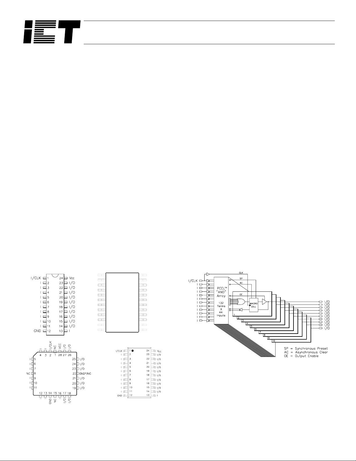
Figure 1. Pin Configuration Figure 2. Block Diagram
24
VCC
23
I/O
22
I/O
21
I/O
20
I/O
19
I/O
18
I/O
17
I/O
I/O
16
I/O
15
I/O
14
I
13
DIP
PLCC
*Optional extra ground pin for
-7/I-7 speed grade.
I/CLK
I
I
I
I
I
I
I
I
I
I
GND
TSSOP
1
2
3
4
5
6
7
8
9
10
11
12
SOIC
1 of 10
04-02-009F
Page 2
PEELTM 22CV10A
I/CLK
0
2
9
10
20
I
21
33
I
34
48
I
49
65
ASYNCHRONOUS CLEAR
(TO ALL MACROCELLS)
MACRO
CELL
MACRO
CELL
MACRO
CELL
MACRO
CELL
MACRO
CELL
I/O
I/O
I/O
I/O
I/O
I
66
82
I
83
97
I
98
110
I
111
121
I
124
130
I
131
I
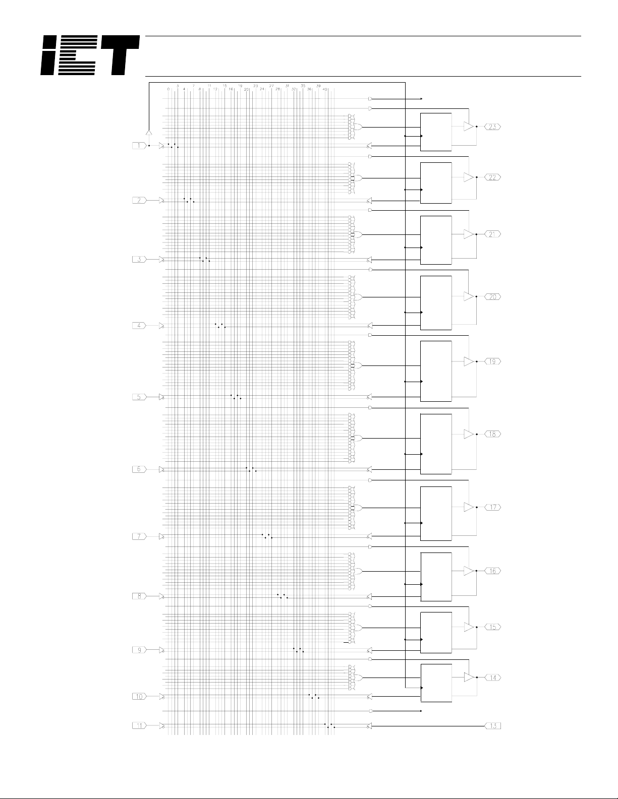
Figure 3. PEEL™22CV10A Logic Array Diagram
MACRO
CELL
MACRO
CELL
MACRO
CELL
MACRO
CELL
MACRO
CELL
SYNCHRONOUS PRESET
(TO ALL MACROCELLS)
I/O
I/O
I/O
I/O
I/O
I
2 of 10
04-02-009F
Page 3

PEELTM 22CV10A
Function Description
The PEEL™22CV10A imp lements logic functions as su mof-products expressions in a programmable-AND/ fixed-OR
logic array. User-defined functions are created by programming the connections of input si gnals into the array. Userconfigurable output structu res in the fo rm of I/O macroc ells
further increase logic flexibi lity.
Architecture Overview
The PEEL™22CV10A architecture is illustrated in the block
diagram of Figure 2. Twelve dedicated inputs and 10 I/Os
provide up to 22 inputs and 10 outp uts for cre ation of log ic
functions. At the core of the device is a programmable electrically-erasabl e AND array which drives a fixed OR ar ray.
With this structure, the PEEL™22CV10A can implement up
to 10 sum-of-products logic expressions.
Associated with each of the 10 OR functions is an I/O macrocell which can be indep endentl y progr ammed to on e of 4
different configurations. The programmable macrocells
allow each I/O to cre ate sequential or combinatorial logic
functions with either active-high or active-low polarity.
AND/OR Logic Array
The programmable AND array of the PEEL™22CV10A
(shown in Figure 3) is formed by input lines intersecting
product terms. Th e input lines a nd product te rms are use d
as follows:
programming selected connections in the AND array. (Note
that PEEL™ device programmers automatically program
the connections on u nused product term s so that they will
have no effect on the output function.)
Variable Product Term Distribution
The PEEL™22CV10A pro vides 120 produc t terms to drive
the 10 OR functions. The se product terms are distributed
among the outputs in groups of 8, 10, 12, 14 and 16 to form
logical sums (see Figure 3). This distribution allows optimum use of device re-sources.
Programmable I/O Macrocell
The output macrocell provides complete control over the
architecture of each output. The ability to configure each
output independently permi ts users to tailor the configuration of the PEEL™22CV 10A to the pr ec ise r eq uir em ent s o f
their designs.
Macrocell Architecture
Each I/O macroc ell, as s hown in Figure 4, consists of a Dtype flip-flop and two signal-select multiplexers. The configuration of each macrocell is determined by the two
EEPROM bits contr olling these mu ltiplexers (r efer to Table
1). These bits determine output polarity and output type
(registered or non-registered). Equivalent circuits for the
four macro-cell configurations are illustrated in Figure 5.
44 Input Lines:
24 input lines carry the true and complement
of the signals applied to the 12 input pins
20 additional lines carry the true and complement
values of feedback or input signals from
the 10 I/Os
132 product terms:
120 product terms (arranged in 2 groups of 8,
10, 12, 14 and 16) used to form logical sums
10 output enable terms (one for each I/O)
1 global synchronous present term
1 global asynchronous clear term
At each input-line/product-term intersection there is an
EEPROM memory cell which determines whether or not
there is a logical connection at that intersection. Each product term is essentiall y a 44- i npu t AND gate . A p roduc t te rm
which is connected to b oth the true and complem ent of an
input signal will al ways be FALSE, and thus will not affect
the OR function that i t drives. When al l the connec tions on
a product term are opened, a “don ’t care” state exists and
that term will always be TRUE. When programming the
PEEL™22CV10A, the device programmer first performs a
bulk erase to remove the previous pattern. The erase cycle
opens every logical co nnection in the array. The device is
then configured to perform the user-defined function by
Output Type
The signal from the OR array ca n be fed di re ct ly to the output pin (combinatorial function) or latched in the D-type flipflop (registered func tion). The D-type flip-flop la tches data
on the rising edge of the clock and is cont roll ed by the global preset and c lear terms. When th e synchronous prese t
term is satisfied, the Q output of the register will be set
HIGH at the next rising edg e of the clock input. Satis fying
the asynchronou s clear te rm will se t Q LOW, regardless o f
the clock state. If bo th terms are satisfied simult aneously,
the clear will override the preset.
Output Polarity
Each macrocell can be configured to implement active-high
or active-low logic. Programmable polarity eliminates the
need for external inverters.
Output Enable
The output of each I/O macrocell can be enabled or disabled under the control of its associated programmable
output enable product term. When the logical conditions
programmed on the output enable term are satisfied, the
output signal is propagated to the I/O pin. Otherwise, the
output buffer is driven into the high-impedance state.
Under the control of the output enable term, the I/O pin can
function as a dedicated inp ut, a dedicated output, or a bidirectional I/O. Opening every connection on the output
3 of 10
04-02-009F
Page 4

PEELTM 22CV10A
enable term will permanen tly enable the output buffer and
yield a dedicated outp ut. Co nverse ly, if every connection is
intact, the enable term will always be logically false and the
I/O will function as a dedicated input.
Input/Feedback Select
When configuring an I/O macrocell to implement a registered function (configur ations 1 and 2 in Figure 5), the Q
output of the flip-flo p drives th e feedback term . When configuring an I/O macrocell to implement a combinatorial
function (configurati ons 3 and 4 in Figur e 5), the feedback
signal is taken from the I/O pin. In this c as e, the pin ca n b e
used as a dedicated input or a bi-directional I/O. (Refer
also to Table 1.)
Additional Macro Cell Configurations
Besides the standard four-configuration macrocell shown in
Figure 5, each PEEL™22CV10A provides an additional
eight configurations that can be used to increase design
flexibility. The configurations are the same as provided by
the PEEL™18CV8 and PEEL™22CV10AZ. However, to
maintain JEDEC file compatibility with standard 22V10
PLDs the additional c onfigurations can only be utilized by
specifying the PEEL™22CV10A+ for logic assembly and
programming. To reference these additional con figurations
please refer to the PEEL™22CV 10A+ specificat ions at the
end of this data sheet.
Design Security
The PEEL™22CV1 0A provides a special EEP ROM security bit that prevents unauthorized reading or copying of
designs programmed into th e devic e. The s ec urity bit is se t
by the PLD programmer, either at the conclusion of the programming cycle or as a sepa rate step after the de vice has
been programmed. Onc e the secu rity bit is set, it is impo ssible to verify (read) or pr og ram the PEEL™ until the entir e
device has first been erased with the bulk-erase function.
Signature Word
The signature word fe ature allows a 24-bit cod e to be programmed into the PEEL™22CV10A if the
PEEL™22CV10A+ s oftware option is used. T he code can
be read back even after the sec urity bit has been set. Th e
signature word can be used to identify the pattern programmed into the device or to record the de sign revision,
etc.
Figure 4. Block Diagram of the PEEL™ 22CV10A I/O Macrocell.
4 of 10
04-02-009F
Page 5

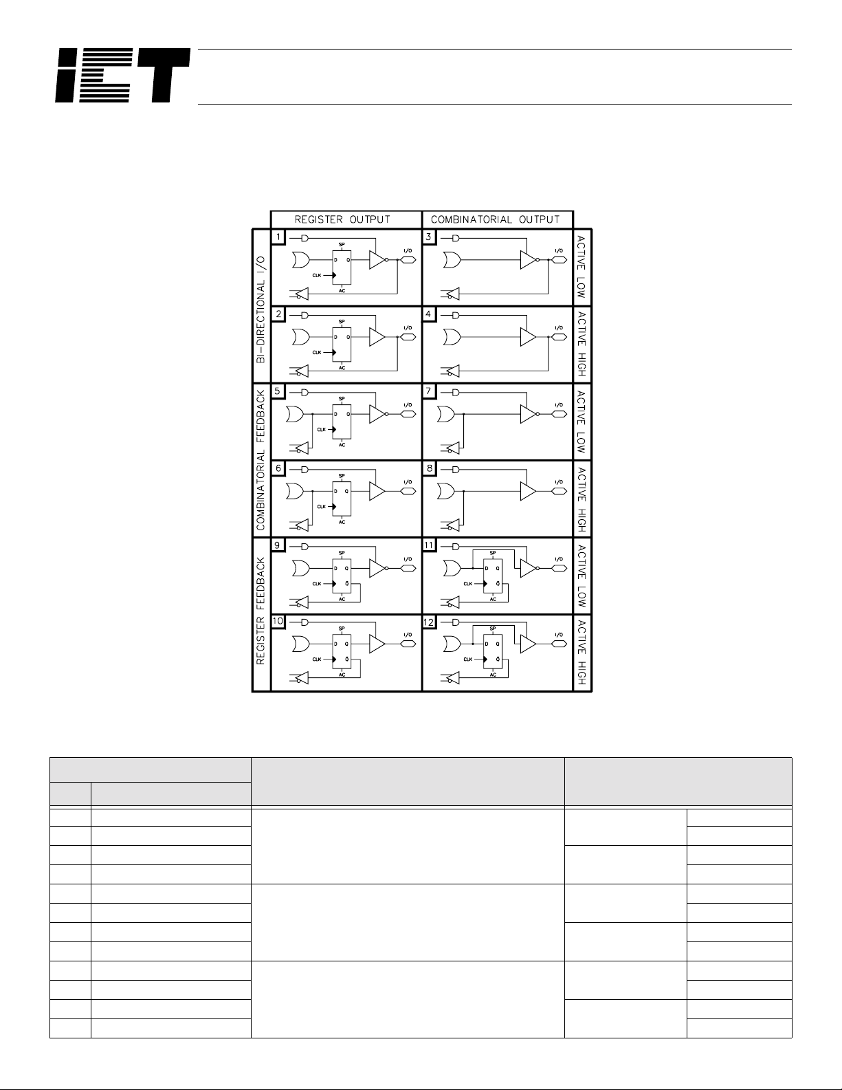
Figure 5. Four Configurations of the PEEL™22CV10A I/O Macrocell
PEELTM 22CV10A
Table 1. PEEL™ 22CV10A Macrocell Configuration Bits
Configuration
Input/Feedback Select Output Select
# A B
1 0 0
21 0 Active High
30 1
41 1 Active High
Register Feedback Register
Bi-Directional I/O Combinatorial
Active Low
Active Low
5 of 10
04-02-009F
Page 6
Additional Macrocell Configurations
Besides the standard four-configuration macrocells, each
PEEL™22CV10A provides an additional eight configurations (twelve total) that can be used to increase design flexibility
PEELTM 22CV10A
(see Figure 6 and Table 2). For logic assembly of all twelv e
configurations, sp ecify PEEL™2 2CV10A+ . Also, selec t the
PEEL™22CV10A+ for programming.
Figure 6. Twelve Configurations of the PEEL™22CV10A+ I/O Macrocell
Table 2. PEEL™ 22CV10A+ Macrocell Configuration Bits
Configuration
Input/Feedback Select Output Select
# A B C D
1 1 1 1 1
2 0 1 1 1 Active High
3 1 0 1 1
4 0 0 1 1 Active High
5 1 1 1 0
6 0 1 1 0 Active High
7 1 0 1 0
8 0 0 1 0 Active High
9 1 1 0 0
10 1 0 0 0 Active High
11 1 0 0 0
12 0 0 0 0 Active High
Bi-Directional I/O
Combinatorial Feedback
Register Feedback
Register
Combinatorial
Register
Combinatorial
Register
Combinatorial
6 of 10
Active Low
Active Low
Active Low
Active Low
Active Low
Active Low
04-02-009F
Page 7

PEELTM 22CV10A
operating conditions. Pr oper operation outside of these levels is not
guaranteed. Exposur e to absolute maximum ra tings may cause per-
This device has been designed and tested for the recommended
Table 6. Absolute Maximum Ratings
manent damage.
Symbol Parameter Conditions Ratings Unit
VCC Supply Voltage Relative to Ground -0.5 to + 7.0 V
V
I, VO
O
I
ST Storage Temperature -65 to + 150 °C
T
LT
T
Voltage Applied to Any Pin
Output Current Per pin (IOL, IOH)±25mA
Lead Temperature Soldering 10 seconds +300 °C
2
Relative to Ground
1
-0.5 to VCC + 0.6 V
Table 7. Operating Ranges
Symbol Parameter Conditions Min Max Unit
VCC Supply Voltage
T
A Ambient Temperature
R Clock Rise Time See Note 3 20 ns
T
T
F Clock Fall Time See Note 3 20 ns
RVCC
T
CC
V
Rise Time See Note 3 250 ms
Commercial 4.75 5.25
Industrial 4.5 5.5
Commercial 0 +70
Industrial -40 +85
V
°C
Table 8. D.C. Electrical Characteristics over the recommended operating conditions
Symbol Parameter Conditions Min Max Unit
VOH Output HIGH Voltage VCC = Min, IOH = -4.0mA 2.4 V
CC
13
13
)
VCC = Min, IOH = -10µA VCC - 0.3 V
CC
VCC = Min, IOH = -10µA 0.15 V
IN
= 0V or 3V
V
f = 25MHz
All outputs disabled
T
A = 25°C, VCC = 5.0V
@ f = 1 MHz
= Min, I
OL
= 16mA 0.5 V
CC
-7/I-7 90/100
-10/I-10 90/100
4
-15/I-15 135/145
-25/I-25 30/40
±10 µA
6pF
V
OHC
OL
V
OLC
V
IH
V
IL Input LOW Level -0.3 0.8 V
V
I
IL Input Leakage Current VCC = Max, VIN = GND ≤ VIN £ VCC ±10 µA
OZ
I
10
ICC
7
IN
C
7
COUT
Output HIGH Voltage - CMOS
Output LOW Voltage - TTL V
Output LOW Voltage - CMOS
Input HIGH Level 2.0 VCC + 0.3 V
Output Leakage Current I/O = High-Z, GND ≤ VO ≤ V
VCC Current
(See CR-1 for typical I
Input Capacitance
Output Capacitance 12 pF
mA
7 of 10
04-02-009F
Page 8

PEELTM 22CV10A
Table 9. A.C. Electrical Characteristics
Over the Operating Range
8,11
-7 / I-7 -10 / I-10 -15 / I-15 -25 / I-25
Symbol Parameter
PD
t
OE
t
t
OD
CO1
t
t
CO2
CF
t
t
SC
HC
t
CL, tCH
t
CP
t
MAX1
f
MAX2
f
MAX3
f
AW Asynchronous Reset Pulse Width 7.5 10 15 25 ns
t
AP
t
t
AR Asynch. Reset recovery time 7.5 10 15 25 ns
t
RESET
Input5 to non-registered output
tSC
6
6
+ tCF)
8
CO1
) 8.5 11 18 30 ns
12
12
12
Input5 to output enable
Input5 to output disable
Clock to Output 5.5 6 8 15 ns
Clock to comb. output delay via
internal registered feedback
Clock to Feedback 3.5 4 5 9 ns
Input5 or Feedback Setup to Clock
Input5 Hold After Clock
Clock Low Time, Click High Time
Min Clock Period Ext (tSC + t
Internal Feedback (1
External Feedback (1/tCP)
No Feedback (1/tCL + tCH)
Input5 to Asynchronous Reset
Power-on Reset Time for
registers in Clear State
Min Max Min Max Min Max Min Max
7.5 10 15 25 ns
7.5 10 15 25 ns
7.5 10 15 25 ns
10 12 17 35 ns
35815ns
0000ns
34613ns
142 111 76.9 41.6 MHz
117 90.9 62.5 33.3 MHz
166 125 83.3 38.4 MHz
7.5 10 15 25 ns
5555µs
Unit
Switching Waveforms
Registered Feedback,
Synchronous Preset
Notes
1. Minimum DC input is -0.5V, however inputs may undershoot to -2.0V for
periods less than 20ns.
I
2. V
and VO are not specified for program/verify operation.
3. Test points for Clock and V
levels.
4. I/O pins are 0V and 3V.
5. “Input” refers to an Input pin signal.
OE
6. t
is measured from input transition to V
from input transition to V
in Section 5 of the Data Book.
7. Capacitances are tested on a sample basis.
Inputs, I/O,
Clock
Asynchronous
Reset
Registered
Outputs
Combinatorial
Outputs
CC
in tR, tF are referenced at 10% and 90%
OH
-0.1V or V
OL
+0.1V; V
REF
± 0.1V, t
REF =VL
OD
is measured
see test loads
8. Test conditions assume: signal transition times of 3ns or less from the
10% and 90% points, timing reference levels of 1.5V (unless otherwise
specified).
9. Test one output at a time for a duration of less than 1sec.
10. ICC for a typical application: This parameter is tested with the device
programmed as an 8-bit Counter.
11. PEEL™ Device test loads are specified in Section 6 of this Data Book.
12. Parameters are not 100% tested. Specifications are based on initial
characterization and are tested after any design or process modification which may affect operational frequency.
13. Available only for 22CV10A -15/I-15/-25/I-25 grades.
8 of 10
04-02-009F
Page 9

PEELTM 22CV10A
Table 6. Ordering Information
Part Number Speed Temperature Package
PEEL22CV10AP-7
PEEL22CV10API-7 I
PEEL 22CV10AJ-7
PEEL 22CV10AJI-7 I
PEEL 22CV10AS-7
PEEL 22CV10ASI-7 I
PEEL 22CV10AT-7
PEEL 22CV10ATI-7 I
PEEL 22CV10AP-10
PEEL 22CV10API-10 I
PEEL 22CV10AJ-10
PEEL 22CV10AJI-10 I
PEEL 22CV10AS-10
PEEL 22CV10ASI-10 I
PEEL 22CV10AT-10
PEEL 22CV10ATI-10 I
PEEL 22CV10AP-15
PEEL 22CV10API-15 I
PEEL 22CV10AJ-15
PEEL 22CV10AJI-15 I
PEEL 22CV10AS-15
PEEL 22CV10ASI-15 I
PEEL 22CV10AT-15
PEEL 22CV10ATI-15 I
PEEL 22CV10AP-25
PEEL 22CV10API-25 I
PEEL 22CV10AT-25
PEEL 22CV10ATI-25 I
PEEL 22CV10AJ-25
PEEL 22CV10AJI-25 I
PEEL 22CV10AS-25
PEEL 22CV10ASI-25 I
7.5ns
7.5ns
7.5ns
7.5ns
10ns
10ns
10ns
10ns
15ns
15ns
15ns
15ns
25ns
25ns
25ns
25ns
C
C
C
C
C
C
C
C
C
C
C
C
C
C
C
C
P24
J28
S24
T24
P24
J28
S24
T24
P24
J28
S24
T24
P24
T24
J28
S24
9 of 10
04-02-009F
Page 10

PEELTM 22CV10A
Part Number
PEEL™ 22CV10A PI-25
Package
P = Plastic 300mil DIP
J = Plastic (J) Leaded Chip Carrier (PLCC)
S = SOIC
T = TSSOP
Device
Suffix
Speed
-7 = 7.5ns tpd
-10 = 10ns tpd
-15 = 15ns tpd
-25 = 25ns tpd
Temperature Range and Power Options
(Blank) = Commercial 0 to 70°C
I = Industrial -40 to +85°C
10 of 10
04-02-009F
 Loading...