

Page 1
PRELIMINARY
PD43__06
Powerex, Inc., Hillis Street, Youngwood, Pennsy l vania 15697 (724) 925-7272
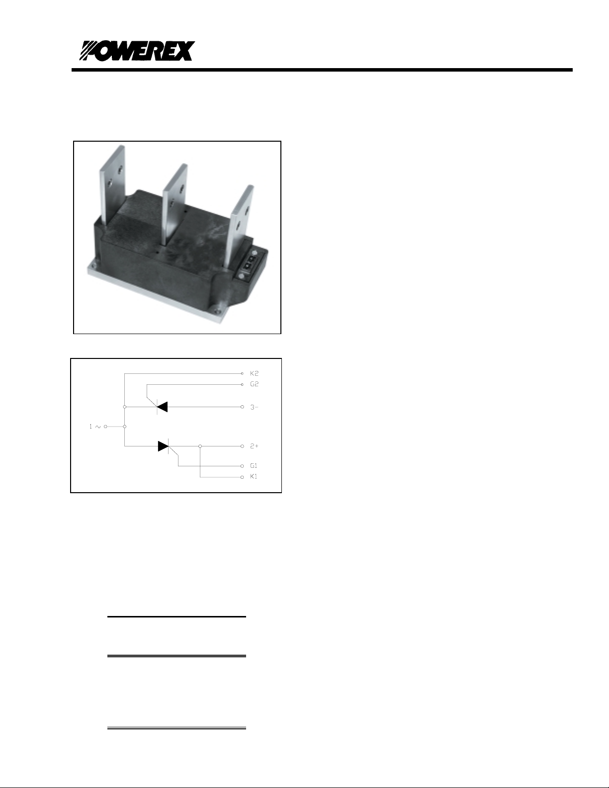
Dual SCR Isolated Module
POW-R-BLOK
TM
600 Amperes / Up to 2400 Volts
Ordering Information
Select the complete eight-digit
module part number from the table
below.
Example: PD432406 is a 2400 Volt,
600A Average Dual SCR Isolated
POW-R-BLOK
TM
Module
Type
PD43
Voltage
Volts (x100)
20
22
24
:
Current
Amperes
(x100)
06
Description:
Powerex Dual SCR Modules are
designed for use in applications
requiring phase control and isolated
packaging. The modules are isolated
for easy mounting with other
components on a common heatsink.
Features:
T Electrically Isolated Heatsinking
T Compression Bonded Elements
T Metal Baseplate
T Low Thermal Impedance
for Improved Current Capability
Benefits:
T No Additional Insulation
Components Required
T Easy Installation
T No Clamping Components
Required
T Reduce Engineering Time
Applications:
T Bridge Circuits
T AC & DC Motor Drives
T Motor Soft Starters
T Battery Supplies
T Power Supplies
T Large IGBT Circuit Front Ends
10/04/2002
Page 2

PRELIMINARY
Powerex, Inc., Hillis Street, Youngwood, Pennsy l vania 15697 (724) 925-7272
POW-R-BLOK
Dual SCR Isolated Module
600 Amperes / Up to 2400 Volts
PD43__06
TM
Absolute Maximum Ratings
Characteristics Conditions Symbol Units
Repetitive Peak Forward and Reverse Blocki ng
Voltage
Non-Repetitive Peak Block i ng Voltage
(t < 5 msec)
RMS Current AC Switch Configuration
o
(180
Conduction)
180° Conduction, T
180° Conduction, T
180° Conduction, T
180
Conduction, T
°°°°
180° Conduction, T
180° Conduction, T
RMS Current Per SCR
o
(180
Conduction)
180° Conduction, T
180° Conduction, T
180° Conduction, T
180
Conduction, T
°°°°
180° Conduction, T
180° Conduction, T
Average Forward Current Per SCR
o
(180
Conduction)
180° Conduction, T
180° Conduction, T
180° Conduction, T
180
Conduction, T
°°°°
180° Conduction, T
180° Conduction, T
Peak One Cycle Surge Current, Non-Repeti t ive
Tj = 25C, Vr = 0
Peak One Cycle Surge Current, Non-Repeti t ive
Tj = 25C, Vr = Vrrm
Peak One Cycle Surge Current, Non-Repeti t ive
Tj = 125C, Vr = 0
Peak One Cycle Surge Current, Non-Repeti t ive
Tj = 125C, Vr = Vrrm
Peak Three Cycle Surge Current, Non-Repetitive 60 Hz, Tj = 125C, Vr = Vrrm I
Peak Ten Cycle Surge Current, Non-Repetitive 60 Hz, Tj = 125C, Vr = Vrrm I
I2t for Fusing for One Cycle
Tj = 125C, Vr = Vrrm
Maximum Rate-of-Rise of On-State Current,
Per JEDEC Standard 397 5.2.2. 6 di/dt 400 A/µs
(Non-Repetitive)
Maximum Rate-of-Rise of On-State Current,
Per JEDEC Standard 397 5.2.2. 6 di/dt 150 A/µs
(Repetitive)
Operating Temperature TJ -40 to +125 °C
Storage Temperature T
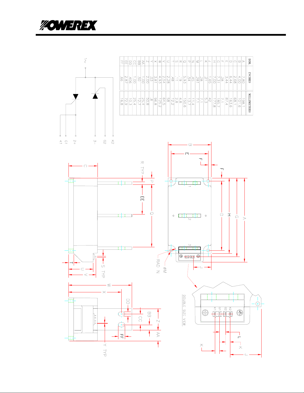
Max. Mounting Torque, M6 Mounting Screw 132
Max. Mounting Torque, M10 Terminal Screw 106
Module Weight, Typic al 455 g
11.75 lb
V Isolation @ 25C
10/04/2002
V
V
=66°C
C
=71°C
C
=76°C
C
=81
C
C
°°°°
=86°C
C
=90°C
C
=66°C
C
=71°C
C
=76°C
C
=81
C
C
°°°°
=86°C
C
=90°C
C
=66°C
C
=71°C
C
=76°C
C
=81
C
C
°°°°
=86°C
C
=90°C
C
60 Hz
50 Hz
60 Hz
50 Hz
60 Hz
50 Hz
60 Hz
50 Hz
8.3 milliseconds
10 milliseconds
& V
DRM
RRM
V
RSM
I
T(RMS)
I
T(RMS)
I
T(RMS)
I
T(RMS)
I
T(RMS)
I
T(RMS)
I
T(RMS)
I
T(RMS)
I
T(RMS)
I
T(RMS)
I
T(RMS)
I
T(RMS)
I
T(AV)
I
T(AV)
I
T(AV)
I
T(AV)
I
T(AV)
I
T(AV)
I
TSM
I
TSM
I
TSM
I
TSM
I
TSM
I
TSM
I
TSM
I
TSM
23,690 A
TSM
18,615 A
TSM
I2t
2
I
t
-40 to +150 °C
stg
V
rms
Up to 2400 V
+ 100V V
RRM
1665
1550
1440
1330
1220
1110
1178
1100
1020
942
864
785
750
700
650
600
550
500
50,890
46,400
33,925
30,935
44,250
40,350
29,500
26,900
3.63 x 10
3.62 x 10
6
6
2
A
2
A
in. – Lb.
15
Nm
in. – Lb.
12
Nm
3000 V
A
A
A
A
A
A
A
A
A
A
A
A
A
A
A
A
A
A
A
A
A
A
A
A
A
A
sec
sec
Page 3

PRELIMINARY
Powerex, Inc., Hillis Street, Youngwood, Pennsy l vania 15697 (724) 925-7272
POW-R-BLOKTM
Dual SCR Isolated Module
600 Amperes / Up to 2400 Volts
PD43__06
Electrical Characteristics, TJ=25
Characteristics Symbol Test Conditions Min. Max.
C unless otherwise specified
°°°°
Units
Repetitive Peak Forward Leakage Current I
Repetitive Peak Reverse Leakage Current I
Peak On-State Voltage VTM I
Threshold Voltage, Low-level
Slope Resistance, Low-level
Threshold Voltage, High-level
Slope Resistance, Hi gh-l evel
VTM Coefficients, Full Range
Up to 2400V, TJ=125°C 100 mA
DRM
Up to 2400V, TJ=125°C 100 mA
RRM
=3000A, TJ=125°C 1.75 V
TM
V
V
(TO)1
r
T1
(TO)2
r
T2
= 125°C, I = 15%I
T
J
= 125°C, I = πI
T
J
T(AV)
T(AV)
TJ = 125°C, I = 50A to 6kA
V
= A+ B Ln I +C I + D Sqrt I
TM
to πI
0.869
T(AV)
0.237 V mΩ
to I
1.055
TSM
0.175 V mΩ
A =
B =
C =
D =
0.93159
-4.51 E-02
9.95 E-05
1.29 E-02
Minimum dV/dt dV/dt Exponential to 0.67V
T
=125°C, Gate Open
j
Gate Trigger Current IGT T
Gate Trigger Voltage VGT T
Non-Triggering Gate Voltage V
T
GDM
=25°C, VD=12V 200 mA
j
=25°C, VD=12V 3.0 Volts
j
=125°C, VD= ½ V
j
DRM
0.15 Volts
DRM
600 V/µs
Holding Current IH 300 mA
Peak Forward Gate Current I
Peak Reverse Gate Voltage V
Maximum Average Gate Power Dissipation P
4.0 Amp
GTM
5 Volts
GRM
16 Watts
GM (AVE)
Thermal Characteristics
Characteristics Symbol
Thermal Resistance, Junction to Case
Thermal Impedance Coeff i cients
R
Θ
J-C
Z
Θ
J-C
Per Module, both conducting
Per Junction, both conducting
Z
Θ
J-C
+ K
+ K
+ K
Thermal Resistance, Case to Sink Lubricated
R
Θ
C-S
= K1 (1-exp(-t/
(1-exp(-t/
2
(1-exp(-t/
3
(1-exp(-t/
4
))
1
t
))
2
t
))
3
t
))
4
t
= 5.04 E-04
K
1
K2 = 2.31 E-03
K3 = 2.83 E-03
K4 =5.24 E-02
Per Module 0.009
10/04/2002
Max. Units
0.029
0.058
= 2.47 E-03
1
t
= 4.42 E-02
2
t
= 1.370
3
t
= 9.668
4
t
C/W
°
C/W
°
C/W
°
Page 4
PRELIMINARY
PD43__06
Powerex, Inc., Hillis Street, Youngwood, Pennsy l vania 15697 (724) 925-7272
600 Amperes / Up to 2400 Volts
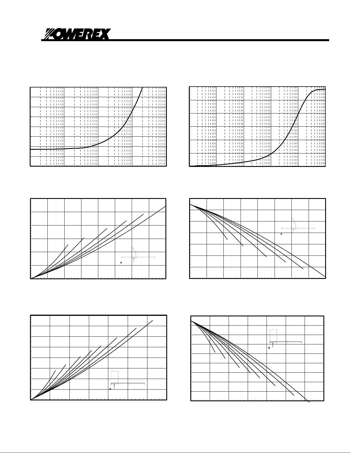
Typical On-State Forward Voltage Drop
4
(Tj = 125C)
0.06
Dual SCR Module
Maximum Transient Thermal Impedance
(Junction To Case)
3.5
3
2.5
2
1.5
1
On-State Voltage - Vt - Volts
0.5
0
10 100 1000 10000 100000
1200
1000
800
600
400
200
Max. Power Dissipation Per SCR - Watts_
0
0 100 200 300 400 500 600 700 800
1600
1400
1200
1000
800
600
400
Max. Power Dissipation Per SCR - Watts_
200
0
0 200 400 600 800 1000 1200 1400
Instantaneous On-State Current - It - Amperes
Maximum On-State Power Dissipation
(Sinusoidal Waveform)
90°
60°
30°
15°
180
0
CONDUCTION ANGLE
Average On-State Current - It(av) - Amperes
Maximum On-State Power Dissipation
(Rectangular Waveform)
270°
180°
120°
90°
60°
30°
15°
180
0
CONDUCTION ANGLE
Average On-State Current - It(av) - Amperes
360°
360
10/04/2002
120°
0.05
0.04
0.03
0.02
Thermal Impedance - R jc - °C/W
0.01
0.00
0.001 0.01 0.1 1 10 100
Maximum Allowable Case Temperature
Time - t - Seconds
(Sinusoidal Waveform)
130
180°
360
120
110
180
100
90
80
Max. Case Temperature - Tcase -°C_
70
60
0 100 200 300 400 500 600 700 800
15°
30°
60°
0
CONDUCTION ANGLE
90°
120°
360
180°
Average On-State Current - It(av) - Amperes
Maximum Allowable Case Temperature
(Rectangular Waveform)
130
120
110
100
90
80
70
60
Max. Case Temperature - Tcase -°C_
50
15°
30°
60°
90°
120°
180
0
CONDUCTION ANGLE
180°
270°
360
360°
40
0 200 400 600 800 1000 1200 1400
Average On-State Current - It(av) - Amperes
Page 5
PRELIMINARY
PD43__06
Powerex, Inc., Hillis Street, Youngwood, Pennsy l vania 15697 (724) 925-7272
600 Amperes / Up to 2400 Volts
Dual SCR Module
10/04/2002
 Loading...