

Page 1
Advance information
PBL 40310
PBL 403 10
March 2001
PBL 403 10
3.5 V GSM 900 MHz Power Amplifier
Description.
The PBL 40310 is a highly integrated single-ended silicon MMIC power amplifier
intended for use in GSM terminals. It delivers 35 dBm at 900 MHz with 55 % power added
efficiency into a 50 Ω unbalanced load using a single 3.5 V supply.
The circuit has an analog ramp signal to control output power level and a logical on/
off signal for power down mode. It can be used in dual-band amplifiers using the band
select logical signal. It can be operated up to 50 % duty cycle with minimum performance
degradation. The circuit is housed in a specially designed QSOP16 (150 mil body)
package and the implementation requires only few external components.
25 GHz ft state-of-the-art deep trench isolated double-poly silicon bipolar process
with additional features for improved wireless performance has been used. On-chip
capacitors and inductors are used for the integrated internal matching network. Special
front-side metallized substrate contacts provide excellent ground paths from active
devices to the highly doped semiconductor substrate and package ground.
V
CC
Key features.
• 2.7 to 5.0 V single supply operation
• 35 dBm output power at 3.5 V
• 55 % Power Added Efficiency
• Input matched to 50 Ω
• Complete on chip input and
interstage matching
• Analog power control
• Less than 10 µA current
consumption in power down mode
• Proven RF Silicon Technology
Reliability
• Minimum number of external
components for low overall solution
cost
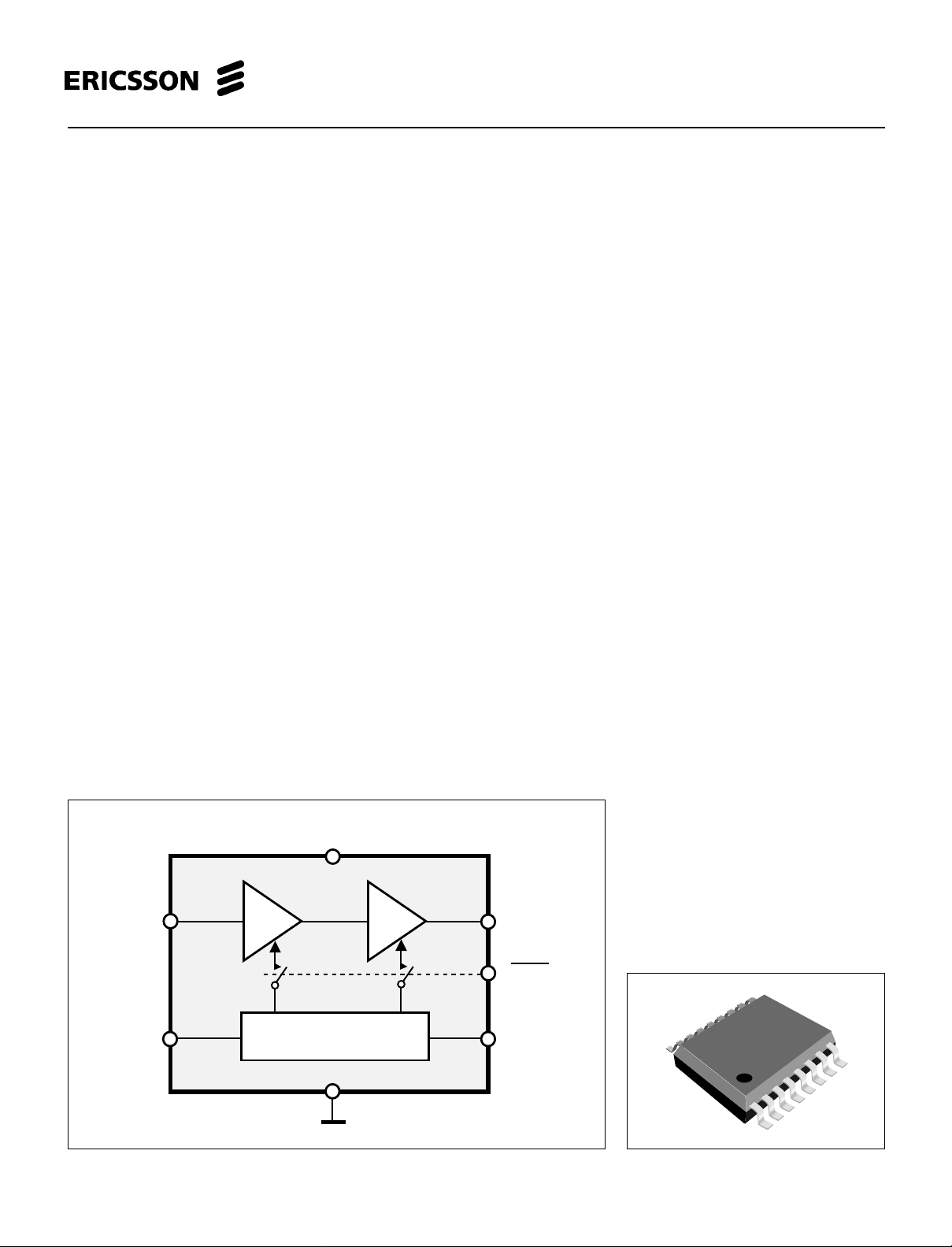
RFin
Power
Control
Figure 1. Block diagram.
BIAS
RFout
B
SEL
TX - ON
Figure 2. Package outlook.
1
Page 2

PBL 403 10
Maximum Ratings
Parameter Conditions Symbol Min. T yp. Max. Unit
Supply voltage, continuous V
Power control voltage V
Input power P
Operating Case Temperature T
Storage Temperature Range T
CC
APC
IN
OP
STORAGE
DC Electrical Characteristics
VCC = 3.5 V, TA= + 25°C unless otherwise stated.
Parameter Conditions Symbol Min. T yp. Max. Unit
Supply voltage range V
Supply current V
Standby supply current V
Power down leakage current V
Input current, V
APC
= 2.5 V, no RF signal applied I
APC
<=0.5 V , TX-ON=HIGH I
APC
<= 0.5 V , TX-ON=LOW I
APC
0 < V
< 3.5 V 2.0 3.0 mA
APC
CC
CC
STBY
LEAK
-0.5 6.0 V
-0.5 6.0 V
+20 dBm
-40 +85 °C
-30 +100 °C
2.7 5.0 V
150 mA
3.0 mA
5.0 µA
AC Electrical Characteristics
VCC = 3.5 V, f
pulse width = 577 µs, T
Parameter Conditions Symbol Min. T yp. Max. Unit
Frequency range f
Input impedance Z
Input VSWR P
Recommended input power P
Power gain P
Output power P
Power added efficiency η 50 55 %
Output power V
nd
2
harmonic 2 fo tbd dBc
rd
3
harmonic 3 fo tbd dBc
Output Noise RBW=100 kHz, f=925 to 935 MHz tbd dBm
Output Noise RBW=100 kHz, f=925 to 960 MHz tbd dBm
Forward isolation V
Stability, load VSWR All phases, no oscillations. VSWR 6:1
Ruggedness, load VSWR All phases, no damage. VSWR 10:1
Power control for max. P
Power control for min. P
Power control slope -10 dBm < P
= 900 MHz, P
IN
= 8 dBm, V
IN
= +25°C unless otherwise stated. All data measured on evaluation board.
A
OUT
OUT POUT
= 2.5 V, TX-ON = high (VCC), BSEL = low (GND), duty cycle = 12.5 %,
APC
IN
IN
= -10 to +20 dBm VSWR 2:1
IN
IN
= 0 dBm G
IN
= 2.9 V P
CC
< 0.5 V, PIN = -10 to + 10 dBm -25 dB
APC
< -30 dBm V
< 35 dBm tbd tbd dB/V
OUT
P
OUT
OUT
V
APC
APC
880 915 MHz
8.0 12.0 dBm
30 31 dB
34.5 35 dBm
2.5 V
50 Ω
33 dBm
0.5 V
This document contains advance information of a new product. Data given in this document shall be considered as preliminary
and may be changed without notice.
2
Page 3

PBL 403 10
(
)
Vcc
Vcc
GND
RFin
GND
TX-ON
SEL
B
V
APC
1
2
3
4
5
6
7
8
16
15
14
13
12
11
10
9
GND
GND
GND
RFout
RFout
GND
GND
GND
Figure 3. Pin configuration.
Pin Descriptions:
Refer to pin configuration.
SO Name Function SO Name Function
1 Vcc Supply voltage 9 GND Common ground
2 Vcc Supply voltage 10 GND Common ground
3 GND Common ground 11 GND Common ground
4 RFin RF input 12 RFout RF output
5 GND Common ground 13 RFout RF output
6 TX-ON Transmit ON 14 GND Common ground
7B
8VAPC Power control voltage 16 GND Common ground
SEL Band select 15 GND Common ground
40
35
30
25
20
15
10
Pout [dBm], Gain (dB)
5
Output power (dBm)
Gain (dB)
Effic i ency (%)
0
-10 -5 0 5 10 15
Figure 4. RF performance.
Pin
dBm
80
70
60
50
40
30
20
10
0
Eff (%)
RFin
Power
Control
4
8
12
BIAS
12
13
7
6
Common ground
B
SEL
TX-ON
Figure 5. Evaluation setup including network for unbalanced
input/output.
V
CC
RFout
3
Page 4

PBL 403 10
Package drawing, QSOP 16
min. max. min. max.
Dim.
A
1.35 0.532
A1
D
e
HE
Pin no 1
A
A1
B
C
L
0.10
B
0.21
C
0.19 0.25 0.0075 0.0098
D
9.80 9.98 0.386 0.393
E
3.81 0.150
e
0.635mm 0.025 inch ref.
5.70 6.20 0.2284 0.2240
H
L
0.41
α = 0−8 deg.
45 deg.
1.75 0.688
0.25
0.31 0.008 0.012
3.99 0.157
1.27 0.016 0.050
inchesmillimeters
0.004
0.0098
α
Note: This package has been chosen as a preliminary package. It will possibly be changed to a smaller solution.
This document contains advance information of a new product. Data given in this document shall be considered as preliminary
and may bechanged without notice.
Information given in this data sheet is believed to be accurate and reliable. However no responsibility is assumed
for the consequences of its use nor for any infringement of patents or other rights of third parties which may result
from its use. No license is granted by implication or otherwise under any patent or patent rights of Ericsson
Microelectronics AB. These products are sold only according to Ericsson Microelectronics AB's general conditions
of sale, unless otherwise confirmed in writing.
Specifications subject to change without
notice.
1522-PBL 403 10 Uen Rev.A
© Ericsson Microelectronics AB
March 2001
Ericsson Microelectronics AB
S-164 81 Kista-Stockholm, Sweden
Telephone: (08) 757 50 00
www.ericsson.se/microe
4
 Loading...