

Page 1

PBL 403 09
Preliminary
August 2000
PBL 403 09
3.6 V Differential Power Amplifier
for DECT Telecommunications system
Description.
The PBL 403 09 is a differential two stage silicon MMIC power amplifier intended for
use in handheld cordless terminals in the 1900 MHz band. It can deliver more than 27
dBm at 1900 MHz into a balanced 50 Ω load using a single 3.6 V supply. The circuit has
a logic input to control transmit on/off and can be operated up to 100 % duty cycle with
minimum performance degradation. The circuit is housed in a specially designed
QSOP16 (150 mil body ) package and the implementation requires only few external
components.
25 GHz ft state-of-the-art deep trench isolated double-poly silicon bipolar process
with additional features for improved wireless performance has been used. On-chip
capacitors and inductors are used for the integrated internal matching network. Special
front-side metallized substrate contacts provide excellent ground paths from active
devices to the highly doped semiconductor substrate and package ground.
V
CC
RF In A
RF Out A & V
CC
Key features.
• 27 dBm output power
• 25 dB small signal gain
• 50 % Power Added Efficiency
• Simple logic on/off power control
• Battery charging conditions to 5.0 V
• ESD protected
• Excellent ruggedness
• On-chip input and interstage
matching
• Differential input matched to 50 Ω
• Easy implementation with a simple
output matching network
• Proven RF Silicon Technology
Reliability
RF In B
Figure 1. Block diagram.
Power Control
PA-ON
RF Out B & V
CC
• Low overall solution cost
Applications.
• DECT
PBL 403 09
Figure 2. Package outlook.
1
Page 2
PBL 403 09
40
42
44
46
48
50
52
54
22.533.54
Vcc [V]
Pout [dBm]
Pin = 10 dBm
Pin = 4 dBm
Maximum Ratings
Parameter Symbol Min. Max. Unit
Supply voltage, continuous Vcc - 5.2 V
All inputs (zener protection) 6.5 V
Operating case temperature T
Storage temperature range T
op
Stg
Electrical Characteristics at room temperature
Unless otherwise stated the values below are valid for Vcc = 3.6 V, Pin = 4dBm, ZL = 50 Ω and f = 1900 MHz, pulsed mode
t = 417 µs, duty cycle 1/24. All data as measured in the recommended typical application circuit.
Parameter Condition Symbol Min. Typ. Max. Unit
Frequency range f 1880 1930 MHz
Power output PA - ON = low P 27 29 - dBm
Power Added Efficiency P
Power Added Efficiency P
Small signal Gain P
Isolation PA - ON = high, P
and 3
rd
harmonics PA - ON = low, Pin < 4 dBm -35 dBc
nd
2
Input VSWR 1.6:1 3:1
Load Mismatch P
Stability and spurious P
Supply current No input signal present, I
Supply current P
Supply current PA - ON = high I
Rise time P
Fall time P
PA - ON = low -0.5 0.5 V
PA - ON = high Vcc -0.5 Vcc +0.5 V
I ( PA - ON ) low 110 130 µA
in = 10 dBm PAE 45 50 - %
in = 4 dBm PAE 35 43 - %
in = -10 dBm G 25.5 - dB
in = 4 dBm -35 -30 dB
in = 4-10 dBm, Vcc = 5.2 V, no damage for 10 sec.
Load VSWR = 6:1 all phases
in = 4-10 dBm, Vcc = 3.0-5.2 V, All spurious below - 36 dBm
Load VSWR = 5:1 all phases
PA - ON = low
in = 4 dBm IDC 550 mA
out to 1dB from final value. tr 1 µA
Measure time from switch to low.
out to less than -20 dB measured tf 2 µs
from PA - ON pulse switched to high
-25 +80 °C
-30 +100 °C
DC 135 mA
DC 110µA
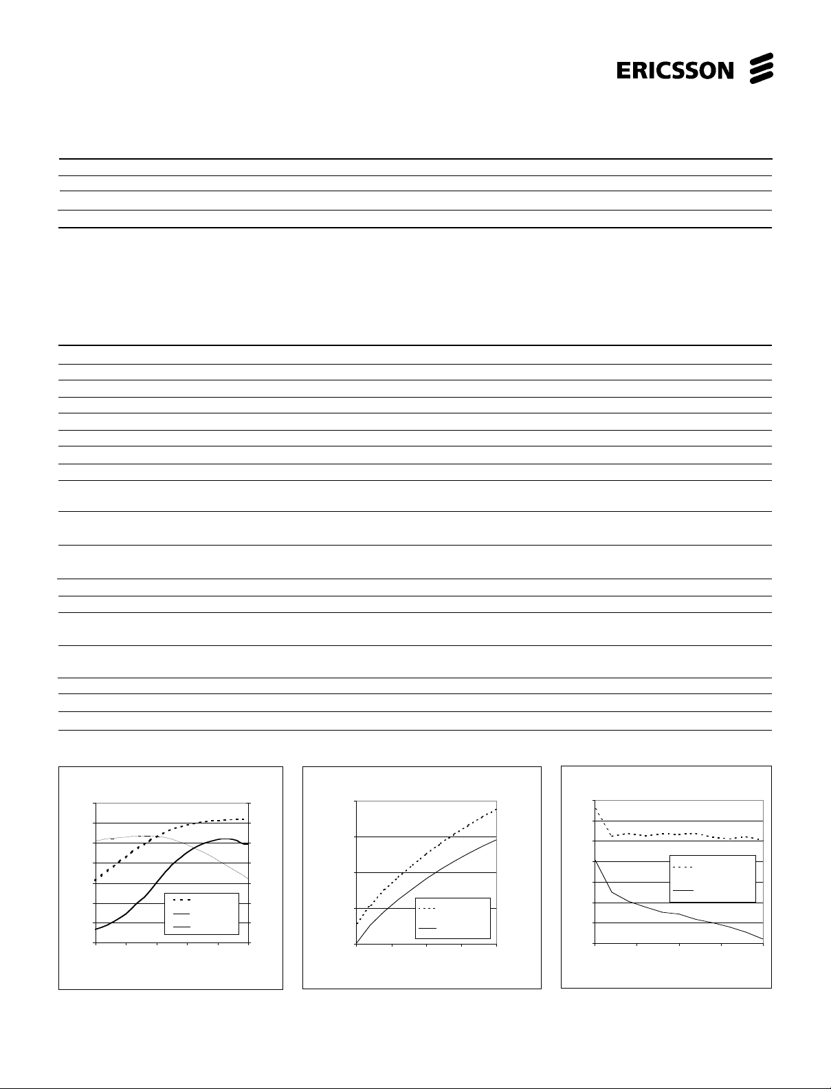
35
30
25
20
15
10
Pout [dBm]or Gain [dB]
5
0
-10 -5 0 5 10 15
Figure 3. P
Pin [dBm]
out
, Gain and PAE vs. P
Vcc = 3.6 V
2
Pout [dBm]
Gain [dB]
PAE [%]
70
60
50
40
30
PAE [%]
20
10
0
in
32
30
28
Pout [dBm]
26
24
2 2.5 3 3.5 4
Figure 4. P
and 10 dBm
Pin = 10 dBm
Pin = 4 dBm
Vcc [V]
out
vs. Vcc for Pin = 4 dBm
Figure 5. PAE vs.Vcc for Pin = 4 dBm
and 10 dBm
Page 3

PBL 403 09
Figure 6. Pin configuration.
PA-ON
GND
RFinA
GND
GND
RFinB
GND
Vcc
1
2
3
4
5
6
7
8
16
15
14
13
12
11
10
9
GND
GND
RFoutA
GND
GND
RFoutB
GND
GND
Pin Descriptions:
Refer to pin configuration.
SO Name Function SO Name Function
1 PA-ON PA On/Off Control pin (active low) 9 GND Common ground
2 GND Common ground 10 GND Common ground
3 RFinA
4 GND Common ground 12 GND Common ground
5 GND Common ground 13 GND Common ground
6 RFinB RF input 14 RFoutA RF output
7 GND Common ground 15 GND Common ground
8 Vcc Supply voltage 16 GND Common ground
RF input 11 RFoutB RF output
Functional description.
PBL403 09 is a differential two stage integrated power amplifier intended for DECT. The circuit is manufactured in a bipolar 5.0 V
technology with additional features for improved wireless performance. Input and interstage matching is done completely on-chip,
tuned to 1.9 GHz, and only normal supply decoupling plus output matching is necessary. If the device is used in a single ended
environment, input and output transformers need to be added to the external circuitry.
PBL403 09 is optimized to work at a supply voltage of 3.6 V, but is able to operate between 2.7 and 5.2 V. At 3.6 V it can deliver up
to 31 dBm when driven into compression, while 27 dBm is guaranteed with an input power of 4 dBm. Best Power Added Efficiency
(PAE) is obtained close to maximum output power where PAE exeeds 50 %. Small signal gain is 25-26 dB. In a DECT handset with
the duty cycle 1/24, the average power dissipation in the circuit is low, normally between 30 to 40 mW. In the base station, the duty
cycle can increase and PBL403 09 can be operated at CW with a small penalty in power gain and output power (< 0.5 dB).
Operation is controlled through a power-on pin which is active low. When active, the current consumption is typically 135 mA without
any input signal present. When not active, current consumption is less than 10 µA.
3
Page 4

PBL 403 09
Application information.
DECT SINGLE ENDED POWER AMPLIFIER
When used as a single ended power amplifier, please refer to fig.7 and the test board fig. 8.
The 50 Ω source impedance is converted to 50 Ω differential with an LC-CL structure. Two series capacitors AC-couples the signal
to the input of PBL403 09. Suitable value of the capacitors is 1 to 5 pF in order to compensate for series inductance of the PCB and
package. Input impedance of the PBL403 09 is 50 Ω differential.
The ideal collector load of the open collector RF output of PBL403 09 is about 11 Ω per side. A matching and combination network to
50 Ω single ended case is shown in fig. 7. A shunt capacitor (2.7 pF) transforms each output to 50 Ω. Both 50 Ω outputs are AC coupled
and then combined with an LC-CL structure to a 50 Ω single ended output.
PA-ON
Vcc
input
3.9n
1.5p
10n
1.5p
1.5p
PBL 403 09
1.5p
3.9n
GND
100p 100p
2.7p
Figure 7. Evaluation setup including networks for unbalanced input/output.
68
68
n
n
33p
33p
2.7p
1.1p
5.6n
output
1.1p
5.6n
Figure 8. Evaluation testboard.
4
Page 5

PBL 403 09
DECT RADIO WITH PBL402 15 TRANSCEIVER
PBL403 09 together with the transceiver chip PBL402 15 form the base of the radio platform for DECT systems. The transmission
part of the chip PBL402 15 has a differential output which can deliver up to 7 dBm. The output power can be programmed in steps.
The outputs are of open-collector type. Suitable network between PBL402 15 and PBL403 09 is therefore shunt inductors from the
open-collectors to Vcc and series capacitors to the RF inputs of PBL403 09. Suitable value of the capacitors is 1 to 5 pF in order to
compensate for the series inductance of the PCB and package. Input impedance of the PBL403 09 is 50 Ω differential.
The ideal collector load of the open collector RF output of PBL403 09 is about 11 Ω per side. A matching and combination network to
50 Ω single ended case is shown in fig.9. A shunt capacitor (2.7 pF) transforms each output to 50 Ω. Both 50 Ω outputs are AC coupled
and then combined with an LC-CL structure to a 50 Ω single ended output.
A power control signal with active low is received from PBL402 15. This signal controls power up/down of the PBL403 09.
Supply decoupling consists of high frequency and low frequency decoupling capacitors. The high frequency decoupling capacitor
should be placed close to the Vcc pin.
PA-ON
25
Vcc
41
PBL 402 15
38
39
TxTx+
3.9n
3.9n
Figure 9. DECT radio with PBL402 015 transceiver and PA.
1.5p
1.5p
33p
3
6
10n
8
1
PBL 403 09
GND
100p 100p
68
68
n
n
14
11
2.7p
2.7p
33p
33p
1.1p
5.6n
output
1.1p
5.6n
5
Page 6

PBL 403 09
Package drawing, QSOP 16
min. max. min. max.
Dim.
A
1.35 0.532
A1
D
e
HE
Pin no 1
A
A1
B
C
L
0.10
B
0.20 0.008
C
0.15 0.25 0.006 0.01
D
4.80 4.98 0.189 0.i96
E
3.81 0.150
e
0.635mm 0.025 inch ref.
5.70 6.20 0.228 0.244
H
L
0.40
α = 0−8 deg.
0.22 0.49 0.009 0.019
h
45 deg.
1.75 0.688
0.25
0.30 0.012
3.99 0.157
1.27 0.016 0.050
inchesmillimeters
0.004
0.0098
α
Information given in this data sheet is believed to be accurate and reliable. However no responsibility is assumed
for the consequences of its use nor for any infringement of patents or other rights of third parties which may result
from its use. No license is granted by implication or otherwise under any patent or patent rights of Ericsson
Microelectronics AB. These products are sold only according to Ericsson Microelectronics AB's general conditions
of sale, unless otherwise confirmed in writing.
Specifications subject to change without
notice.
1522-PBL 403 09 Uen Rev.A
© Ericsson Microelectronics AB
August 2000
Ericsson Microelectronics AB
S-164 81 Kista-Stockholm, Sweden
Telephone: (08) 757 50 00
Ordering Information
Package Temp. Range Part No.
16 pin plastic QSOP -25 to 80°C PBL 403 09
www.ericsson.se/microe
6
 Loading...