

Page 1
CALIFORNIA MICRO DEVICES
PC Audio Resistor Network
PACAC97
Features
• Signal conditioning and gain setting resistors for
all standard audio functions
• Low noise thin film resistors ±1% match
• Better than 1% matching between channels
• Gain modification by changing resistors
externally
• Better than –90dB inter-channel and channel-to-
channel crosstalk
• Single 28-pin QSOP package
• Saves board space and reduces assembly cost
Product Description
High quality audio systems have become standard for
most personal computers. Furthermore, the audio
functions have been migrating to the motherboard,
putting pressure on available board space. The
PACAC97 provides the components necessary for signal
conditioning of analog audio inputs for an AC97 compliant Codec as well as gain setting resistors for headphone and microphone amplifiers. Since analog signal
levels can be as high as 2Vrms, the PACAC97 provides
6dB of attenuation (to 1Vrms) for LINE-IN, AUX, and CD
inputs. The CD line level inputs of the PACAC97 have an
additional ground signal, CD_GND, that supports the
pseudo differential amplifier present in AC97 Codecs.
This feature facilitates attenuation of common mode
ground noise typically present at the output of CD ROM
Applications
• Analog audio system for Pentium II Class personal
computers, used in conjunction with Audio Codec,
CS4297 or AD1819A.
drives. Connecting the CD pins as indicated in the
application circuit provides attenuation of common mode
noise from the CD inputs, thereby producing a higher
quality CD signal. Finally, the device provides gainsetting resistors for the headphone and microphone
amplifiers. The PACAC97 provides exceptional interchannel and channel-to-channel crosstalk attenuation
necessary for high quality audio.
The PACAC97 provides performance, high reliability, and
low cost through manufacturing efficiency, utilizing high
volume and low cost IC manufacturing and processes.
The process yields low noise and highly stable resistors
demanded in audio applications. In addition, the 28-pin
QSOP package is an industry standard that is easy to
handle in manufacturing and provides package reliability
AMP_OUT1 IN1 AMP2– IN2 GND
28
27
R23
R23
33KΩ
22KΩ
R4
6.8KΩ
R2
6.8KΩ
R3
R1
6.8KΩ
6.8KΩ
123456 89 10 141211
LINE_IN_L AC97LINE_R
LINE_IN_R AC97LINE_L
© 2000 California Micro Devices Corp. All rights reserved.
9/27/2000
215 Topaz Street, Milpitas, California 95035 Tel: (408) 263-3214 Fax: (408) 263-7846 www.calmicro.com
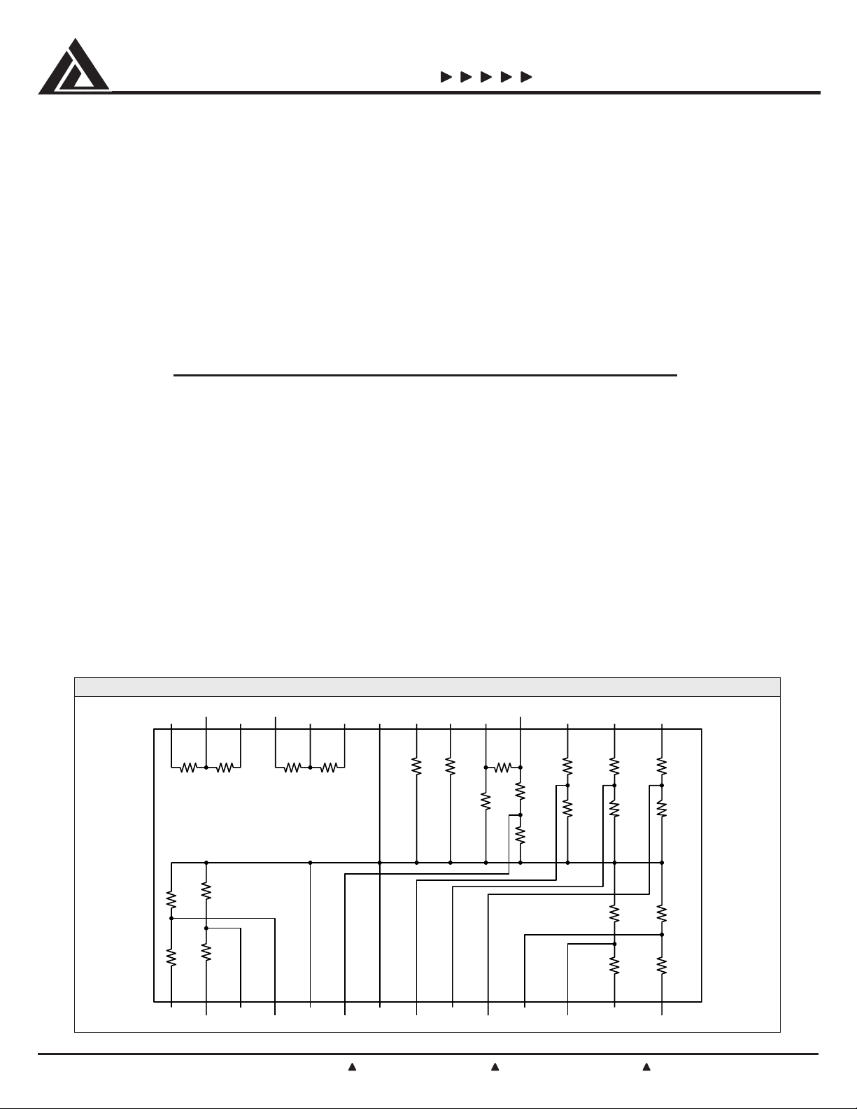
SCHEMATIC CONFIGURATION
R19
33KΩ
AC97CD_L
MIC_AMP_OUTAMP_OUT2AMP1–
R17
100KΩ
R18
4.7KΩ
AC97AUX_R
R13
6.8KΩ
R15
510KΩ
R16
100KΩ
R14
6.8 KΩ
AC97AUX_L AUXIN_R
AUXIN_L
R11
3.4KΩ
R12
3.4KΩ
R5
6.8KΩ
R6
6.8KΩ
MIC IN MIC+ MIC– CD_R CD_GND CD_L
2526 24 23 22 21 20 19 18 17 16 15
R22
R21
33KΩ
GND
22KΩ
AC97MIC
GND
R20
4.7KΩ
7 13
AC97CD_GND
AC97CD_R
R9
6.8KΩ
R10
6.8KΩ
R7
6.8KΩ
R8
6.8KΩ
C0441098
1
Page 2
CALIFORNIA MICRO DEVICES
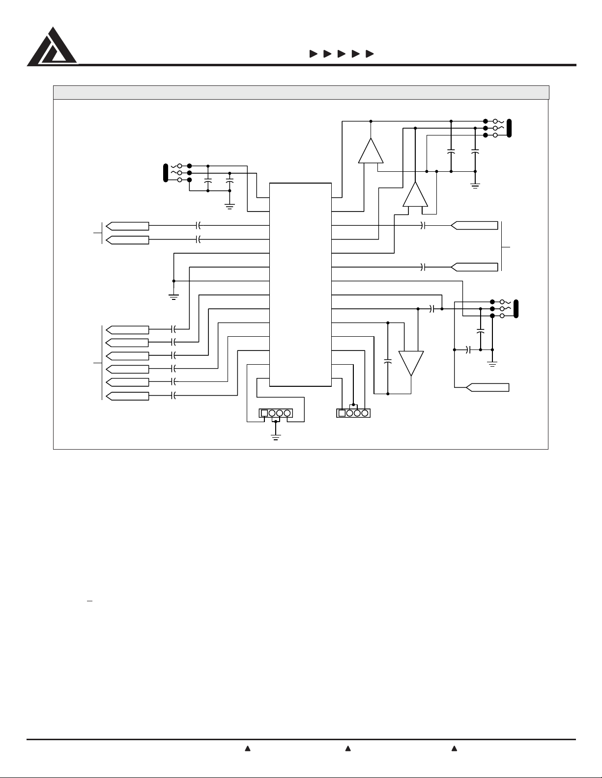
TYPICAL APPLICATIONS CIRCUIT
PACAC97
LINE OUT
TO
CODEC
TO
CODEC
R LINE IN
L LINE IN
MIC IN
R CD IN
CD GND IN
L CD IN
R AUX IN
L AUX IN
LINE IN
+
+
+
+
+
+
+
–
PACAC97
GND
+
+
P1
P2 P27P2 P27
P3 P26
P4 P25
P5 P24
P6 P23
P7 P22
P8 P21
P9 P20
P10 P19
P11 P18
P12 P17
P13 P16
P14
AUX IN
GND
P28
P15
ATAPI CD IN
+
–
+–
GND
R LINE OUT
L LINE OUT
MIC BIAS
GND
FROM
CODEC
MIC
R1, R2 and R3, R4 provide 6dB pads for the LINE-IN
stereo signals in order to scale a 2Vrms input to a
1Vrms Codec input. Similarly, R5, R6, R7, R8 and R9,
R10, R13, R14 provide the necessary attenuation for
the AUX and CD signals going to the Codec. With an
external Operational Amplifier, resistors R17 and R18
provide nominally 27dB of gain for the microphone
signal (non-inverting amp). R15, R16 divide down the
microphone output signal, thereby protecting the Codec
from any transient voltages coming from the microphone
amplifier. This is particularly important if this amplifier
runs of
+12V supplies. The R15/R16 divider can be
bypassed with an external 0Ω jumper connection, if so
desired. Bias voltage needs to be provided for condenser type microphones. Resistors R21, R22, R23 and
R24 are the gain setting resistors for the headphone
amplifier. The gain is set at 3.5dB with the output
amplifiers in an inverting configuration. The output gain
can be changed with the addition of external resistors,
©2000 California Micro Devices Corp. All rights reserved.
2
215 Topaz Street, Milpitas, California 95035 Tel: (408) 263-3214 Fax: (408) 263-7846 www.calmicro.com
allowing for maximum design flexibility. The resistors are
referenced as Amp1 and Amp2 rather then Left and
Right to provide added flexibility for board layout. LINEIN, LINE-OUT and MIC jack signals are externally decoupled in order to minimize EMI.
Crosstalk Test Circuit
Cross talk is a critical parameter for high quality audio.
Specifically, stereo cross talk (Left to Right) and channel
to channel cross talk must be minimized. For this reason
much attention has been paid to the circuit layout of the
PACAC97 in order to provide the necessary damping for
signals in the 20Hz–20KHz audio band. Three examples
are provided to illustrate inter-channel and channelchannel cross talk measurements that have been
performed on the PACAC97. Similar measurements were
performed for all audio functions deemed critical because of layout considerations.
9/27/2000
Page 3

CALIFORNIA MICRO DEVICES
Channel-to-Channel Crosstalk: Microphone CD
PACAC97
Figure 1 shows a cross talk measurement of the microphone to the Right Codec CD signal. The microphone
amplifier output pin (pin 18) is driven with a 2Vrms
signal. The Right CD Codec signal is terminated by a
2Vms
GND
18 MIC_AMP_OUT
510Ω
100Ω
6 AC97MIC 8
TP2
10KΩ
GND
Figure 1*.
Inter-channel Crosstalk: AMP2-AMP1 (LINE_OUT)
Figure 2 shows a crosstalk measurement of Left to Right
channel for the gain setting resistors of the headphone
amplifier (referred to as AMP1 and AMP2). The IN2
(output from Codec) and the AMP_OUT2 pin (pins 23
and 25) are driven by a 2Vrms source. The AMP_OUT1
is terminated by a 10KΩ resistor while the IN1 pin is
10KΩ load resistor while pins 5,7,17 and 22 on the
device are grounded. Crosstalk measured over the audio
band of 20Hz–20KHz is in excess of –90dB.
17
6.8KΩ
6.8KΩ
5,7,22
GND
GND
GND
AC97CD_R
TP1
10KΩ
terminated with a 1KΩ resistor which represents the
output impedance of the LINE_OUT output of the Codec.
Pins 5, 7, 22 and 24, on the device are grounded.
Crosstalk measured over the audio band of
20Hz to 20KHz is in excess of –90dB.
© 2000 California Micro Devices Corp. All rights reserved.
9/27/2000
215 Topaz Street, Milpitas, California 95035 Tel: (408) 263-3214 Fax: (408) 263-7846 www.calmicro.com
10KΩ
GND GND
28
33KΩ 22KΩ 33KΩ 22KΩ
1KΩ
26 25 24 23 5, 7, 2227
Figure 2*.
2Vms 2Vms
GND
GND
3
Page 4

CALIFORNIA MICRO DEVICES
Inter-channel Crosstalk: LINE_IN_L – LINE_IN_R
PACAC97
Figure 3 shows a cross talk measurement for Left to
Right channel for LINE_IN signals. The LINE_IN_L input
is driven by a 2Vrms source. Both AC97 LINE signals
device are grounded. Crosstalk from
AC97LINE_IN_L to AC97LINE_IN_R, measured over the
audio band of 20Hz to 20KHz, is in excess of –90 dB.
are loaded by 10KΩ resistors and pins 5,7 and 22 on the
6.8KΩ
6.8KΩ
1 LINE_IN_L 2 LINE_IN_R 3
2Vms
6.8KΩ
6.8KΩ
GND
10KΩ
GND
TP2
4
10KΩ
GND
5, 7, 22
TP1
GNDGND
Figure 3*.
egakcaPworraN-rebmuNtraPgniredrO
sniPelytSsebuTleeR&epaTgnikraMtraP
82POSQT/79CACAPR/79CACAPQ79CACAP
*Measurements made using Tektronix TDS684, 5GHz digitizing oscilloscope with passive probes.
NOITAMROFNIGNIREDROTRAPDRADNATS
©2000 California Micro Devices Corp. All rights reserved.
4
215 Topaz Street, Milpitas, California 95035 Tel: (408) 263-3214 Fax: (408) 263-7846 www.calmicro.com
9/27/2000
 Loading...