

Page 1
MICROTECHNOLOGY
1 2 3 4 5 6 7 8 9 10 11 12
24 23 22 21 20 19 18 17 16 15 14 13
LOAD
+5V
IS2
IS1
CC1
CC2
+Vb
GND
+OUT
+OUT
+OUT
+Vs
+Vs
RESET
STATUS
SHT DN
-IN
+IN
-Vb2
-Vb1
– OUT
– OUT
– OUT
– Vs
– Vs
Rcl**
PIN SIDE VIEW
* BYPASSING OF SUPPLIES IS REQUIRED
** SEE TEXT FOR OTHER CURRENT
LIMIT CONNECTIONS
PHASE COMPENSATION
GAIN Rc Cc
1 100 470pF
>3 SHORT 220pF
>10 SHORT 100pF
100 SHORT 10pF
Rc
Cc
**
*
*
*
*
POWER OPERATIONAL AMPLIFIER
PA17
HTTP://WWW.APEXMICROTECH.COM (800) 546-APEX (800) 546-2739
FEATURES
PRELIMINARY
• HIGH INTERNAL DISSIPATION — 850 WATTS
• HIGH VOLTAGE, HIGH CURRENT — 200V
50A CONTINUOUS, 100A PULSE
• HIGH SLEW RATE — 50V/µS
• 4 WIRE CURRENT LIMIT SENSING
• EXTERNAL SHUT DOWN CONTROL
• OPTIONAL BOOST VOLTAGE INPUTS
APPLICATIONS
• SEMI CONDUCTOR TESTING
• SONAR TRANSDUCER DRIVER
• LINEAR AND ROTARY MOTOR DRIVES
• YOKE/MAGNETIC FIELD EXCITATION
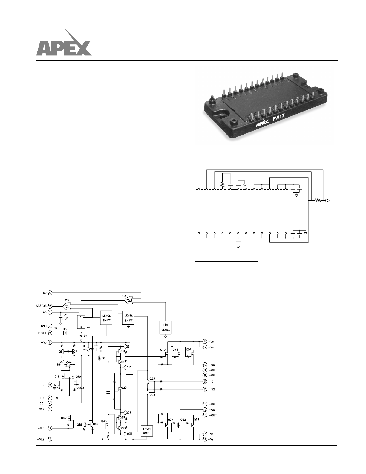
DESCRIPTION
The PA17 is a high voltage MOSFET power operational
amplifier that extends the performance limits of power amplifiers in slew rate and power bandwidth, while maintaining high
current and power dissipation ratings.
The PA17 is a highly flexible amplifier. The shutdown
feature allows ultra-low quiescent current for standby operation or load protection by disabling the entire amplifier. Boost
voltage inputs allow the small signal portion of the amplifier to
operate at a higher voltage than the high current output stage.
The amplifier is then biased to achieve close linear swings to
the supply rails at high currents for extra efficient operation.
External compensation tailors performance to user needs. A
four wire sense technique allows current limiting without the
need to consider internal or external milliohm parasitic resistance in the output line.
EXTERNAL CONNECTIONS
EQUIVALENT SCHEMATIC
APEX MICROTECHNOLOGY CORPORATION • TELEPHONE (520) 690-8600 • FAX (520) 888-3329 • ORDERS (520) 690-8601 • EMAIL prodlit@apexmicrotech.com
Page 2
PA17
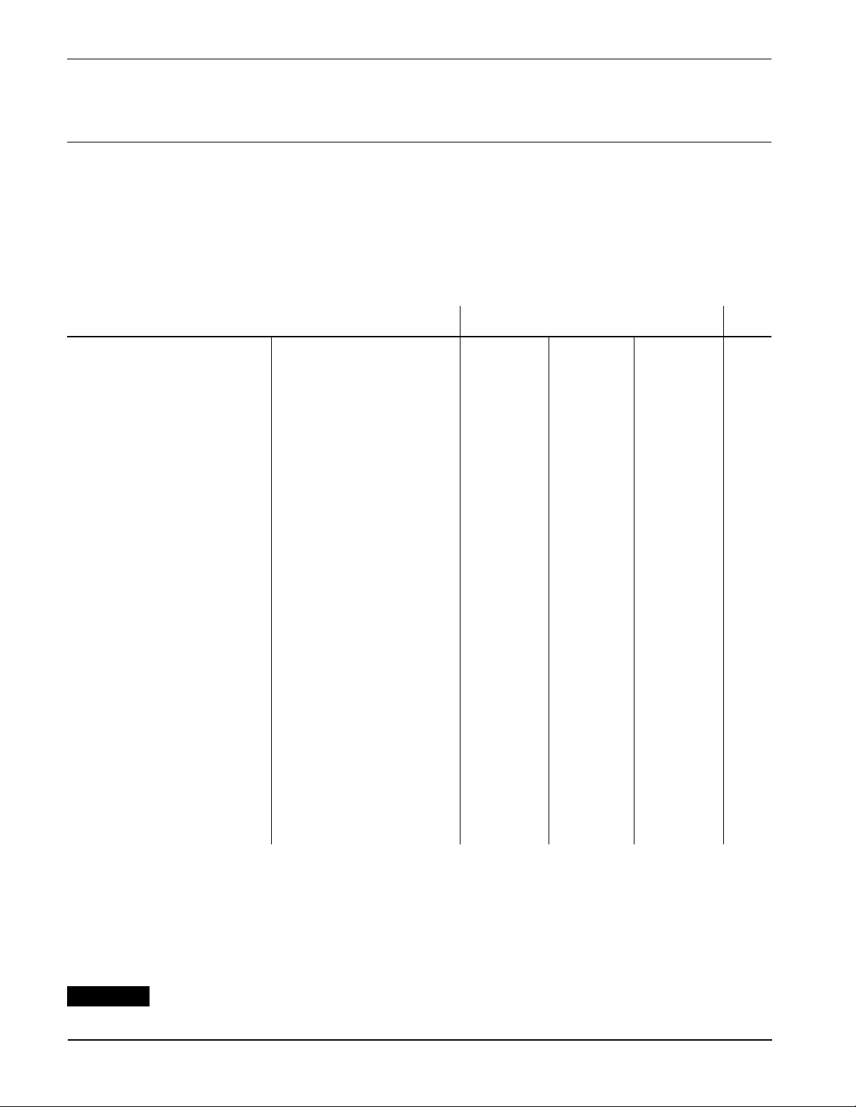
ABSOLUTE MAXIMUM RATINGS
SPECIFICATIONS
ABSOLUTE MAXIMUM RATINGS
SUPPLY VOLTAGE, +VS to –V
BOOST VOLTAGE ±VS±20V
S
200V
OUTPUT CURRENT, within SOA 100A
POWER DISSIPATION, internal 850W
INPUT VOLTAGE, differential ±20V
INPUT VOLTAGE, common mode ±V
TEMPERATURE, pin solder - 10s 300°C
TEMPERATURE, junction
2
B
150°C
TEMPERATURE, storage –65 to +150°C
OPERATING TEMPERATURE RANGE, case –25 to +85°C
SPECIFICATIONS
PARAMETER TEST CONDITIONS
INPUT
OFFSET VOLTAGE, initial 510mV
OFFSET VOLTAGE, vs. temperature Full temperature range 30 50 µV/°C
OFFSET VOLTAGE, vs. supply 15 µV/V
BIAS CURRENT, initial 10 50 pA
BIAS CURRENT, vs. supply .01 pA/V
OFFSET CURRENT, initial 10 50 pA
INPUT IMPEDANCE, DC 10
INPUT CAPACITANCE 4pF
COMMON MODE VOLTAGE RANGE Full temperature range ±VB 10 V
COMMON MODE REJECTION, DC Full temp. range, VCM = ±20V 86 98 dB
INPUT NOISE 100kHz BW, RS = 1KΩ 10 µVrms
GAIN
OPEN LOOP, @ 15Hz Full temperature range, CC = 100pF 94 102 dB
GAIN BANDWIDTH PRODUCT IO = 10A 2 MHz
POWER BANDWIDTH RL = 4.5Ω, VO = 180V p-p 90 kHz
1
MIN TYP MAX UNITS
11
Ω
±
PHASE MARGIN Full temperature range 60 °
OUTPUT
VOLTAGE SWING
VOLTAGE SWING
CURRENT, peak
5
5
5
IO = 50A ±VS 8.8 ±VS 7.5 V
±VB=±Vs ± 10V, IO = 50A ±VS 6.8 ±VS 5.5 V
±
±
100 A
±
±
SETTLING TIME to .1% 2.5 µs
SLEW RATE Cc= 100pF 40 50 V/µs
CAPACITIVE LOAD AV = +1 10 nF
POWER SUPPLY
VOLTAGE Full temperature range ±15 ±75 ±100 V
CURRENT, quiescent, boost supply 30 mA
CURRENT, quiescent, total 120 mA
CURRENT, quiescent, total, shutdown Full temperature range 22 mA
THERMAL
RESISTANCE, AC, junction to case
3
Full temperature range, F>60Hz .1 °C/W
RESISTANCE, DC, junction to case Full temperature range, F<60Hz .15 °C/W
RESISTANCE4, junction to air Full temperature range 10 °C/W
TEMPERATURE RANGE, case Meets full range specification –25 85 °C
NOTES 1. Unless otherwise noted: TC = 25°C. DC input specifications are ± value given. Power supply voltage is typical rating.
±VB= ±VS, Cc = 470pF, Rc=100Ω.
2. Long term operation at the maximum junction temperature will result in reduced product life. Derate internal power dissipation
to achieve high MTTF. For guidance, refer to the heatsink data sheet.
3. Rating applies if the output current alternates between both output transistors at a rate faster than 60 Hz.
4. The PA17 must be used with a heatsink or the quiescent power may drive the unit to junction temperatures higher than 150°C.
5. Parameter guaranteed but not tested.
CAUTION
APEX MICROTECHNOLOGY CORPORATION • 5980 NORTH SHANNON ROAD • TUCSON, ARIZONA 85741 • USA • APPLICATIONS HOTLINE: 1 (800) 546-2739
The PA17 is constructed from MOSFET transistors. ESD handling procedures must be observed.
Page 3

OPERATING CONSIDERATIONS
PA17
GENERAL
Please read Application Note 1 "General Operating Considerations" which covers stability, supplies, heat sinking, mounting, current limit, SOA interpretation, and specification interpretation. Visit www.apexmicrotech.com for design tools that
help automate tasks such as calculations for stability, internal
power dissipation, current limit; heat sink selection; Apex’s
complete Application Notes library; Technical Seminar Workbook; and Evaluation Kits.
CURRENT LIMIT
The positive and negative outputs of the PA17 must be
connected together by the user. However, the fact that multiple
pins share the output current allows for some unusual current
limit schemes not found in amplifiers with a single output pin.
Three pins each in the positive and negative outputs share
the output current of the PA17. Pins 8 and 10 of the positive
output and pins 15 and 17 of the negative output each carry
approximately 25% of the output current. Pin 9 of the positive
output and pin 16 of the negative output carry the remaining
50% of the output current .
For the current limit to operate correctly pin 3 (IS1) must be
connected to the amplifier output side and pin 2 (IS2) connected to the load side of the current limit resistor Rcl, as
shown in Figure 1. But Rcl may be connected to sample only
a fraction of the output current. With this method the current
limit resistor consumes less power and only slightly lowers the
overall accuracy of the current limit set point. Figure 1, shows
a circuit that samples only 25% of the output current. Only
those pins necessary to illustrate the current limit function are
shown in Figure 1.
FIGURE 1.
In addition, the current limit of the PA17 operates differently
than other Apex linear power amplifiers in that the output
current is not clamped at the current limit set point. Instead,
when an over-current condition is detected the PA17 sets
STATUS (pin 23) high. This flag can alert external circuitry to
do a variety of things to deal with this fault condition. For
example, when STATUS is connected directly to SD (pin 22)
the output stage of the PA17 is disabled until RESET (pin 24)
is toggled high (Figure 1). Another possibility would be to
connect STATUS to the SD pin via a RC circuit to delay the
shutdown of the output stage (Figure 2). This technique would
be useful if a short-term overload is normally expected that
does not exceed the safe operating area of the PA17. In still
another variation STATUS could trigger an external timer that
would periodically reset the PA17 until the fault is cleared.
STATUS, SHUTDOWN AND RESET FUNCTIONS
The 5V logic section of the PA17 provides control and
monitoring functions. The PA17 is protected from thermal
overloads by directly measuring the temperature of the output
transistors. When a thermal overload is detected the output
stage is latched off and the STATUS output goes high, indicating an alarm condition. A high on the RESET pin resets the
output stage. A high on the SHUTDOWN pin will also latch the
output stage off and forces the STATUS pin high. The SHUTDOWN pin can be used to put the PA17 in a standby mode to
lower the quiescent current and standby power dissipation. A
thermal overload immediately latches off the output stage and
cannot be delayed by external circuitry.
BOOST OPERATION
With the V
amplifier are operated at higher supply voltages than the
amplifier’s high current output stage. +V
–V
(pins 18, 19) are connected to the small signal circuitry
BOOST
of the amplifier. +V
connected to the high current output stage. An additional 10V
on the V
BOOST
to drive the output transistors into saturation and improve the
output voltage swing for extra efficient operation when required. When close swings to the supply rails is not required
the +V
BOOST
the –V
BOOST
at a voltage lower than the V
feature the small signal stages of the
BOOST
(pin 6) and
BOOST
(pins 11,12) and –VS (pins 13, 14) are
S
pins is sufficient to allow the small signal stages
and +VS pins must be strapped together as well as
and –VS pins. The boost voltage pins must not be
pins.
S
COMPENSATION
The external compensation components CC and RC are
connected to pins 4 and 5. Unity gain stability can be achieved
at any compensation capacitance greater than 330 pF with at
least 60 degrees of phase margin. At higher gains more phase
shift can be tolerated in most designs and the compensation
capacitance can accordingly be reduced, resulting in higher
bandwidth and slew rate. Use the typical operating curves as
a guide to select C
FIGURE 2.
APEX MICROTECHNOLOGY CORPORATION • TELEPHONE (520) 690-8600 • FAX (520) 888-3329 • ORDERS (520) 690-8601 • EMAIL prodlit@apexmicrotech.com
PA17U REV 3 JUNE 2000 © 2000 Apex Microtechnology Corp.
and RC for the application.
C
 Loading...