

Page 1
P6KE SERIES
600 WATT PEAK POWER TRANSIENT VOLTAGE SUPPRESSORS
VOLTAGE RANGE
6.8 to 440 Volts
FEATURES
* 600 Watts Surge Capability at 1ms
* Excellent clamping capability
* Low zener impedance
* Fast response time: Typically less than
1.0ps from 0 volt to BV min.
* Typical I less than 1 A above 10VR µ
* High temperature soldering guaranteed:
260 C / 10 seconds / .375"(9.5mm) lead
length, 5lbs.(2.3kg) tension
600 Watts Peak Power
5.0 Watts Steady State
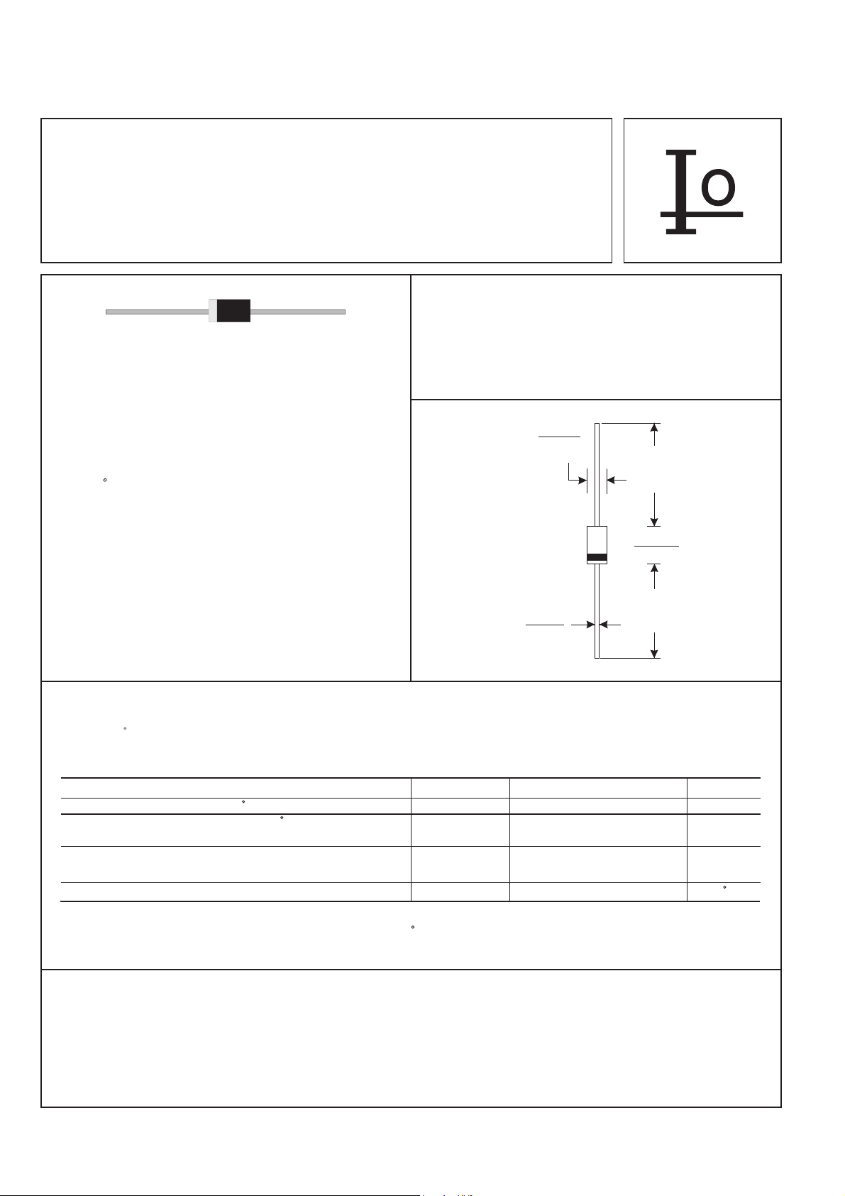
DO-15
.140(3.6)
.104(2.6)
DIA.
MECHANICAL DATA
* Case: Molded plastic
* Epoxy: UL 94V-0 rate flame retardant
* Lead: Axial leads, solderable per MIL-STD-202,
method 208 guranteed
* Polarity: Color band denotes cathode end
* Mounting position: Any
*
Weight: 0.40 grams
.034(.9)
.028(.7)
DIA.
Dimensions in inches and (millimeters)
MAXIMUM RATINGS AND ELECTRICAL CHARACTERISTICS
Rating 25 C ambient temperature uniess otherwies specified.
Single phase half wave, 60Hz, resistive or inductive load.
For capacitive load, derate current by 20%.
1.0(25.4)
MIN.
.300(7.6)
.230(5.8)
1.0(25.4)
MIN.
RATINGS SYMBOL VALUE UNITS
Peak Power Dissipation at T =25 C, T =1ms(NOTE 1) P Minimum 600 WattsA P PK
Steady State Power Dissipation at T =75 CL
Lead Length .375"(9.5mm) (NOTE 2)
Peak Forward Surge Current at 8.3ms Single Half Sine-Wave
superimposed on rated load (JEDEC method) (NOTE 3)
Operating and Storage Temperature Range T , T -55 to +175 CJ STG
NOTES:
1. Non-repetitive current pulse per Fig. 3 and derated above T =25 C per Fig. 2.
2. Mounted on Copper Pad area of 1.6" X 1.6" (40mm X 40mm) per Fig.5.
3. 8.3ms single half sine-wave, duty cycle = 4 pulses per minute maximum.
A
P 5.0 WattsD
I 100 AmpsFSM
DEVICES FOR BIPOLAR APPLICATIONS
1. For Bidirectional use C or CA Suffix for types P6KE6.8 thru P6KE440.
2. Electrical characteristics apply in both directions.
136
Page 2
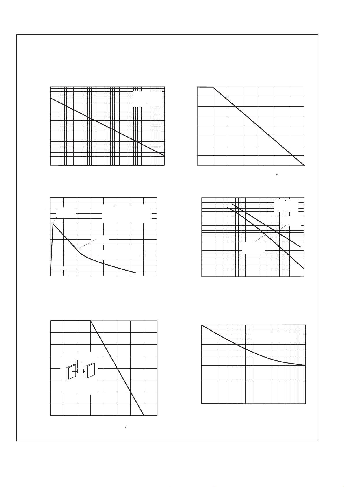
RATING AND CHARACTERISTIC CURVES (P6KE SERIES)
FIG.1-PEAK PULSE POWER DERATING CURVE
100
10
1.0
P , PEAK PULSE POWER, KWPPM
0.1
0.1 s 1.0 s 10 s 100 s 1.0ms 10ms µ µ µ µ
td, PULSE WIDTH, sec.
FIG.3-PULSE WAVE FORM
150
T =25 C
tf=10 s
µ
Peak Value
I
PPM
100
50
I , PEAK PULSE CURRENT, %PPM
td
0
0 1.0 2.0 3.0 4.0
A
Pulse Width (td) is defined
as the point where the Peak
Current Deacys to 50% of Ipp
Half Value-IPPM
2
10/1000 sec Waveform
µ
as Defined by R.E.A.
e-kt
t, TIME, ms
Non-Repetitive
Pulse Waveform
Shown in Fig. 3
T =25 CA
FIG.2-PULSE DERATING CURVE
100
75
PP PP
50
25
PEAK PULSE POWER(P ) OR CURRENT(I )
DERATING IN PERCENTAGE
0
0 25 50 75 100 125 150 175
T , AMBIENT TEMPERATURE ( C)A
FIG.4-TYPICAL JUNCTION CAPACITANCE
10,000
5,000
2,000
1,000
500
200
100
C , CAPACITANCE, pFJ
50
20
10
1.0 2.0 5.0 10 20 50 100 200
Measured at
Stand-Off
Voltage(V )MW
V(BR), BREAKDOWN VOLTAGE, VOLTS
T =25 C
f=1.0MHz
Vsig=50mVp-p
J
Measued at
Zero Bias
FIG.5-STEADY STATE POWER DERATING CURVE
5.00
3.75
L=.375"(9.5mm)
2.50
40mm x 40mm x 1mm
Copper Heat Sink
1.25
Pm( ), STEADY STATE POWER DISSIPATION, WATTSAV
(1.6" x 1.6" x .040")
0
0 25 50 75 100 125 150 175 200
T , LEAD TEMPERATURE ( C)L
137
FIG.6-MAXIMUM NON-REPETITIVE PEAK FORWARD
SURGE CURRENT, UNIDIRECTIONAL
100
T =T max
80
60
40
20
FSM
I , PEAK FORWARD SURGE
CURRENT, AMPERES
10
1 5 10 20 50 100
NUMBER OF CYCLES AT 60Hz
J J
8.3ms Single Half Sine-wave
JEDEC Method
Page 3

600 Watt Axial Lead TVS
UNI REVERSE BREAKDOWN BREAKDOWN TEST MAXIMUM PEAK REVERSE
DIRECTIONAL STAND-OFF VOLTAGE VOLTAGE CURRENT CLAMPING PULSE LEAKAGE
PART VOLTAGE VBR (V) VRB (V) IT VOLTAGE CURRENT @ VRWM
NUMBER VRWM (V) MIN. @IT MAX. @IT (mA) @Ipp Vc (V) Ipp (A) IR( A)
P6KE6.8 5.50 6.12 7.48 10 10.8 56.0 1000
P6KE6.8A 5.80 6.45 7.14 10 10.5 57.0 1000
P6KE7.5 6.05 6.75 8.25 10 11.7 51.0 500
P6KE7.5A 6.40 7.13 7.88 10 11.3 53.0 500
P6KE8.2 6.63 7.38 9.02 10 12.5 48.0 200
P6KE8.2A 7.02 7.79 8.61 10 12.1 50.0 200
P6KE9.1 7.37 8.19 10.00 1 13.8 44.0 50
P6KE9.1A 7.78 8.65 9.50 1 13.4 45.0 50
P6KE10 8.10 9.00 11.00 1 15.0 40.0 10
P6KE10A 8.55 9.50 10.50 1 14.5 41.0 10
P6KE11 8.92 9.90 12.10 1 16.2 37.0 5
P6KE11A 9.40 10.50 11.60 1 15.6 38.0 5
P6KE12 9.72 10.80 13.20 1 17.3 35.0 5
P6KE12A 10.20 11.40 12.60 1 16.7 36.0 5
P6KE13 10.50 11.70 14.30 1 19.0 32.0 5
P4KE13A 11.10 12.40 13.70 1 18.2 33.0 5
P6KE15 12.10 13.50 16.50 1 22.0 27.0 5
P6KE15A 12.80 14.30 15.80 1 21.2 28.0 5
P6KE16 12.90 14.40 17.60 1 23.5 26.0 5
P6KE16A 13.60 15.20 16.80 1 22.5 27.0 5
P6KE18 14.50 16.20 19.80 1 26.5 23.0 5
P6KE18A 15.30 17.10 18.90 1 25.2 24.0 5
P6KE20 16.20 18.00 22.00 1 29.1 21.0 5
P6KE20A 17.10 19.00 21.00 1 27.7 22.0 5
P6KE22 17.80 19.80 24.20 1 31.9 19.0 5
P6KE22A 18.80 20.90 23.10 1 30.6 20.0 5
P6KE24 19.40 21.60 26.40 1 34.7 17.0 5
P6KE24A 20.50 22.80 25.20 1 33.2 18.0 5
P6KE27 21.80 24.30 29.70 1 39.1 15.0 5
P6KE27A 23.10 25.70 28.40 1 37.5 16.0 5
P6KE30 24.30 27.00 33.00 1 43.5 14.0 5
P6KE30A 25.60 28.50 31.50 1 41.4 14.4 5
P6KE33 26.80 29.70 36.30 1 47.7 12.6 5
P6KE33A 28.20 31.40 34.70 1 45.7 13.2 5
P6KE36 29.10 32.40 39.60 1 52.0 11.6 5
P6KE36A 30.80 34.20 37.80 1 49.9 12.0 5
P6KE39 31.60 35.10 42.90 1 56.4 10.6 5
P6KE39A 33.30 37.10 41.00 1 53.9 11.2 5
P6KE43 34.80 38.70 47.30 1 61.9 9.6 5
P6KE43A 36.80 40.90 45.20 1 59.3 10.1 5
P6KE47 38.10 42.30 51.70 1 67.8 8.9 5
P6KE47A 40.20 44.70 49.40 1 64.8 9.3 5
P6KE51 41.30 45.90 56.10 1 73.5 8.2 5
P6KE51A 43.60 48.50 53.60 1 70.1 8.6 5
P6KE56 45.40 50.40 61.60 1 80.5 7.4 5
P6KE56A 47.80 53.20 58.80 1 77.0 7.8 5
P6KE62 50.20 55.80 68.20 1 89.0 6.8 5
P6KE62A 53.00 58.90 65.10 1 85.0 7.1 5
P6KE68 55.10 61.20 74.80 1 98.0 6.1 5
P6KE68A 58.10 64.60 71.40 1 92.0 6.5 5
P6KE75 60.70 67.50 82.50 1 108.0 5.5 5
P6KE75A 64.10 71.30 78.80 1 103.0 5.8 5
µ
142
Page 4

600 Watt Axial Lead TVS
UNI REVERSE BREAKDOWN BREAKDOWN TEST MAXIMUM PEAK REVERSE
DIRECTIONAL STAND-OFF VOLTAGE VOLTAGE CURRENT CLAMPING PULSE LEAKAGE
PART VOLTAGE VBR (V) VRB (V) IT VOLTAGE CURRENT @ VRWM
NUMBER VRWM (V) MIN. @IT MAX. @IT (mA) @Ipp Vc (V) Ipp (A) IR( A)
P6KE82 66.40 73.80 90.20 1 118.0 5.2 5
P6KE82A 70.10 77.90 86.10 1 113.0 5.4 5
P6KE91 73.70 81.90 100.00 1 131.0 4.7 5
P6KE91A 77.80 86.50 95.50 1 125.0 4.9 5
P6KE100 81.00 90.00 110.00 1 144.0 4.2 5
P6KE100A 85.50 95.00 105.00 1 137.0 4.5 5
P6KE110 89.20 99.00 121.00 1 158.0 3.9 5
P6KE110A 94.00 105.00 116.00 1 152.0 4.0 5
P6KE120 97.20 108.00 132.00 1 173.0 3.5 5
P6KE120A 102.00 114.00 126.00 1 165.0 3.7 5
P6KE130 105.00 117.00 143.00 1 187.0 3.3 5
P6KE130A 111.00 124.00 137.00 1 179.0 3.4 5
P6KE150 121.00 135.00 165.00 1 215.0 2.8 5
P6KE150A 128.00 143.00 158.00 1 207.0 2.9 5
P6KE160 130.00 144.00 176.00 1 230.0 2.7 5
P6KE160A 136.00 152.00 168.00 1 219.0 2.8 5
P6KE170 138.00 153.00 187.00 1 244.0 2.5 5
P6KE170A 145.00 162.00 179.00 1 234.0 2.6 5
P6KE180 146.00 162.00 198.00 1 258.0 2.4 5
P6KE180A 154.00 171.00 189.00 1 246.0 2.5 5
P6KE200 162.00 180.00 220.00 1 287.0 2.1 5
P6KE200A 171.00 190.00 210.00 1 274.0 2.2 5
P6KE220 175.00 198.00 242.00 1 344.0 1.8 5
P6KE220A 185.00 209.00 231.00 1 328.0 1.9 5
P6KE250 202.00 225.00 275.00 1 360.0 1.7 5
P6KE250A 214.00 237.00 263.00 1 344.0 1.8 5
P6KE300 243.00 270.00 330.00 1 430.0 1.4 5
P6KE300A 256.00 285.00 315.00 1 414.0 1.5 5
P6KE350 284.00 315.00 385.00 1 504.0 1.2 5
P6KE350A 300.00 332.00 368.00 1 482.0 1.3 5
P6KE400 324.00 360.00 440.00 1 574.0 1.1 5
P6KE400A 342.00 380.00 420.00 1 548.0 1.1 5
P6KE440 356.00 396.00 484.00 1 631.0 1.0 5
P6KE440A 376.00 418.00 462.00 1 600.0 1.0 5
µ
145
 Loading...