

Page 1
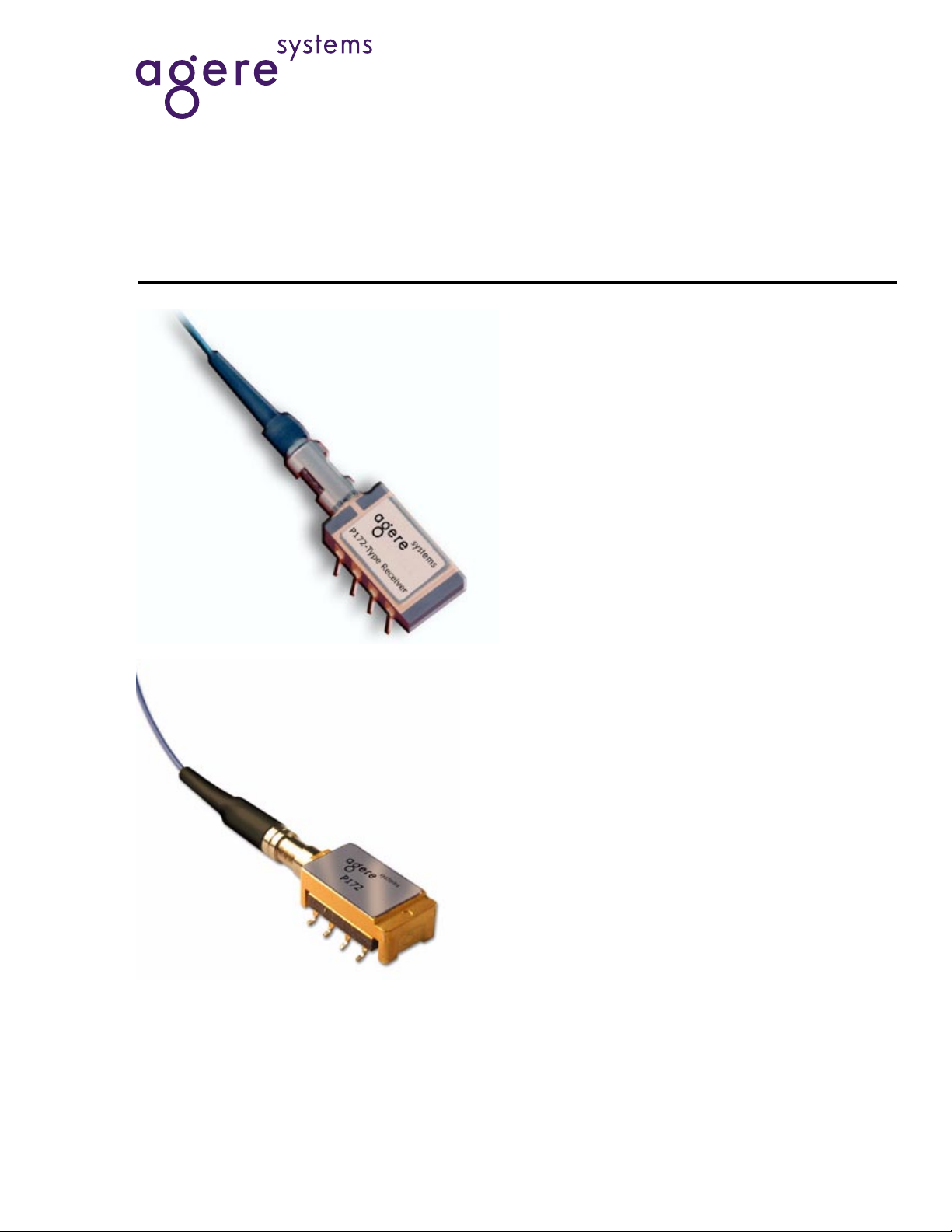
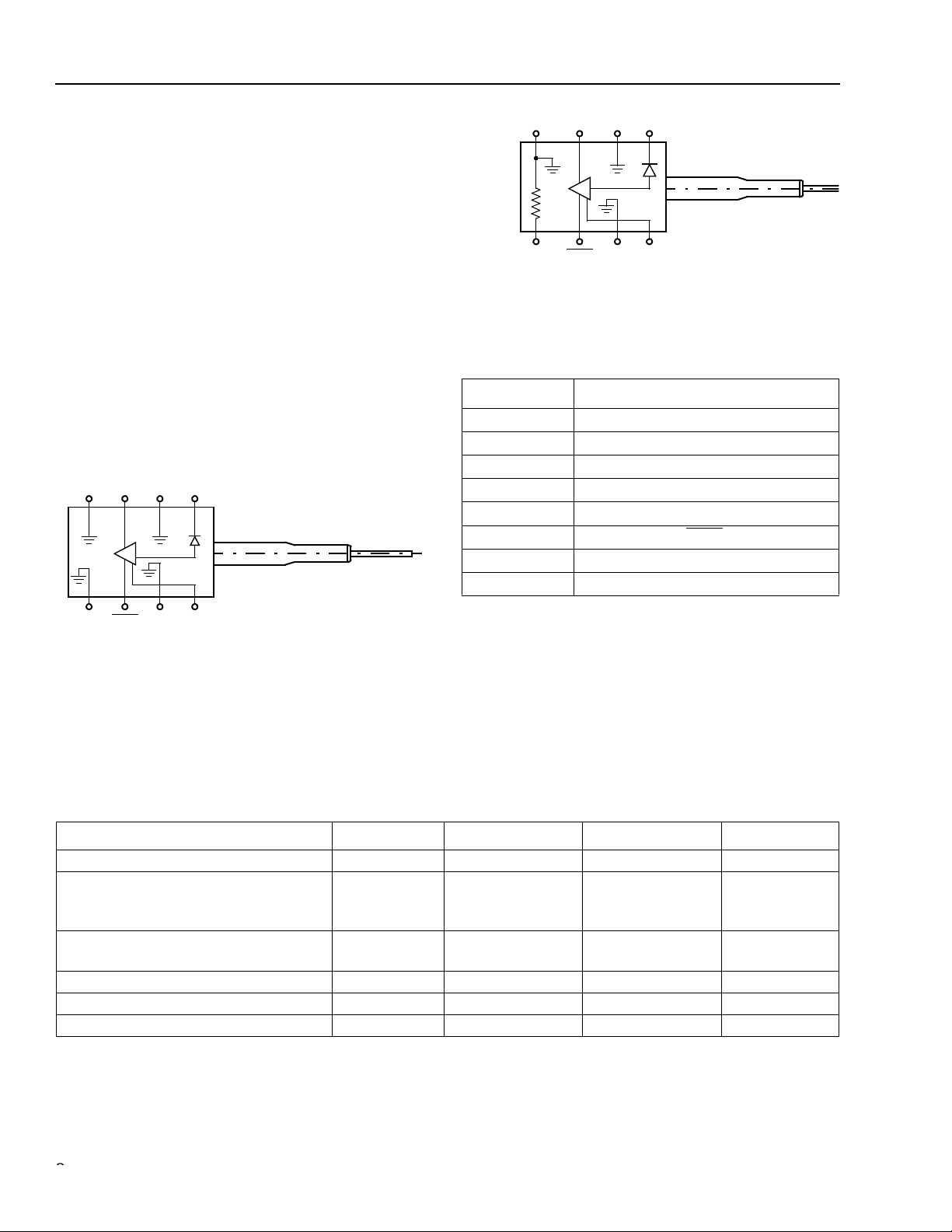
P172-Type Receiver
Advance Data Sheet
August 2001
Features
■
Low-profile, 8-lead mini-DIL or gull-wing style
package:
— Suitable for SONET/SDH applications
■
Metal package:
— Offers superior shielding for high noise
immunity
■
Planar structure for high reliability
■
Operating wavelength range:
— 1.25 µm—1.6 µm
The P172-Type PIN/Preamp and APD/Preamp receivers are
available in a mini-DIL package (top) or a gull-wing package
(bottom).
■
Available in 8 µm core single-mode fiber or
62.5 µm core multimode fiber pigtails
■
Wide operating temperature range:
— APD/PIN, –40 °C to +85 °C
■
Scheduled to be qualified according to
Technologies
■
Typical sensitivity:
™ GR-468-CORE
Telcordia
— APD, –32 dBm
— PIN, –23 dBm
■
Thermistor in APD version
Applications
■
Long-reach or metro SONET OC-48 and
SDH STM-16, or multidata-rate telecommunications applications
■
SONET/SDH receivers and transponders
■
Line terminal equipment
Benefits
■
Compact size
■
Easily board mounted
Page 2
Advance Data Sheet
P172-Type Receiver August 2001
DATA
Description
The P172-type receiver consists of a PIN or APD coupled to a single-mode or multimode fiber pigtail and a
linear preamplifier. Both the PIN and APD are rear-illuminated planar diode structures with a low-capacitance
active area for maximum responsivity and speed.
This device incorporates the new Laser 2000 manufacturing process from the Optoelectronics Products unit
of Agere Systems Inc. Laser 2000 is a low-cost platform that targets high-volume manufacturing and tight
product distributions on all optical subassemblies. This
platform incorporates an advanced optical design that
is produced on Agere Systems’ highly automated production lines. The Laser 2000 platform is qualified for
central office and uncontrolled environments, and can
be used for applications requiring high performance
and low cost.
GND GND
DATA V
4321
56
DATA
GND GND
Figure 1. P172P PIN/Preamp Schematic (Top View)
PD
78
V
CC
1-902(F).b
GND
4321
5678
THERMISTOR
Figure 2. P172A APD/Preamp (Top View)
Table 1. P172-Type PIN/Preamp and APD/Preamp
Pin Descriptions
Pin Number Description
1 Photodiode Bias
2 Case Ground
3DATA*
4 Case Ground
5 Thermis tor /Cas e Grou nd
6DATA
7 Case Ground
8V
* Logic high when light is on.
† Thermistor in APD version; case ground in PIN version
‡ Logic low when light is on.
DATA
GND V
GND
PD
V
CC
‡
CC
1-902(F).c
†
Absolute Maximum Ratings
Stresses in excess of the absolute maximum ratings can cause permanent damage to the device. These are absolute stress ratings only. Functional operation of the device is not implied at these or any other conditions in excess
of those given in the operational sections of the data sheet. Exposure to absolute maximum ratings for extended
periods can adversely affect device reliability.
Parameter Symbol Min Max Unit
Positive Supply Voltage V
Optical Input Power:
APD
PIN
Operating Case Temperature Range:
APD/PIN T
Storage Temperature Range T
Lead Soldering Temperature — — 250 °C
Lead Soldering Time — — 10 s
CC
IN
P
IN
P
C
stg
–0.5 4.0 V
—
—
0
8.0
dBm
dBm
–40 85 °C
–40 85 °C
2
2
Agere System s Inc.
Page 3
Advance Data Sheet
August 2001 P172-Type Receiver
Electrical Characteristics
Minimum and maximum values specified over operating case temperature range and end of life (EOL), and typical
values are for 25 °C and beginning of life (BOL), unless otherwise specified
Table 2. Electrical Characteristic
Parameter Symbol Min Typ Max Unit
dc Power Supply Voltages:
Positive Supply
APD Operating Bias Voltage
V
V
APD Operating Voltage Temperature Coefficient
PIN Operating Bias Voltage
V
dc Power Supply Currents:
Positive Supply
APD Bias Supply at V
PIN Bias Supply at V
OP
OP
I
I
I
dc Power Dissipation P
Small Signal (<10 µA) Transimpedance T
Input Noise Current (100 kHz—2 GHz) N
Output Return Loss (130 MHz—5 GHz) S
3 dB Bandwidth f
Thermistor resistance at 25 °C* R
CC
OP
—
OP
CC
APD
PIN
DISS
z
rms
22
C
TH
3.15
45
0.07
3.0
—
—
—
3.3
—
—
5.0
55
—
—
3.45
70
0.14
15
101
4
4
— 200 350 mW
1.7 2.5 3.1 kΩ
— 322 466 nArms
— –15 –9 dB
1.7 2.0 — GHz
9.5 10 10.5 kΩ
V
V
V/°C
V
mA
mA
mA
* The resistance of the thermistor is inversely proportional to the temperature. The temperature can be calculated from the resistance value
using the Steinhart-Hart equation: 1/T = A + B ln(R) + C ln(R)
C = 4.5421 x 10
–8
.
3
;
where A, B, and C are constants: A = 1.0267 x 10
–3
,
B = 2.565 x 10
–4
,
Agere Systems Inc.
3
Page 4

Advance Data Sheet
P172-Type Receiver August 2001
Optical Characteristics
Minimum and maximum values specified over operating case temperature range and end of life (EOL), and typical
values are for 25 °C and beginning of life (BOL), unless otherw is e speci fied .
Table 3. Optical Characteristics
Parameter Symbol Min Typ Max Unit
Optical Wavelength for Rated Sensitivity λ 1.25 — 1.6 µm
P
P
R
RMIN
RMAX
—
—
9.0
8.6
0.81
0.70
—
—
—
—
–6
0
—
—
—
—
—
—
–32.5
–31.5
–23
–22
–3
1
—
—
—
—
—
—
–31
–30
–22
–21
—
—
–27
–14
A/W
A/W
A/W
A/W
dBm
dBm
dBm
dBm
dBm
dBm
dB
dB
Responsivity (at 1310 nm, V
BIAS
= VOP):
APD at –30 dBm, 25 °C
APD at –30 dBm, –40 °C to +85 °C
PIN at –20 dBm, 25 °C
PIN at –20 dBm, –40 °C to +85 °C
Sensitivity (2.5 Gbits/s, 2
23
– 1 PRBS, 1 x 10
1310 nm, 8.2 dB Extinction Ratio, V
APD Version:
At 25 °C
At –40 °C to +85 °C
PIN Version:
At 25 °C
At –40 °C to +85 °C
Overload (2.5 Gbits/s, 2
23
– 1 PRBS, 1 x 10
1550 nm, 8.2 dB Extinction Ratio, V
APD Version
PIN Version
Optical Return Loss:
Single-mode Fiber
Multimode Fiber
BIAS
BIAS
–10
= VOP):
–10
BER,
= VOP):
BER,
4
Agere System s Inc.
Page 5

Advance Data Sheet
August 2001 P172-Type Receiver
Outline Diagrams
P172-Type Through-Hole Package
Dimensions are in inches and (millimeters).
0.045 (1.14)
0.010
(0.25)
LEAD TRIM
0.315
(8.00)
0.195
(4.95)
4321
5678
0.565
(14.35)
0.100
(2.54)
NOSE GEOMETRY
0.974
(24.74)
BEND LIMITER
0.016 (0.41) 8 PLACES
0.155
(3.94)
MIN.
0.144
(3.66)
0.900 µm
FIBER
0.170
(4.32)
0.300
(7.62)
0.010
(0.25)
8 PLACES
0.079
(2.01)
MIN
0.431
(10.95)
STANDOFF
0.010 (0.25) MAX
CONNECTOR
FIBER LENGTH
1-1057F
Agere Systems Inc.
5
Page 6

Advance Data Sheet
P172-Type Receiver August 2001
Outline Diagrams
(continued)
P172-Type Gull-Wing Package
Dimensions are in inches and (millimeters).
0.045 (1.14)
0.315
(8.00)
0.010
(0.25)
LEAD TRIM
0.195
(4.95)
4321
5678
0.565
(14.35)
0.100
(2.54)
NOSE GEOMETRY
0.974
(24.74)
MIN.
BEND LIMITER
0.016 (0.41) 8 PLACES
0.155
(3.94)
0.144
(3.66)
0.900 M
0.170
µ
FIBER
(4.32)
0.047 ± 0.008
(1.19 ± 0.20)
0.020 ± 0.005
(0.50)
0.079
(2.01)
MIN
0.431
(10.95)
STANDOFF
0.010(0.25) MAX
CONNECTOR
FIBER LENGTH
1-1057F.a
6
Agere System s Inc.
Page 7

Advance Data Sheet
y
g
g
y
August 2001 P172-Type Receiver
Qualification Information
The P172-type receiver is scheduled to complete the following qualification tests and meet the intent of
Technologies
Table 4. P172Type Qualification Information
Mechanical Shock
and Vibration
Thermal Shock MIL-STD-883
Lead Integrity MIL-STD-883
Solderability MIL-STD-883
Low Temperature
Storage
High Temperature
Storage
Temperature
Cycling
Damp Heat MIL-STD-883
Cyclic Moisture
Resistance
ESD Threshold
Internal Moisture MIL-STD-883
GR-468-CORE.
Test Reference Conditions Sample Size Pass/Fail Criteria
Telcordia Technologies
GR-468-CORE,
Section 8.3.2
Method 1011
Method 2004
Method 2003
—
—
Telcordia Technologies
GR-468-CORE,
Section 5.20
Method 103
Telcordia Technologies
GR-468-CORE,
Section 5.23
Telcordia Technologies
GR-468-CORE,
Section 5.22
Method 1018
500 g, 0.5 ms
Condition A, 20 g,
20 Hz to 2000 Hz,
4 min./cycle,
4 cycles
0°C to 100 °C,
20 c
cles
Condition A To Be Provided by
—To Be Provided by
–40 °C stora
2000 hours
85°C stora
2000 hours
–40 °C to +85 °C,
500 c
85 °C/85% RH
1000 hours
— 11 10% Responsivity
—6
— 11 Pieces After
e
e
cles
11 10% Responsivity
Change After Completion
of Both Tests
11 Physical Attributes and
Leak Check
the Supplier
the Supplier
11 10% Responsivity
Change After Completion
of Test
11 10% Responsivity
Change After Completion
of Test
11 10% Responsivity
Change After Completion
of Test
11 10% Responsivity
Change After Completion
of Test
Change After Completion
of Test
Telcordia
Max 5000 ppm Water
Thermal Shock
Test
Vapor After Other Test
Cells
—
—
Requirement
Telcordia
Agere Systems Inc.
7
Page 8

Advance Data Sheet
P172-Type Receiver August 2001
Ordering Information
Table 5. P172-Type Receiver Ordering Information
Product Code Detector Type Connector type Lead type Fiber type Comcode
P172ABCA APD SC/PC Through Hole SMF 108566076
P172ABCF APD FC/PC Through Hole SMF 108566084
P172ABCS APD LC Through Hole SMF TBD
P172ABCJ APD MU Through Hole SMF TBD
P172ACCA APD SC/PC Gull Wing SMF 109122325
P172ACCF APD FC/PC Gull Wing SMF TBD
P172ACCS APD LC Gull Wing SMF TBD
P172ACCJ APD MU Gull Wing SMF TBD
P172PBCA PIN SC/PC Through Hole SMF 108566100
P172PBCF PIN FC/PC Through Hole SMF 108566118
P172PBCS PIN LC Through Hole SMF TBD
P172PBCJ PIN MU Through Hole SMF TBD
P172PCCA PIN SC/PC Gull Wing SMF TBD
P172PCCF PIN FC/PC Gull Wing SMF TBD
P172PCCS PIN LC Gull Wing SMF TBD
P172PCCJ PIN MU Gull Wing SMF TBD
P172PBAA PIN SC/PC Through Hole MMF TBD
P172PBAF PIN FC/PC Through Hole MMF 109113274
P172PBAS PIN LC Through Hole MMF TBD
P172PBAJ PIN MU Through Hole MMF TBD
P172PCAA PIN SC/PC Gull Wing MMF TBD
P172PCAF PIN FC/PC Gull Wing MMF TBD
P172PCAS PIN LC Gull Wing MMF TBD
P172PCAJ PIN MU Gull Wing MMF TBD
Table 6. Related Product Information
Product Code Description Document Number
R485 2.5 Gbits/s Receiver with Clock Recovery DS01-005OPTO
R480 2.5 Gbits/s Receiver with CML Data Output DS01-011OPTO
Telcordia Technologies
For additional information, contact your Agere Systems Account Ma na ger or the following:
INTERNET:
E-MAIL:
N. AMERICA: Agere Systems Inc., 555 Union Boulevard, Room 30L-15P-BA, Allentown, PA 18109-3286
ASIA: Agere Systems Hong Kong Ltd., Suites 3201 & 3210-12, 32/F, Tower 2, The Gateway, Harbour City, Kowloon
EUROPE:
Agere Systems Inc. reserves the right to make changes to the product(s) or information contained herein without notice. No liability is assumed as a result of their use or application.
Copyright © 2001 Agere Systems Inc.
All Rights Reserved
August 2001
DS01-283OPTO (Replaces DS99-198L WP-2 )
is a trademark of Telcordia Technologies, Inc.
http://www.agere.com
docmaster@agere.com
1-800-372-2447
Tel. (852) 3129-2000
CHINA:
JAP AN:
Tel. (44) 7000 624624
, FAX 610-712-4106 (In CANADA:
(86) 21-5047-12 12
(81) 3-5421-160 0
, FAX (852) 3129-2020
(Shanghai),
(Tokyo), KOREA:
, FAX (44) 1344 488 045
1-800-553-2448
(86) 10-6522-5566
(82) 2-767-1850
, FAX 610-712-4106)
(Beijing),
(86) 755-695-7224
(Seoul), SINGAPORE:
(Shenzhen)
(65) 778-8833
, TAIWAN:
(886) 2-2725-5858
(Taipei)
 Loading...