

Page 1
■
■
77..00 xx 22..00 xx 00..88mmmm SSMMDD
■
Features
●
Top view white LED (7.0 x 2.0 x 0.8mm)
●
Super high brightness of surface mount LED
●
Lead frame package with individual 2 pins
●
Compatible to IR reflow soldering.
●
4000Pcs/Reel
■
Applications
●
General lighting
●
Decoration lighting
●
Indicator
■
Absolute Maximum Rating
Item Symbol
DC Forward Current
IF 75 mA
2
(Ta=25℃)
(Ta=25℃)
(Ta=25℃)(Ta=25℃)
Value Unit
OSXX7020C1A
■
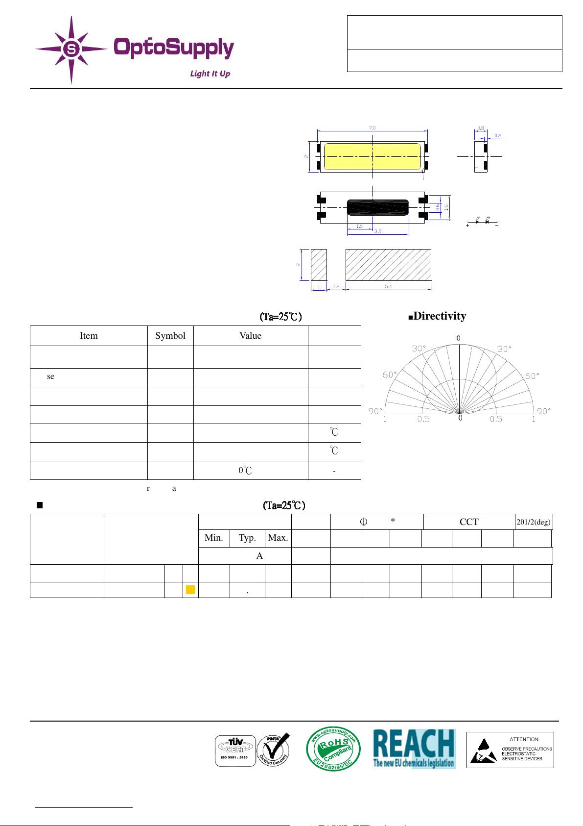
Outline Dimension
Top View
Back View
Recommended soldering Pad
■
Directivity
VVeerr..AA..11
1
Cathode ma rk
Side View
2
2, Anode 1, Cathode
Unit:mm
Tolerances: ±0.1mm
0
1
Pulse Forward Current*
Reverse Voltage
Power Dissipation
Operating Temperature
Storage Temperature
Lead Soldering Temperature
*Pulse width Max 0.1ms, Duty ratio max 1/10
■
Electrical -Optical Characteristics
IFP 150 mA
VR 10
PD 540
Topr -40 ~ +85
Tstg -40~ +85
Tsol 260℃/5sec
VF (V) IR(µA)
Part Number Color
Min. Typ. Max. Max. Min. Typ. Max. Min. Typ. Max. Typ.
IF=75mA VR=10V
OSW47020C1A
OSM57020C1A Warm White M
Note: * Vf tolerance: ±0.05V
* Luminous flux measurement allowance is:±10%
White W
5.8
5.8
(Ta=25
(Ta=25℃℃℃℃))))
(Ta=25(Ta=25
6.0 7.2
6.0 7.2
V
mW
℃
℃
-
0
Φ
v(lm)*
IF=75mA
CCT
2θ1/2(deg)
10 50 55 - 5500K - 7000K 120
10 45 50 - 2800K - 3500K 120
LED & Application Technologies
http://www.optosupply.com 1 VER A.0
Page 2
HIGH
TEMPERTURE
LOW
TEMPERTURE
TEMPERTURE
THERMAL
SOLDER
77..00 xx 22..00 xx 00..88mmmm SSMMDD
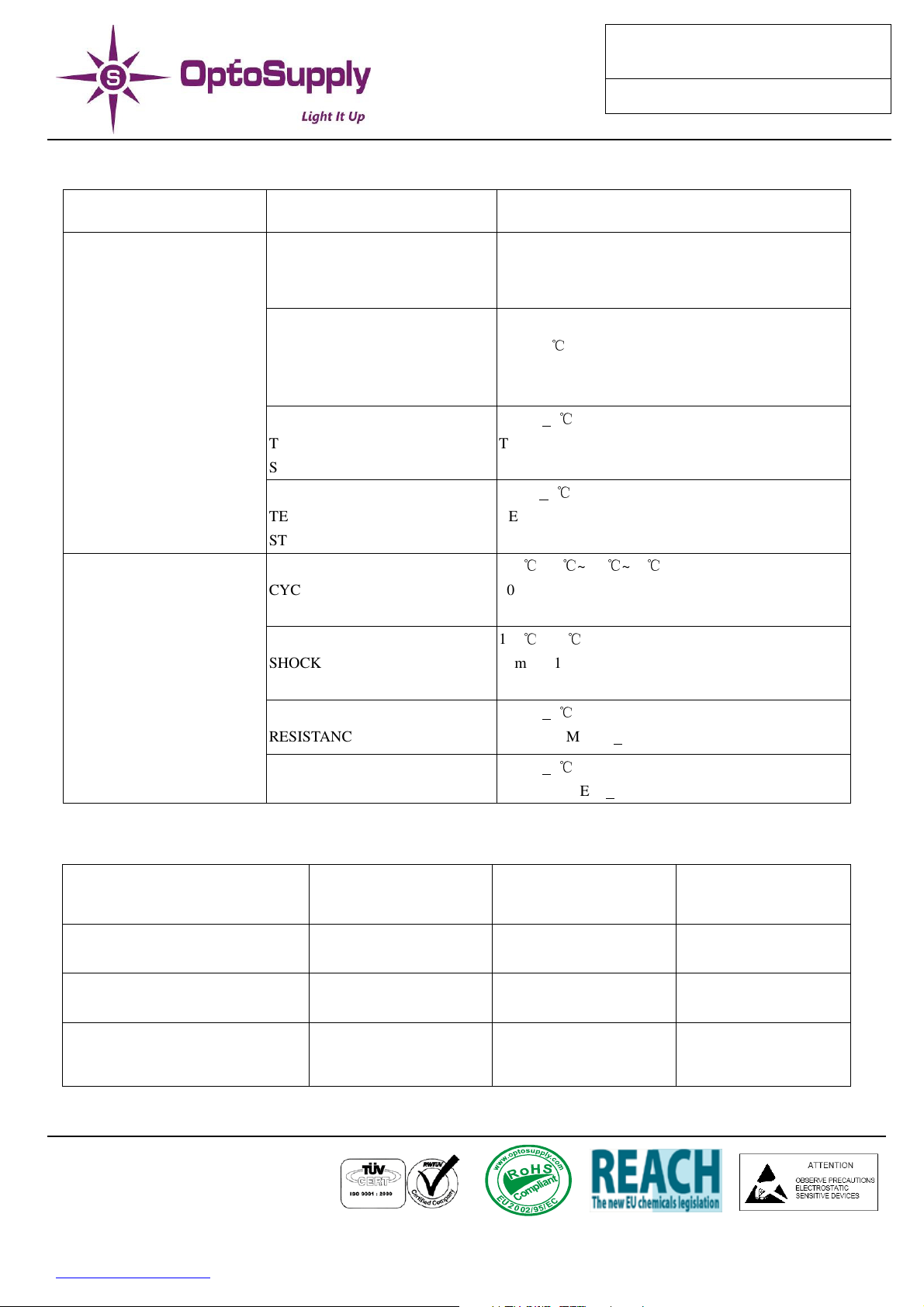
RELIABILITY TEST REPORT
CLASSIFICATION TEST ITEM TEST CONDTION
ENDURANCE TEST
ENVIRONMENTAL TEST
OPERATION
LIFE
HIGH
TEMPERTURE
HIGH HUMIDITY
STORAGE
STORAGE
STORAGE
CYCLING
SHOCK
RESISTANCE
If:75mA
Ta:25+5
TEST TIME=1000HRS(-24HRS,+72HRS)
R.H:90~95%
Ta:65+5℃
TEST TIME=240HRS(+2HRS)
Ta:105+5℃
TEST TIME=500HRS(-24HRS,+48HRS)
Ta:-55+5℃
TEST TIME=500HRS(-24HRS,+48HRS)
105℃~25℃~-55℃~25℃
60min 10min 60min 10min
20cycles
105℃~-55℃
10min 10min
10cycles
Ta:260+5℃
TEST TIME=10+1sec
OSXX7020C1A
VVeerr..AA..11
SOLDERABILITY Ta:230+5℃
TEST TIME=5+1sec
JUDGMENT CRITERIA OF FAILURE FOR THE RELIABILITY
MEASURING ITME SYMBOL CONDITIONS FAILURE
LUMINOUS INTENSITY IV IF=75mA
FORWARD VOLTAGE VF IF=75mA
REVERSE CURRENT IR Vr=10V IR>2*SPEC
LED & Application Technologies
IV<0.5*INITIAL
VALUE
VF>1.2*INITIAL
VALUE
http://www.optosupply.com 2 VER A.0
Page 3
77..00 xx 22..00 xx 00..88mmmm SSMMDD
■
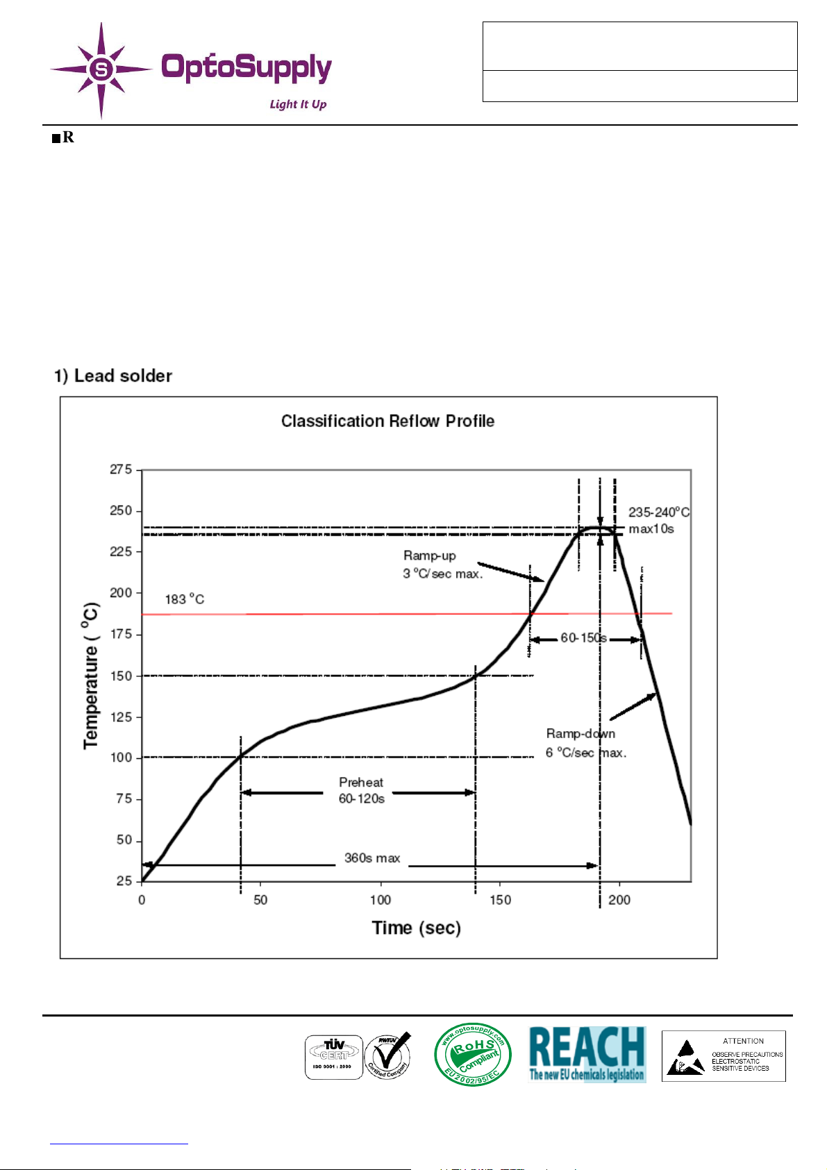
Recommended Reflow Soldering Profile
OSXX7020C1A
VVeerr..AA..11
Surface mounting condition
In automatic mounting of the SMD LEDs on printed circuit boards, any bending, expanding and pulling forces
or shock against the SMD LEDs should be kept min. to prevent them from electrical failures and mechanical
damages of the devices.
Soldering reflow
-Soldering of the SMD LEDs should conform to the soldering condition in the individual specifications.
-SMD LEDs are designed for reflow soldering.
-In the reflow soldering, too high temperature and too large temperature gradient such as rapid
heating/cooling may cause electrical & optical failures and damages of the devices.
-Wellypower can’t guarantee the LEDs after they have been assembled using the solder dipping method.
LED & Application Technologies
http://www.optosupply.com 3 VER A.0
Page 4
77..00 xx 22..00 xx 00..88mmmm SSMMDD
OSXX7020C1A
VVeerr..AA..11
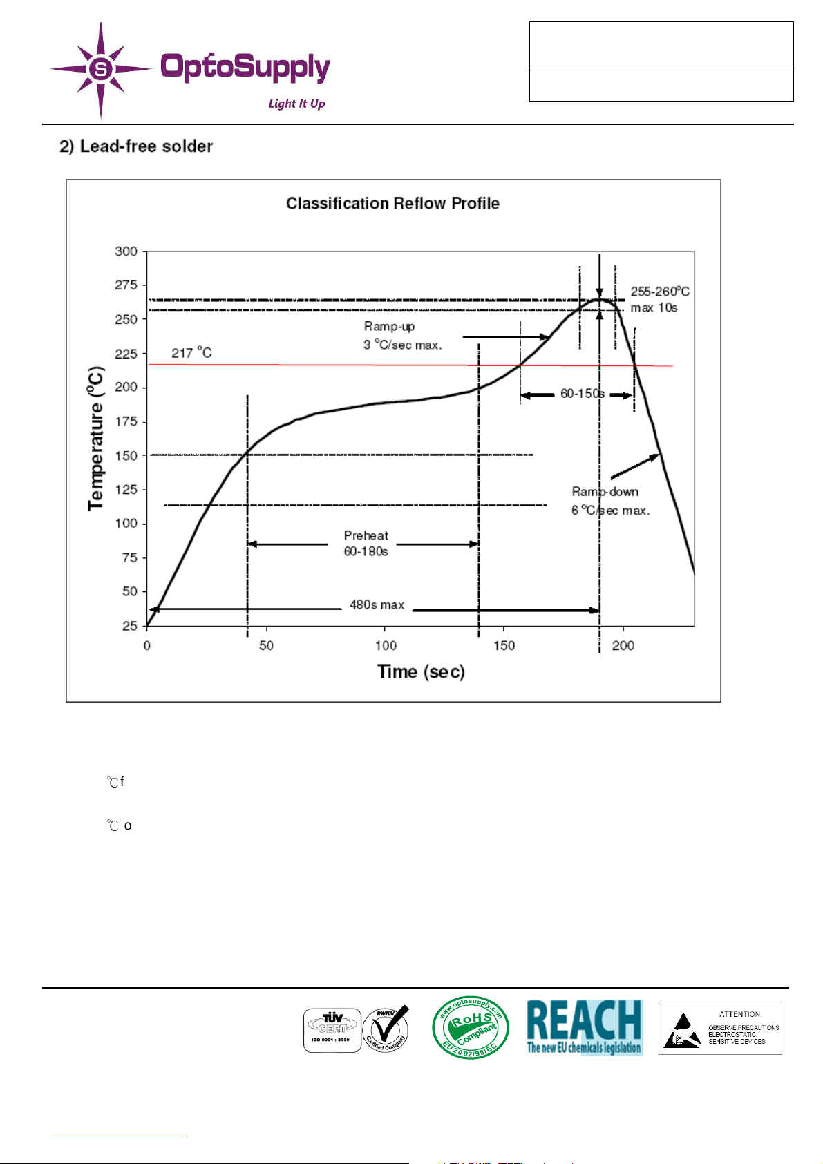
3) Manual soldering.
- Lead solder
Max. 300℃for max. 3sec, and only one time.
- Lead-free solder
Max. 350℃for max. 3sec, and only one time.
- There is possibility that the brightness of LEDs is decreased, which is influenced by heat or ambient
atmosphere during reflow. It is recommended to use the nitrogen reflow method use the nitrogen reflow
method.
- After LEDs have been soldered, repairs should not be done. As repair is unavoidable, a doublehead
soldering iron should be used. It should be confirmed beforehand whether the characteristics of the
LEDs will be damaged by repairing or not.
- Reflow soldering should not be done more than two times.
LED & Application Technologies
http://www.optosupply.com 4 VER A.0
 Loading...