

Page 1
Prod uct Bul le tin OPB680
April 1998
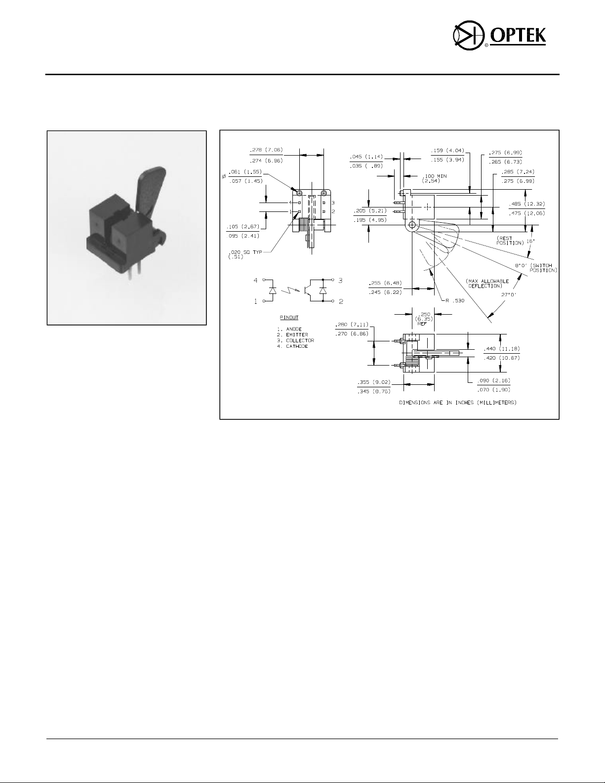
Slotted Optical Flag Switch
Types OPB680, OPB680-20
Fea tures
• Phototransistor output
• Mechanical switch replacement
• Printed circuit board mounting
• Enhanced signal to noise ratio
• Lever force options
De scrip tion
The OPB680 consists of an NPN
phototransistor and an infrared emitting
diode in a molded plastic housing. The
phototransistor has an enhanced low
current roll-off which improves contrast
ratio and immunity to background
irradiance. A lever arm actuated flag
interrupts the light beam, switching the
output between states that can readily
drive logic gates. The lever can be
actuated by a passing paper sheet
without damaging the paper edge.
The OPB680-20 has the same features
as the OPB680 with an increased lever
operating force. This feature prevents
false triggering due to incidental contact
in door sensing and other heavy duty
applications.
Customized lever arms and additional
spring torques can be designed for
specific applications.
Ab so lute Maxi mum Rat ings (TA = 25o C un less oth er wise noted)
Stor age and Op er at ing Tem pera ture . . . . . . . . . . . . . . . . . . . . . . . . -40o C to +100o C
Lead Sol der ing Tem pera ture [1/16 inch (1.6 mm) from case for 5 sec. with sol der ing
iron] . . . . . . . . . . . . . . . . . . . . . . . . . . . . . . . . . . . . . . . . . . . . . . . . . . . . . . . . . . 260o C
In put Di ode:
For ward DC Cur rent. . . . . . . . . . . . . . . . . . . . . . . . . . . . . . . . . . . . . . . . . . . . . . 50 mA
Peak For ward Cur rent (1 µs pulse width, 300 pps) . . . . . . . . . . . . . . . . . . . . . . . 3.0 A
Re verse DC Volt age. . . . . . . . . . . . . . . . . . . . . . . . . . . . . . . . . . . . . . . . . . . . . . . 3.0 V
Power Dis si pa tion . . . . . . . . . . . . . . . . . . . . . . . . . . . . . . . . . . . . . . . . . . . . 100 mW
(2)
Out put Pho to tran sis tor:
Collector- Emitter Volt age. . . . . . . . . . . . . . . . . . . . . . . . . . . . . . . . . . . . . . . . . . . . 30 V
Emit ter Re verse Cur rent. . . . . . . . . . . . . . . . . . . . . . . . . . . . . . . . . . . . . . . . . . . 10 mA
Col lec tor DC Cur rent . . . . . . . . . . . . . . . . . . . . . . . . . . . . . . . . . . . . . . . . . . . . . 30 mA
Power Dis si pa tion . . . . . . . . . . . . . . . . . . . . . . . . . . . . . . . . . . . . . . . . . . . . 200 mW
Notes:
(1) RMA flux is recommended. Duration can be extended to 10 sec. max. when flow soldering.
Max. 20 grams force may be applied to leads when soldering.
(2) Derate linearly 1.33 mW/o C above 25o C.
(3) Derate linearly 2.0 mW/o C above 25o C.
(4) “On” condition exists when the lever arm is in the rest position (16o from vertical) as shown in
the figure.
(5) “Off” condition exists when the lever arm is deflected clockwise 8o ± 3o from the rest position
(16o from vertical) as shown in the figure. Maximum allowable deflection is 35o from the rest
position.
(3)
Op tek Tech nol ogy, Inc. 1215 W. Crosby Road Car roll ton, Texas 75006 (972)323- 2200 Fax (972)323- 2396
23
Page 2
Types OPB680, OPB680-20
Elec tri cal Char ac ter is tics (TA = 25o C un less oth er wise noted)
SYM BOL PA RAME TER MIN MAX UNITS TEST CON DI TIONS
In put Di ode:
V
I
Out put Pho to tran sis tor:
V
(BR)CEO
I
ECO
I
CEO
Cou pled:
V
SAT
I
C(ON)
Me chani cal:
F
OP
Cycles Operating Cycles 100 K Cycles
Forward Voltage 1.60 V IF = 10 mA
F
Reverse Current 100
R
Collector-Emitter Breakdown Voltage 30 V
Emitter Reverse Current 100
Collector-Emitter Dark Current 100
Saturation Voltage 0.40 V
On-State Collector Current 600
VR = 3.0 mA
µA
IC = 100 µA
VEC = 0.4 V
µA
VCE = 5 V
µA
IF = 10 mA, IC = 100 µA
IF = 10 mA, VCE = 5 V
µA
Operating Force
OPB680 1.5 g Measured at end of lever
OPB680-20 20 g Measured at end of lever
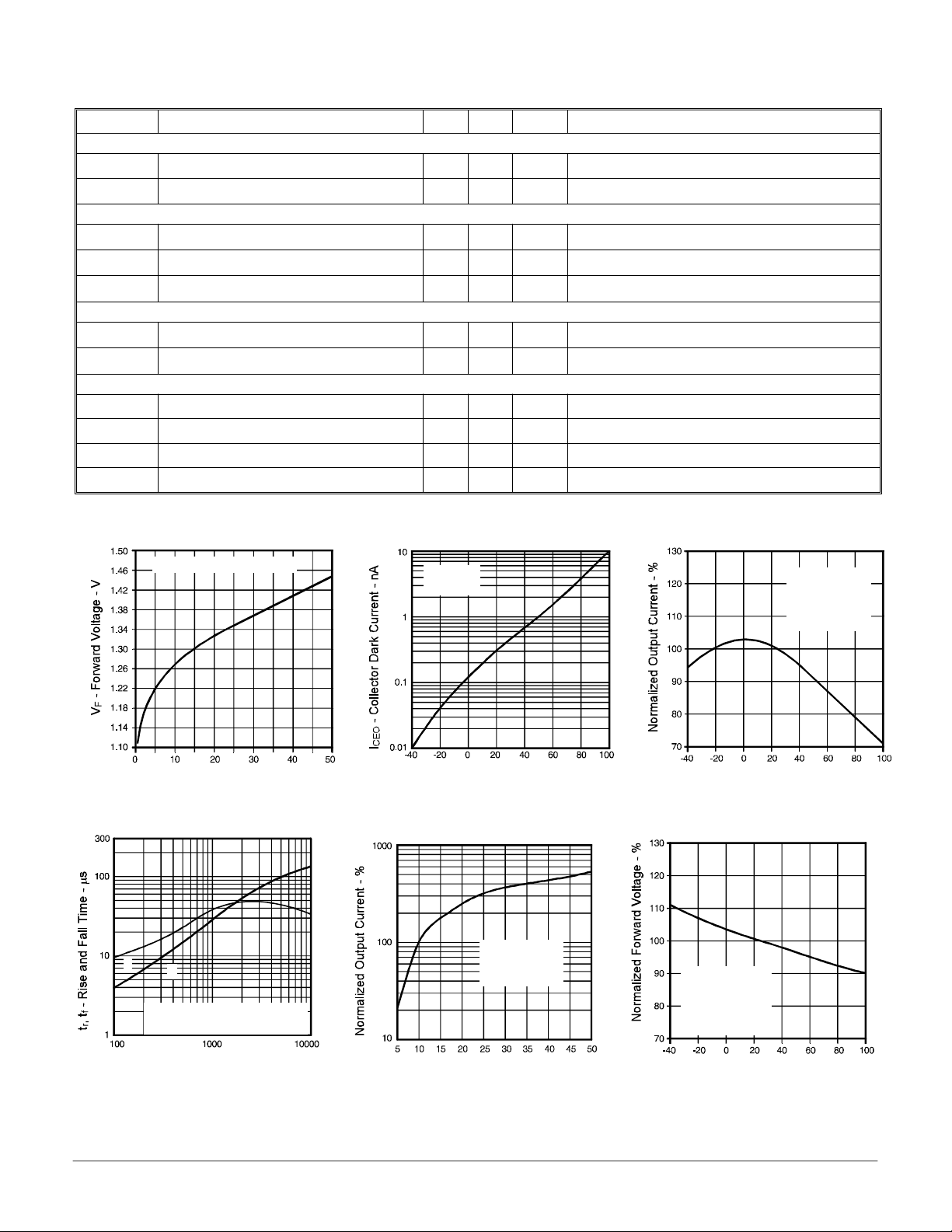
Forward Current vs. Forward
Voltage Input Diode
IF @ 500 mS pulse width
IF - Forward Current - mA
Rise and Fall Time vs. Load
t
r
Resistance
t
f
IF = 10 mA (50% Duty Cycle)
VCC = 5 V
Collector Dark Current vs. Ambient
Temperature
VCE = 5 V
IF = 0 mA
TA - Ambient Temperature - o C
Normalized Output Current
vs. Forward Current
VCE = 5 V
Normalized to
IF = 10 mA
Normalized Output Current vs.
Ambient Temperature
VCE = 5 V
IF = 10 mA
Normalized to
TA = 25o C
TA - Ambient Temperature - o C
Normalized Forward Voltage vs.
Ambient Temperature
VCE = 5 V
IF = 10 mA
Normalized to
TA = 25o C
RL - Load Resistance - Ω
IF - Forward Current - mA
TA - Ambient Temperature - oC
Op tek re serves the right to make changes at any time in or der to im prove de sign and to sup ply the best prod uct pos si ble.
Op tek Tech nol ogy, Inc. 1215 W. Crosby Road Car roll ton, Texas 75006 (972)323- 2200 Fax (972)323- 2396
24
 Loading...