

Page 1

Dual/Quad Single-Supply
FEATURES
Single-supply operation: 4.5 V to 33 V
Input common-mode includes ground
Output swings to ground
High slew rate: 3 V/μs
High gain bandwidth: 4 MHz
Low input offset voltage
High open-loop gain
No phase inversion
APPLICATIONS
Disk drives
Mobile phones
Servo controls
Modems and fax machines
Pagers
Power supply monitors and controls
Battery-operated instrumentation
Operational Amplifiers
OP292/OP492
PIN CONFIGURATIONS
OUTA
1
–V
OP292
2
3
TOP VIEW
(Not to Scale)
4
–INA
+INA
Figure 1. 8-Lead Narrow-Body SOIC (S-Suffix)
OUTA
1
2
–INA
+INA
3
OP492
TOP VIEW
+V
4
(Not to Scale)
5
+INB
6
–INB
OUTB
7
Figure 2. 14-Lead Narrow-Body SOIC (S-Suffix)
14
13
12
11
10
8
7
6
5
9
8
+V
OUTB
–INB
+INB
OUTD
–IND
+IND
–V
+INC
–INC
OUTC
00310-00
00310-002
GENERAL DESCRIPTION
The OP292/OP492 are low cost, general-purpose dual and quad
operational amplifiers designed for single-supply applications
and are ideal for 5 V systems.
Fabricated on Analog Devices, Inc., CBCMOS process, the
OP292/OP492 series has a PNP input stage that allows the input
voltage range to include ground. A BiCMOS output stage
enables the output to swing to ground while sinking current.
The OP292/OP492 series is unity-gain stable and features an
outstanding combination of speed and performance for singleor dual-supply operation. The OP292/OP492 provide a high
slew rate, high bandwidth, with open-loop gain exceeding
40,000 and offset voltage under 800 Ω (OP292) and 1 mV
(OP492). With these combinations of features and low supply
current, the OP292/OP492 series is an excellent choice for
battery-operated applications.
The OP292/OP492 series performance is specified for single- or
dual-supply voltage operation over the extended industrial
temperature range (−40°C to +125°C).
Rev. C
Information furnished by Analog Devices is believed to be accurate and reliable. However, no
responsibility is assumed by Analog Devices for its use, nor for any infringements of patents or other
rights of third parties that may result from its use. Specifications subject to change without notice. No
license is granted by implication or otherwise under any patent or patent rights of Analog Devices.
Trademarks and registered trademarks are the property of their respective owners.
One Technology Way, P.O. Box 9106, Norwood, MA 02062-9106, U.S.A.
Tel: 781.329.4700 www.analog.com
Fax: 781.461.3113 ©1993–2009 Analog Devices, Inc. All rights reserved.
Page 2

OP292/OP492
TABLE OF CONTENTS
Features .............................................................................................. 1
Applications ....................................................................................... 1
Pin Configurations ........................................................................... 1
General Description ......................................................................... 1
Revision History ............................................................................... 2
Specifications ..................................................................................... 3
Electrical Characteristics ............................................................. 3
Absolute Maximum Ratings ............................................................ 6
Thermal Resistance ...................................................................... 6
ESD Caution .................................................................................. 6
Typical Performance Characteristics ............................................. 7
Applications Information .............................................................. 13
Phase Reversal ............................................................................. 13
Power Supply Considerations ................................................... 13
Typical Applications ....................................................................... 14
Direct Access Arrangement for Telephone Line Interface ... 14
Single-Supply Instrumentation Amplifier .............................. 14
DAC Output Amplifier .............................................................. 14
50 Hz/60 Hz Single-Supply Notch Filter ................................. 15
Four-Pole Bessel Low-Pass Filter ............................................. 15
Low Cost, Linearized Thermistor Amplifier .............................. 15
Single-Supply Ultrasonic Clamping/Limiting Receiver
Amplifier ..................................................................................... 16
Precision Single-Supply Voltage Comparator ........................ 16
Programmable Precision Window Comparator .................... 16
Outline Dimensions ....................................................................... 17
Ordering Guide .......................................................................... 17
REVISION HISTORY
5/09—Rev. B to Rev. C
Deleted 8-Lead PDIP and 14-Lead PDIP ........................ Universal
Changes to Features Section and General Description Section . 1
Changed V
Changes to Table 3 and Table 4 ....................................................... 6
Changes to Figure 21 Caption and Figure 24 Caption .............. 10
Changes to Figure 29 ...................................................................... 11
Changes to Figure 35 ...................................................................... 13
Deleted OP292 SPICE Macro-model Section ............................. 14
Changes to Figure 38 ...................................................................... 14
Changes to Figure 39 and Figure 41 ............................................. 15
Deleted OP492 SPICE Macro-model Section ............................. 16
Changes to Figure 44 ...................................................................... 16
Updated Outline Dimensions ....................................................... 17
Changes to Ordering Guide .......................................................... 17
10/02—Rev. A to Rev. B
Edits to Outline Dimensions ......................................................... 18
1/02—Rev. 0 to Rev. A
Deleted Wafer Test Limits ............................................................... 4
Deleted Dice Characteristics ........................................................... 4
Edits to Ordering Guide ................................................................ 20
= 5 V to VS = ±15 V .................................................... 4
S
Rev. C | Page 2 of 20
Page 3

OP292/OP492
SPECIFICATIONS
ELECTRICAL CHARACTERISTICS
VS = 5 V, VCM = 0 V, VO = 2 V, TA = 25°C, unless otherwise noted.
Table 1.
Parameter Symbol Conditions Min Typ Max Unit
INPUT CHARACTERISTICS
Offset Voltage
OP292 VOS 0.1 0.8 mV
−40°C ≤ TA ≤ +85°C 0.3 1.2 mV
−40°C ≤ TA ≤ +125°C 0.5 2.5 mV
OP492 VOS 0.1 1 mV
−40°C ≤ TA ≤ +85°C 0.3 1.5 mV
−40°C ≤ TA ≤ +125°C 0.5 2.5 mV
Input Bias Current IB 450 700 nA
−40°C ≤ TA ≤ +85°C 0.75 2.5 μA
−40°C ≤ TA ≤ +125°C 3.0 5.0 μA
Input Offset Current IOS 7 50 nA
−40°C ≤ TA ≤ +85°C 100 700 nA
−40°C ≤ TA ≤ +125°C 0.4 1.2 μA
Input Voltage Range 0 4.0 V
Common-Mode Rejection Ratio CMRR VCM = 0 V to 4.0 V 75 95 dB
−40°C ≤ TA ≤ +85°C 70 93 dB
−40°C ≤ TA ≤ +125°C 65 90 dB
Large Signal Voltage Gain AVO R
−40°C ≤ TA ≤ +85°C 10 100 V/mV
−40°C ≤ TA ≤ +125°C 5 50 V/mV
Offset Voltage Drift ΔVOS/ΔT −40°C ≤ TA ≤ +125°C 2 10 μV/°C
Long-Term VOS Drift1 ΔVOS/ΔT 1 μV/Month
Bias Current Drift ΔIB/ΔT −40°C ≤ TA ≤ +85°C 6 pA/°C
−40°C ≤ TA ≤ +125°C 400 pA/°C
Offset Current Drift ΔIOS/ΔT −40°C ≤ TA ≤ +85°C 1.5 pA/°C
−40°C ≤ TA ≤ +125°C 2 pA/°C
OUTPUT CHARACTERISTICS
Output Voltage Swing
High V
RL = 100 kΩ to GND
OUT
−40°C ≤ TA ≤ +125°C 4.0 4.3 V
R
−40°C ≤ TA ≤ +125°C 3.7 3.9 V
Low V
R
OUT
−40°C ≤ TA ≤ +125°C 12 20 mV
R
−40°C ≤ TA ≤ +125°C 300 550 mV
Short-Circuit Current Limit I
5 8 mA
SC
POWER SUPPLY
Power Supply Rejection Ratio PSRR VS = 4.5 V to 30 V, VO = 2 V 75 95 dB
−40°C ≤ TA ≤ +125°C 70 90 dB
Supply Current Per Amp ISY VO = 2 V 0.8 1.2 mA
= 10 kΩ, VO = 0.1 V to 4 V 25 200 V/mV
L
= 2 kΩ to GND 3.8 4.1 V
L
= 100 kΩ to V+ 8 20 mV
L
= 2 kΩ to V+ 280 450 mV
L
Rev. C | Page 3 of 20
Page 4

OP292/OP492
Parameter Symbol Conditions Min Typ Max Unit
DYNAMIC PERFORMANCE
Slew Rate SR RL = 10 kΩ 3 V/μs
−40°C ≤ TA ≤ +125°C 1 2 V/μs
Gain Bandwidth Product GBP 4 MHz
Phase Margin φm 75 Degrees
Channel Separation CS fO = 1 kHz 100 dB
NOISE PERFORMANCE
Voltage Noise en p-p 0.1 Hz to 10 Hz 25 μV p-p
Voltage Noise Density en f = 1 kHz 15 nV/√Hz
Current Noise Density in 0.7 pA/√Hz
1
Long-term offset voltage drift is guaranteed by 1,000 hours life test performed on three independent wafer lots at 125°C with LTPD of 1.3.
V
=±15 V, VCM = 0 V, VO = 2 V, TA = 25°C, unless otherwise noted.
S
Table 2.
Parameter Symbol Conditions Min Typ Max Unit
INPUT CHARACTERISTICS
Offset Voltage
OP292 V
−40°C ≤ TA ≤ +85°C 1.2 2.5 mV
−40°C ≤ TA ≤ +125°C 1.5 3 mV
OP492 VOS 1.4 2.5 mV
−40°C ≤ TA ≤ +85°C 1.7 2.8 mV
−40°C ≤ TA ≤ +125°C 2 3 mV
Input Bias Current IB 375 700 nA
−40°C ≤ TA ≤ +125°C 0.5 1 μA
Input Offset Current IOS 7 50 nA
−40°C ≤ TA ≤ +85°C 20 100 nA
−40°C ≤ TA ≤ +125°C 0.4 1.2 μA
Input Voltage Range1 −11 +11 V
Common-Mode Rejection Ratio CMRR VCM = ±11 V 78 100 dB
−40°C ≤ TA ≤ +125°C 75 95 dB
Large Signal Voltage Gain AVO RL = 10 kΩ, VO =±10 V 25 120 V/mV
−40°C ≤ TA ≤ +85°C 10 75 V/mV
−40°C ≤ TA ≤ +125°C 5 60 V/mV
Offset Voltage Drift ΔVOS/ΔT −40°C ≤ TA ≤ +125°C 4 10 μV/°C
Bias Current Drift ΔIB/ΔT −40°C ≤ TA ≤ +125°C 3 pA/°C
OUTPUT CHARACTERISTICS
Output Voltage Swing VO RL = 2 kΩ to GND ±11 ±12.2 V
−40°C ≤ TA ≤ +125°C ±10 ±11 V
R
−40°C ≤ TA ≤ +125°C ±13.5 ±14.0 mV
Short-Circuit Current Limit ISC Short circuit to GND 8 10.5 mA
POWER SUPPLY
Power Supply Rejection Ratio PSRR VS = ±2.25 V to ±15 V 75 86 dB
−40°C ≤ TA ≤ +125°C 70 83 dB
Supply Current Per Amp ISY VO = 0 V 1 1.4 mA
1.0 2.0 mV
OS
= 100 kΩ to GND ±13.8 ±14.3 V
L
Rev. C | Page 4 of 20
Page 5

OP292/OP492
Parameter Symbol Conditions Min Typ Max Unit
DYNAMIC PERFORMANCE
Slew Rate SR RL =10 kΩ 2.5 4 V/μs
−40°C ≤ TA ≤ +125°C 2 3 V/μs
Gain Bandwidth Product GBP 4 MHz
Phase Margin φm 75 Degrees
Channel Separation CS fO = 1 kHz 100 dB
NOISE PERFORMANCE
Voltage Noise en p-p 0.1 Hz to 10 Hz 25 μV p-p
Voltage Noise Density en f = 1 kHz 15 nV/√Hz
Current Noise Density in 0.7 pA/√Hz
1
Input voltage range is guaranteed by CMRR tests.
Rev. C | Page 5 of 20
Page 6
OP292/OP492
ABSOLUTE MAXIMUM RATINGS
Table 3.
Parameter Rating
Supply Voltage 33 V
Input Voltage Range1 −15 V to +14 V
Differential Input Voltage1 V
Output Short-Circuit Duration Unlimited
Storage Temperature Range −65°C to +150°C
Operating Temperature Range −40°C to +125°C
Junction Temperature Range −65°C to +125°C
Lead Temperature Range (Soldering, 60 sec) 300°C
1
For supply voltages less than 36 V, the absolute maximum input voltage is
equal to the supply voltage.
1
Stresses above those listed under Absolute Maximum Ratings
may cause permanent damage to the device. This is a stress
rating only; functional operation of the device at these or any
other conditions above those indicated in the operational
section of this specification is not implied. Exposure to absolute
maximum rating conditions for extended periods may affect
device reliability.
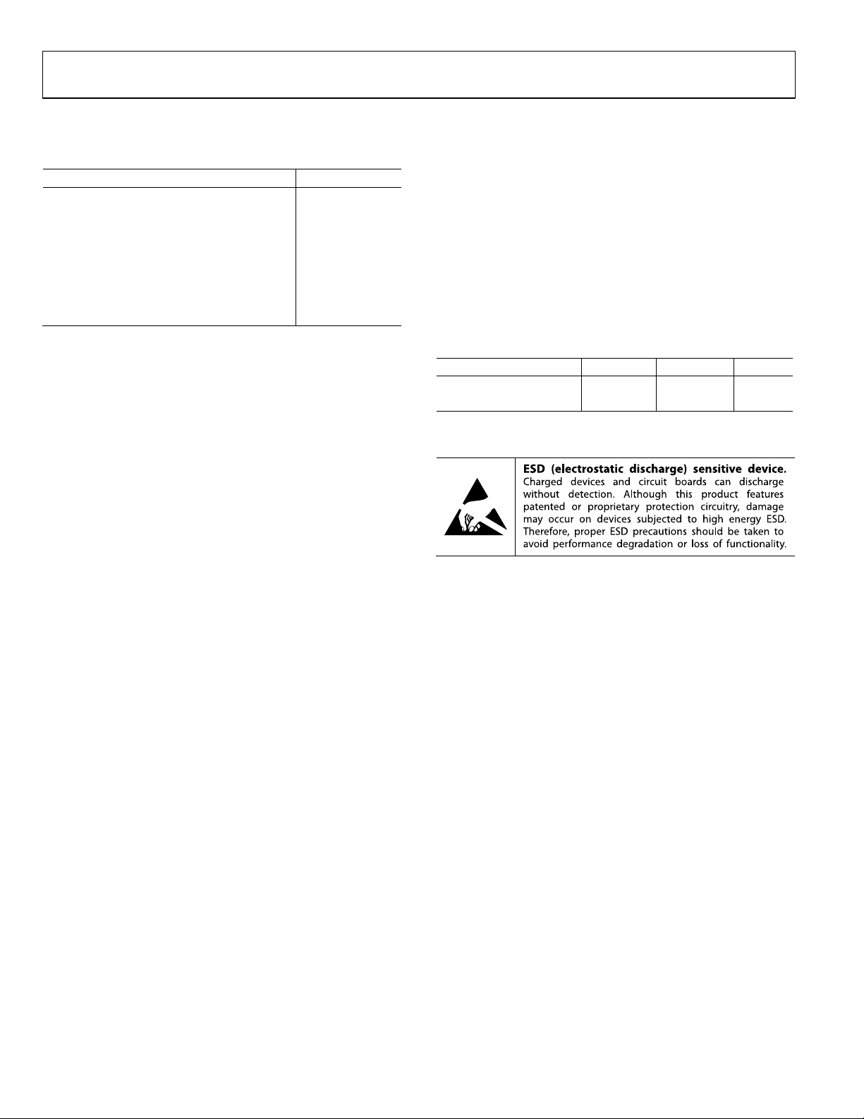
THERMAL RESISTANCE
θJA is specified for the worst-case conditions, that is, a device
soldered in the circuit board for the surface-mount packages.
Table 4. Thermal Resistance
Package Type θJA θ
8-Lead SOIC 158 43 °C/W
14-Lead SOIC 120 36 °C/W
Unit
JC
ESD CAUTION
Rev. C | Page 6 of 20
Page 7

OP292/OP492
TYPICAL PERFORMANCE CHARACTERISTICS
200
175
150
125
VS = 5V
V
= 0V
CM
T
= 25°C
A
720 OP AMPS
160
140
120
100
VS = 5V
V
= 0V
CM
T
= 25°C
A
600 OP AMPS
100
UNITS
75
50
25
0
INPUT OFFSET VOLTAGE, V
(µV)
OS
Figure 3. OP292 Input Offset Voltage Distribution @ 5 V
320
VS = ±15V
V
= 0V
CM
280
T
= 25°C
A
720 OP AMPS
240
200
160
UNITS
120
80
40
0
INPUT OFFSET VOLTAGE, V
.6
(mV)
OS
Figure 4. OP292 Input Offset Voltage Distribution @ ±15 V
160
140
120
VS = 5V
V
= 0V
CM
–40°C ≤ T
A
600 OP AMPS
≤ +125°C
80
UNITS
60
40
20
00310-003
500–400 400–500 3002001000–100–200–300
0
INPUT OFFSET VOLTAGE, VOS(mV)
0.6–0.4 0.5–0.5 0.40. 30.20.10–0.1–0.2–0.3
00310-006
Figure 6. OP492 Input Offset Voltage Distribution @ 5 V
240
VS = ±15V
= 0V
V
0
0
CM
= 25°C
T
A
600 OP AMPS
0.2
INPUT OFFSET VOLTAGE, VOS(mV)
1.81.41.20.8 1.0 1. 60.60.4
2.0
0310-007
200
160
120
UNITS
80
40
00310-004
2.00.2 1.8011.41.21.00.80.60.4
Figure 7. OP492 Input Offset Voltage Distribution @ ±15 V
160
140
120
V
= 5V
S
= 0V
V
CM
–40°C ≤ T
A
600 OP AMPS
≤ +125°C
100
80
UNITS
60
40
20
0
TCV
(µV/°C)
OS
.2
Figure 5. OP292 Temperature Drift (TCVOS) Distribution @ 5 V
00310-005
4.00.4 3.6032.82.42.01.61.20.8
Rev. C | Page 7 of 20
100
80
UNITS
60
40
20
0
0.50
TCVOS(µV/°C)
Figure 8. OP492 Temperature Drift (TCVOS) Distribution @ 5 V
4.54.03.53.02.52. 01.51.0
5.0
00310-008
Page 8

OP292/OP492
240
210
180
VS = 5V
V
= 0V
CM
–40°C ≤ T
A
600 OP AMPS
≤ +125°C
200
175
150
VS = ±15V
V
= 0V
CM
–40°C ≤ T
A
600 OP AMPS
≤ +125°C
150
120
UNITS
90
60
30
0
10
TCV
OS
(µV/°C)
765432
Figure 9. OP292 Temperature Drift (TCVOS) Distribution @ ±15 V
600
VS = 5V
= 4V
500
400
300
200
OPEN-LOOP GAIN (V/mV)
100
0
RL= 10kΩ
RL= 2kΩ
TEMPERATURE (° C)
V
O
Figure 10. OP292 Open-Loop Gain vs. Temperature @ 5 V
250
VS = ±15V
= ±10V
V
200
150
100
OPEN-LOOP GAIN (V/mV)
50
RL= 10kΩ
RL= 2kΩ
O
125
100
UNITS
75
50
25
0
8
00310-009
10
TCVOS(µV/°C)
8
765432
00310-012
Figure 12. OP492 Temperature Drift (TCVOS) Distribution @ ±15 V
900
800
R
= 10kΩ
700
600
500
400
300
OPEN-LOOP GAIN (V/mV)
200
100
125–25 100–50 5025 750
00310-010
L
R
= 2kΩ
L
0
–25–50
TEMPERATURE (° C)
VS = 5V
V
= 4V
O
125
1007550250
0310-013
Figure 13. OP492 Open-Loop Gain vs. Temperature @ 5 V
400
350
300
250
200
150
OPEN-LOOP GAIN (V/mV)
100
50
R
L
R
= 10kΩ
= 2kΩ
L
VS = ±15V
V
= ±10V
O
0
TEMPERATURE (° C)
Figure 11. OP292 Open-Loop Gain vs. Temperature @ ±15 V
125–25 100–50 5025 750
0310-011
Rev. C | Page 8 of 20
0
–25–50
TEMPERATURE (° C)
1007550250
Figure 14. OP492 Open-Loop Gain vs. Temperature @ ±15 V
125
0310-014
Page 9

OP292/OP492
1.4
1.4
1.2
1.0
0.8
0.6
0.4
SUPPLY CURRENT PER AMPLIFI ER (mA)
0.2
–25–50
TEMPERATURE (° C)
VS = ±15V
V
= +5V
S
1007550250
125
0310-015
Figure 15. OP292 Supply Current per Amplifier vs. Temperature
6
VS = ±15V
V
= ±10V
O
5
4
3
2
SLEW RATE (V/µs)
1
VS = 5V
V
= 0.1V, 4V
O
0
–25–50
TEMPERATURE (° C)
+SR
–SR
+SR
–SR
1007550250
125
0310-016
Figure 16. OP292 Slew Rate vs. Temperature
90
80
70
60
50
40
GAIN (dB)
30
20
10
0
–10
GAIN
PHASE
FREQUENCY (Hz)
TA = 25°C
V+ = 5V
V– = 0V
= 10kΩ
R
L
PHASE
MARGIN
= 83°
135
90
45
0
–45
10M10k 1M100k1k
Figure 17. OP292/OP492 Open-Loop Gain and Phase vs. Frequency @ 5 V
PHASE (Degrees)
1.2
1.0
0.8
0.6
0.4
SUPPLY CURRENT PER AMPLIFI ER (mA)
0.2
–25–50
TEMPERATURE (° C)
VS = ±15V
= +5V
V
S
125
1007550250
0310-018
Figure 18. OP492 Supply Current per Amplifier vs. Temperature
6
VS = ±15V
= ±10V
V
O
5
4
3
2
SLEW RATE (V/µs)
1
VS = 5V
= 0.1V, 4V
V
O
0
–25–50
TEMPERATURE (° C)
+SR
–SR
+SR
–SR
125
1007550250
0310-019
Figure 19. OP492 Slew Rate vs. Temperature
90
80
70
60
50
40
GAIN (dB)
30
20
10
0
–10
00310-017
GAIN
PHASE
FREQUENCY (Hz)
TA = 25°C
V
= 10kΩ
S
R
= 10kΩ
L
PHASE
MARGIN
= 92°
+135
+90
+45
0
PHASE (DEGREES)
–45
10M10k 1M100k1k
00310-020
Figure 20. OP292/OP492 Open-Loop Gain and Phase vs. Frequency @ ±15 V
Rev. C | Page 9 of 20
Page 10

OP292/OP492
50
TA = 25°C
40
V+ = 5V
V– = 0V
50
40
TA = 25°C
V
= ±15V
S
30
20
10
CLOSED-LOOP GAIN (dB)
0
–10
FREQUENCY (Hz)
Figure 21. OP292/OP492 Closed-Loop Gain vs. Frequency @ 5 V
120
TA = 25°C
100
80
60
40
COMMON-MO DE REJECTIO N (dB)
20
V+ = 5V
V– = 0V
30
20
10
CLOSED-LOOP GAIN (dB)
0
10M10k 1M100k1k
00310-021
–10
FREQUENCY (Hz)
10M10k 1M100k1k
00310-024
Figure 24. OP292/OP492 Closed-Loop Gain vs. Frequency @ ±15 V
120
TA = 25°C
V
100
80
60
40
COMMON-MO DE REJECTIO N (dB)
20
= ±15V
S
0
FREQUENCY (Hz)
Figure 22. OP292/OP492 CMR vs. Frequency @ 5 V
120
100
80
60
40
POWER SUPPL Y REJECTIO N (dB)
20
0
FREQUENCY (Hz)
Figure 23. OP292/OP492 PSR vs. Frequency @ 5 V
TA = 25°C
V
= 5V
S
1M1k 100k10k100
00310-022
0
FREQUENCY (Hz)
1M1k 100k10k100
00310-025
Figure 25. OP292/OP492 CMR vs. Frequency @ ±15 V
120
100
80
60
40
POWER SUPPL Y REJECTIO N (dB)
20
1M1k 100k10k100
00310-023
0
–PSSR
+PSSR
FREQUENCY (Hz)
TA = 25°C
V
= ±15V
S
1M1k 100k10k100
00310-026
Figure 26. OP292/OP492 PSR vs. Frequency @ ±15 V
Rev. C | Page 10 of 20
Page 11

OP292/OP492
–
4.8
4.6
4.4
4.2
OUTPUT VO LTAGE SW ING (V)
4.0
3.8
–25–50
Figure 27. OP292/OP492 V
10
VS = 5V
V
= 0V
CM
1
INPUT BIAS CURRENT (µA)
TEMPERATURE ( °C)
Swing vs. Temperature @ 5 V
OUT
VS = 5V
RL= 100kΩ
RL= 10kΩ
RL= 2kΩ
1007550250
OP492
OP292
125
0310-027
15.0
VS = ±15V
14.0
13.0
12.0
OUTPUT SWING (V)–OUTPUT SWING (V)
11.0
10.0
–14.0
–14.5
–15.0
–25–50
Figure 30. OP292/OP492 V
600
500
400
300
200
INPUT BIAS CURRENT (nA)
100
RL = 100kΩ
RL = 10kΩ
RL = 2kΩ
RL = 2kΩ
= 100kΩ
R
L
TEMPERATURE (° C)
Swing vs. Temperature @ ±15 V
OUT
OP492
OP292
RL = 10kΩ
1007550250
VS = ±15V
V
= 0V
CM
125
00310-030
0.1
TEMPERATURE (° C)
125–25–50
1007550250
Figure 28. OP292/OP492 Input Bias Current vs. Temperature @ 5 V
40
–60
= +5V, ±15V
V
–80
–90
–100
CHANNEL SEPARATION (dB)
–110
–120
FREQUENCY (Hz)
S
RL = 2kΩ
V
= 3V p-p
O
100k10 1k 10k1000
Figure 29. OP292/OP492 Channel Separation
0
00310-028
–25–50
250
TEMPERATURE (° C)
125
1007550
0310-031
Figure 31. OP292/OP492 Input Bias Current vs. Temperature @ ±15 V
0.50
0.48
0.46
0.44
0.42
0.40
0.38
0.36
0.34
0.32
CURRENT (nA)
0.30
B
I
0.28
0.26
0.24
0.22
0.20
0.18
00310-029
–RAIL
+RAIL
+15V
A
V
IN
–15V
15131119753210110864
(V)
V
IN
42
00310-032
Figure 32. OP292/OP492 IB Current vs. Common-Mode Voltage
Rev. C | Page 11 of 20
Page 12

OP292/OP492
CH A 800dV FS 100dV/DIV MKR: 16. 9µV/Hz
0Hz
MKR: 1000Hz
25kHz
BW: 150Hz
Figure 33. Voltage Noise Density
00310-033
Rev. C | Page 12 of 20
Page 13

OP292/OP492
V
0V
APPLICATIONS INFORMATION
PHASE REVERSAL
The OP492 has built-in protection against phase reversal when
the input voltage goes to either supply rail. In fact, it is safe for
the input to exceed either supply rail by up to 0.6 V with no risk
of phase reversal. However, the input should not go beyond the
positive supply rail by more than 0.9 V; otherwise, the output
will reverse phase. If this condition occurs, the problem can be
fixed by adding a 5 kΩ current limiting resistor in series with
the input pin. With this addition, the input can go to more than
5 V beyond the positive rail without phase reversal.
An input voltage that is as much as 5 V below the negative rail
will not result in phase reversal.
1V
100
2kΩ
90
10
0%
5µs
0
11.8V p-p
5V
OP492
Figure 34. Output Phase Reverse If Input Exceeds
the Positive Supply (V+) by More Than 0.9 V
5V
10V p-p
OP492
2kΩ
Figure 35. No Negative Rail Phase Reversal, Even with Input Signal
POWER SUPPLY CONSIDERATIONS
The OP292/OP492 are designed to operate equally well at single
+5 V or ±15 V supplies. The lowest supply voltage recommended
is 4.5 V.
It is a good design practice to bypass the supply pins with a
0.1 μF ceramic capacitor. It helps improve filtering of high
frequency noise.
For dual-supply operation, the negative supply (V−) must be
applied at the same time, or before V+. If V+ is applied before V−,
00310-034
or in the case of a loss of the V− supply, while either input is
connected to ground or another low impedance source, excessive
input current may result. Potentially damaging levels of input
current can destroy the amplifier. If this condition can exist,
simply add a l kΩ or larger resistor in series with the input to
eliminate the problem.
1V/DIV
4ms/DIV
at 5 V Below Ground
00310-035
Rev. C | Page 13 of 20
Page 14

OP292/OP492
V
V
V
TYPICAL APPLICATIONS
DIRECT ACCESS ARRANGEMENT FOR TELEPHONE LINE INTERFACE
Figure 36 shows a 5 V single-supply transmit/receive telephone line
interface for a modem circuit. It allows full duplex transmission
of modem signals on a transformer-coupled 600 V line in a
differential manner. The transmit section gain can be set for the
specific modem device output. Similarly, the receive amplifier
gain can be appropriately selected based on the modem device
input requirements. The circuit operates on a single 5 V supply.
The standard value resistors allow the use of a SIP-packaged
resistor array; coupled with a quad op amp in a single package,
this offers a compact, low part count solution.
TX GAIN ADJUST
5V
5kΩ
5kΩ
50kΩ
0.1µF
20kΩ
1/4
OP492
20kΩ
20kΩ
1/4
OP492
5V DC
10µF
0.1µF
RX GAIN ADJUST
50kΩ
20kΩ
is set to 0 V. Then the output
REF
0.1µF
TRANSMIT
TXA
MODEM
RECEIVE
RXA
from
REF
TO
TELEPHONE
LINE
20kΩ
20kΩ
300kΩ
300kΩ
6.2V
100pF
20kΩ
1/4
OP492
20kΩ
1:1
T1
6.2V
Figure 36. Universal Direct Access Arrangement for Telephone Line Interface
SINGLE-SUPPLY INSTRUMENTATION AMPLIFIER
A low cost, single-supply instrumentation amplifier can be built
as shown in Figure 37. The circuit uses two op amps to form a
high input impedance differential amplifier. Gain can be set by
selecting resistor R
function equation. Normally, V
voltage is a function of the gain times the differential input
voltage. However, the output can be offset by setting V
0 V to 4 V, as long as the input common-mode voltage of the
amplifier is not exceeded.
, which can be calculated using the transfer
G
5
5
8
1/2
V
REF
IN
1
1/2
OP292
R
G
OP292
20kΩ5kΩ20kΩ 5kΩ
V
OUT
7
4
5 +
=
40kΩ
R
V
OUT
+V
REF
G
00310-037
Figure 37. Single-Supply Instrumentation Amplifier
In this configuration, the output can swing to near 0 V;
however, be careful because the common-mode voltage range of
the input cannot operate to 0 V. This is because of the limitation
of the circuit configuration where the first amplifier must be able to
swing below ground to attain a 0 V common-mode voltage,
which it cannot do. Depending on the gain of the instrumentation
amplifier, the input common-mode extends to within about 0.3 V
of zero. The worst-case common-mode limit for a given gain
can be easily calculated.
DAC OUTPUT AMPLIFIER
The OP292/OP492 are ideal for buffering the output of singlesupply DACs. Figure 38 shows a typical amplifier used to buffer
the output of a CMOS DAC that is connected for single-supply
operation. To do that, the normally current output 12-bit CMOS
DAC (R-2R ladder type) is connected backward to produce a
voltage output. This operating configuration necessitates a low
voltage reference. In this case, a 1.235 V low power reference is
used. The relatively high output impedance (10 kΩ) is buffered
by the OP292, and at the same time, gained up to a much more
usable level. The potentiometer provides an accurate gain trim
for a 4.095 V full-scale, allowing 1 mV increment per LSB of
control resolution.
00310-036
The DAC8043 device comes in an 8-lead PDIP package, providing
a cost-effective, compact solution to a 12-bit analog channel.
5
5V
7.5kΩ
1.235V
AD589
NC
1
2
3
4
DAC8043
V
REF
R
FB
I
OUT
GND
V
V
CLK
SRI
LD
DD
DD
Clk
5V
8
7
Sri
6
5
500kΩ
LD
SRI
CLK
1/2
OP292
20kΩ
8.45kΩ
V
OUT
1mV/LSB
0V – 4.095V
FS
DIGITAL
CONTROL
00310-038
Figure 38. 12-Bit Single-Supply DAC with Serial Bus Control
Rev. C | Page 14 of 20
Page 15

OP292/OP492
Ω
V
50 Hz/60 Hz SINGLE-SUPPLY NOTCH FILTER
Figure 39 shows a notch filter that achieves nearly 30 dB of
60 Hz rejection while powered by only a single 12 V supply.
The circuit also works well on 5 V systems. The filter uses a
twin-T configuration, whose frequency selectivity depends
heavily on the relative matching of the capacitors and resistors in
the twin-T section. Mylar is a good choice for the capacitors of
the twin-T, and the relative matching of the capacitors and resistors
determines the pass-band symmetry of the filter. Using 1%
resistors and 5% capacitors produces satisfactory results.
The amount of rejection and the Q of the filter is solely determined
by one resistor and is shown in the table with Figure 39. The
bottom amplifier is used to split the supply to bias the amplifier
to midlevel. The circuit can be modified to reject 50 Hz by simply
changing the resistors in the twin-T section (Rl through R4)
from 2.67 kΩ to 3.16 kΩ and by changing R5 to ½ of 3.16 kΩ. For
best results, the common value resistors can be from a resistor
array for optimum matching characteristics.
R2
2.67kΩ
R1
2.67kΩ
1/4
V
NOTES
1. FOR 50Hz APPLICATI ON CHANGE R12 TO R4 TO 3.16k
AND R5 TO 1.58kΩ (3.16kΩ ÷ 2)
OP492
IN
R6
100kΩ
12V
R8
100kΩ
R9
100kΩ
FILTER Q
0.75
1.00
1.25
2.50
5.00
10.00
2.67kΩ
(1µF × 2)
+
C4
1µF
R
(kΩ)
Q
1.0
2.0
3.0
8.0
18
38
C1
1µF
R3
C3
2µF
1/4
OP492
REJECTION (d B)
C2
1µF
2.67kΩ
R5
1.335kΩ
(2.67k ÷ 2)
40
35
30
25
20
15
R4
6V
VOLTAGE GAIN
R7
1kΩ
1.33
1.50
1.60
1.80
1.90
1.95
12V
1/4
OP492
R
8kΩ
V
OUT
Q
Figure 39. Single-Supply 50 Hz/60 Hz Notch Filter
FOUR-POLE BESSEL LOW-PASS FILTER
The linear phase filter in Figure 40 is designed to roll off at a
voice-band cutoff frequency of 3.6 kHz. The four poles are
formed by two cascading stages of 2-pole Sallen-Key filters.
5V
5kΩ
0.01µF
IN
1.78kΩ 16.2kΩ
100µF
5kΩ
Figure 40. Four-Pole Bessel Low-Pass Filter Using Sallen-Key Topology
LOW COST, LINEARIZED THERMISTOR AMPLIFIER
An inexpensive thermometer amplifier circuit can be implemented
using low cost thermistors. One such implementation is shown
in Figure 41. The circuit measures temperature over the range
of 0°C to 70°C to an accuracy of ±0.3°C as the linearization
circuit works well within a narrow temperature range. However, it
can measure higher temperatures but at a slightly reduced accuracy.
To achieve the aforementioned accuracy, the nonlinearity of the
thermistor must be corrected. This is done by connecting the
thermistor in parallel with the 10 kΩ in the feedback loop of the
first stage amplifier. A constant operating current of 281 μA is
supplied by the resistor R1 with the 5 V reference from the
REF195 such that the self-heating error of the thermistor is
kept below 0.1°C.
In many cases, the thermistor is placed some distance from the
signal conditioning circuit. Under this condition, a 0.1 μF capacitor
placed across R2 will help to suppress noise pickup.
This linearization network creates an offset voltage that is corrected
by summing a compensating current with Potentiometer P1.
The temperature dependent signal is amplified by the second
stage, producing a transfer coefficient of −10 mV/°C at the output.
To calibrate, a precision decade box can be used in place of the
thermistor. For 0°C trim, the decade box is set to 32.650 kΩ,
and P1 is adjusted until the output of the circuit reads 0 V. To
trim the circuit at the full-scale temperature of 70°C, the decade
box is then set to 1.752 kΩ, and P2 is adjusted until the circuit
reads −0.70 V.
15V
1.0µF
00310-039
REF195
0°C TRIM
1µF
10kΩ
P1
5V
2
8
1
1/2
OP292
3
3300pF
2
R1
17.8kΩ
5V
4
R
T
10kΩ NTC
2
R1
17.8kΩ
1/2
OP292
41.2kΩ
806kΩ
1.1kΩ 14.3kΩ
1
R4
R5
0.022µF
R3
10kΩ
6
OP292
5
2200pF
7.87kΩ
1/2
R6
OP292
7
P2
200Ω
70°C TRIM
1/2
–10mV/°C
V
OUT
V
OUT
00310-040
1
RT = ALPHA THERMISTOR 13A1002-C3.
2
R1 = 0.1% IMPERIAL ASTRONICS M015.
NOTES
1. ALL RESI STORS ARE 1%, 25ppm/° C EXCEPT R5 = 1%, 100ppm/°C.
00310-041
Figure 41. Low Cost Linearized Thermistor Amplifier
Rev. C | Page 15 of 20
Page 16

OP292/OP492
V
A
V
SINGLE-SUPPLY ULTRASONIC CLAMPING/LIMITING RECEIVER AMPLIFIER
Figure 42 shows an ultrasonic receiver amplifier using the
nonlinear impedance of low cost diodes to effectively control
the gain for wide dynamic range. This circuit amplifies a 40 kHz
ultrasonic signal through a pair of low cost clamping amplifiers
before feeding a band-pass filter to extract a clean 40 kHz signal
for processing.
The signal is ac-coupled into the false-ground bias node by
virtue of the capacitive piezoelectric sensing element. Rather
than using an amplifier to generate a supply splitting bias, the
false ground voltage is generated by a low cost resistive voltage
divider.
Each amplifier stage provides ac gain while passing on the dc
self-bias. As long as the output signal at each stage is less than
the forward voltage of a diode, each amplifier has unrestricted
gain to amplify low level signals. However, as the signal strength
increases, the feedback diodes begin to conduct, shunting
the feedback current, and thus reducing the gain. Although
distorting the waveform, the diodes effectively maintain a
relatively constant amplitude even with large signals that
otherwise would saturate the amplifier. In addition, this design
is considerably more stable than the feedback type AGC.
The overall circuit has a gain range from −2 to −400, where the
inversion comes from the band-pass filter stage. Operating with
a Q of 5, the filter restores a clean, undistorted signal to the output.
The circuit also works well with 5 V supply systems.
12
600kΩ
RECEIVER
PANASO NIC
EFR-RTB40K2
1MΩ
10kΩ
0.01µF
12V
1/4
OP492
390kΩ
7.5V
OP492
100kΩ
10kΩ
0.01µF
12V
1/4
14kΩ
6.04kΩ
0.01µF
Figure 42. 40 kHz Ultrasonic Clamping/Limiting Receiver Amplifier
68pF
68pF
56.2kΩ
1/4
OP492
1µF
12V
V
OUT
600kΩ
7.5V
1MΩ
00310-042
PRECISION SINGLE-SUPPLY VOLTAGE COMPARATOR
The OP292/OP492 have excellent overload recovery characteristics,
making them suitable for precision comparator applications.
Figure 43 shows the saturation recovery characteristics of the
OP492. The amplifier exhibits very little propagation delay. The
amplifier compares a signal to precisely <0.5 mV offset error.
1V
100
2kΩ
90
10
0%
5µs5V
+5V
1kΩ
3V p-p
OP492
–15V
2.21kΩ
20kΩ
Figure 43. OP492 Has Fast Overload Recovery for Comparator Applications
PROGRAMMABLE PRECISION WINDOW COMPARATOR
The OP292/OP492 can be used for precise level detection, such
as in test equipment where a signal is measured within a range
(see Figure 44). A pair of 12-bit DACs sets the threshold voltage
level. The DACs have serial interface, which minimizes
interconnection requirements. The DAC8512 has a control
resolution of 1 mV/bit. Therefore, for 5 V supply operation, the
maximum DAC output is 4.095 V. However, the OP292 accepts
a maximum input of 4.0 V.
CLK
SDI
LD
CLR
5
DAC8512
1
REF
DECODECS
2
3
CONTROL
4
5V
DAC8512
1
REF
2
3
CONTROL
4
DAC
DAC
8
7
6
5
8
7
6
5
5V
3
8
1
1/2
OP292
2
6
5
1/2
OP292
HIGH
4
7
LOW
00310-043
NALOG
INPUT
00310-044
Figure 44. Programmable Window Comparator with
12-Bit Threshold Level Control
Rev. C | Page 16 of 20
Page 17

OP292/OP492
OUTLINE DIMENSIONS
5.00 (0.1968)
4.80 (0.1890)
4.00 (0.1574)
3.80 (0.1497)
0.25 (0.0098)
0.10 (0.0040)
COPLANARITY
0.10
CONTROLL ING DIMENSI ONS ARE IN MILLIMETERS; INCH DI MENSIONS
(IN PARENTHESES) ARE ROUNDED-OFF MILLIMETER EQUIVALENTS FOR
REFERENCE ONLY AND ARE NOT APPROPRI ATE FOR USE IN DESIGN.
85
1
1.27 (0.0500)
SEATING
PLANE
COMPLIANT TO JEDEC STANDARDS MS-012-A A
BSC
6.20 (0.2441)
5.80 (0.2284)
4
1.75 (0.0688)
1.35 (0.0532)
0.51 (0.0201)
0.31 (0.0122)
8°
0°
0.25 (0.0098)
0.17 (0.0067)
0.50 (0.0196)
0.25 (0.0099)
1.27 (0.0500)
0.40 (0.0157)
45°
012407-A
Figure 45. 8-Lead Standard Small Outline Package [SOIC_N]
Narrow Body
(R-8)
Dimensions shown in millimeters and (inches)
8.75 (0.3445)
8.55 (0.3366)
BSC
8
6.20 (0.2441)
5.80 (0.2283)
7
1.75 (0.0689)
1.35 (0.0531)
SEATING
PLANE
8°
0°
0.25 (0.0098)
0.17 (0.0067)
0.50 (0.0197)
0.25 (0.0098)
1.27 (0.0500)
0.40 (0.0157)
45°
4.00 (0.1575)
3.80 (0.1496)
0.25 (0.0098)
0.10 (0.0039)
COPLANARIT Y
0.10
14
1
1.27 (0.0500)
0.51 (0.0201)
0.31 (0.0122)
CONTROLL ING DIMENSIONS ARE IN MILLIMETERS; INCH DI MENSIONS
(IN PARENTHESES) ARE ROUNDED-O FF MIL LIMETE R EQUIVALENTS FOR
REFERENCE ON LY AND ARE NOT APPROPRI ATE FOR USE IN DESIGN.
COMPLIANT TO JEDEC STANDARDS MS-012-AB
060606-A
Figure 46. 14-Lead Standard Small Outline Package [SOIC_N]
Narrow Body
(R-14)
Dimensions shown in millimeters and (inches)
ORDERING GUIDE
Model Temperature Range Package Description Package Option
OP292GS −40°C to +125°C 8-Lead Narrow Body SOIC_N R-8
OP292GS-REEL −40°C to +125°C 8-Lead Narrow Body SOIC_N R-8
OP292GSZ1 −40°C to +125°C 8-Lead Narrow Body SOIC_N R-8
OP292GSZ-REEL1 −40°C to +125°C 8-Lead Narrow Body SOIC_N R-8
OP492GS −40°C to +125°C 14-Lead Narrow Body SOIC_N R-14
OP492GS-REEL −40°C to +125°C 14-Lead Narrow Body SOIC_N R-14
OP492GSZ1 −40°C to +125°C 14-Lead Narrow Body SOIC_N R-14
OP492GSZ-REEL1 −40°C to +125°C 14-Lead Narrow Body SOIC_N R-14
1
Z = RoHS Compliant Part.
Rev. C | Page 17 of 20
Page 18

OP292/OP492
NOTES
Rev. C | Page 18 of 20
Page 19

OP292/OP492
NOTES
Rev. C | Page 19 of 20
Page 20

OP292/OP492
NOTES
©1993–2009 Analog Devices, Inc. All rights reserved. Trademarks and
registered trademarks are the property of their respective owners.
D00310-0-5/09(C)
Rev. C | Page 20 of 20
 Loading...