

Page 1
205 Crawford St. Leominster, MA 01453 (978)534-5776 Fax(978)537-4246
12/08/98 Rev. 03 1
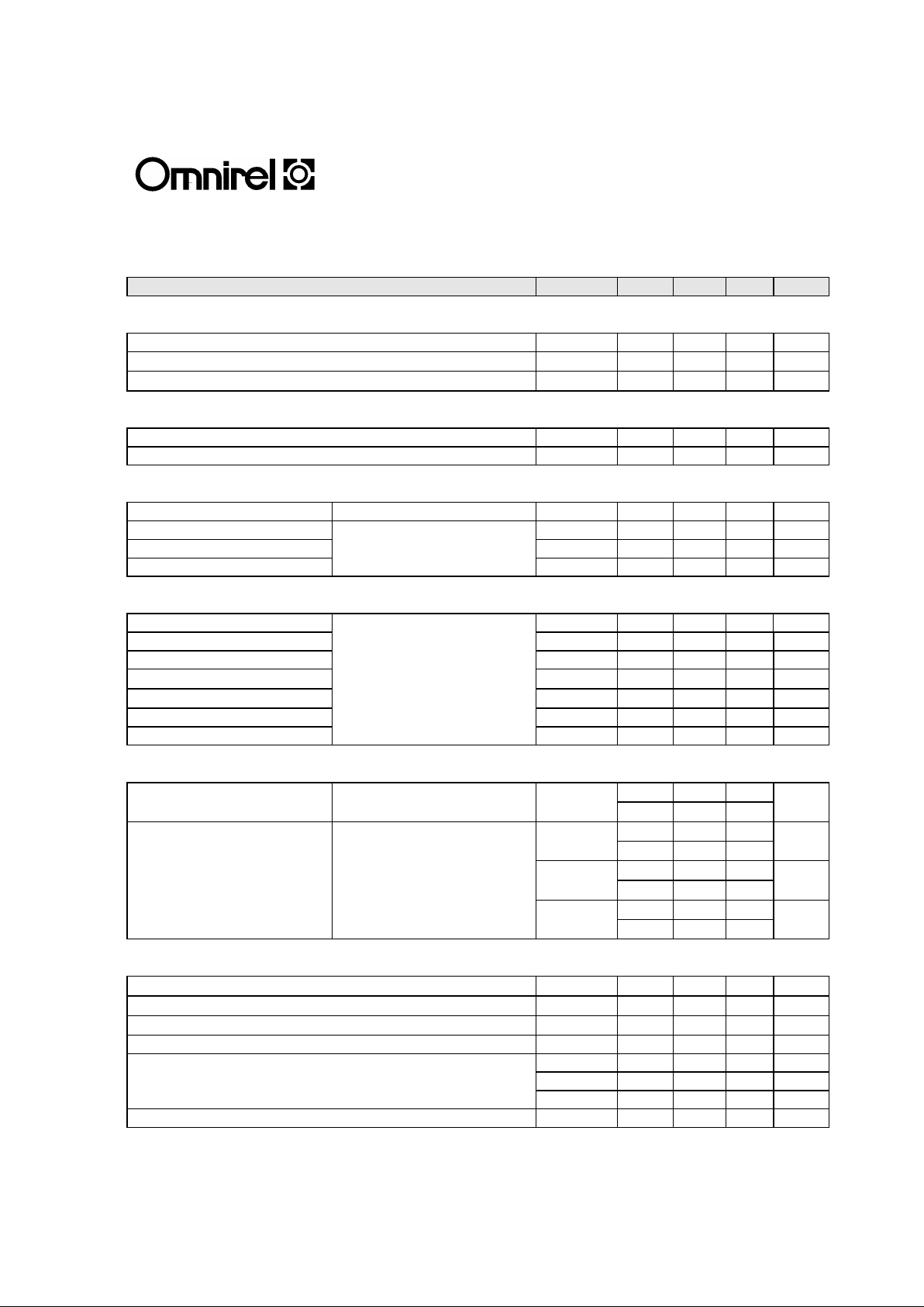
ELECTRICAL CHARACTERISTICS: OM300L60CMD (Tc= 25°°C unless otherwise specified)
Characteristic Symbol Min. Typ. Max Unit
OFF CHARACTERISTICS
Collector Emitter Breakdown Voltage, VCE=0V VCES 600 V
Zero Gate Voltage Drain Current, VGE=0, VCE =600V ICES 25
µA
Gate Emitter Leakage Current, VGE=+/-15V, VCE=0V IGES 2
µA
ON CHARACTERISTICS
Gate Threshold Voltage, VCE=VGE, IC=6mA VGE(TH) 4.5 6.5 V
Collector Emitter Saturation Voltage, VGE=15V, IC=300A VCE(SAT) 2.4 2.7 V
DYNAMIC CHARACTERISTICS
Fwd. Transconductance VCE=5V, IC=300A gfs 42 S
Input Capacitance VGE=0 Cies
pF
Output Capacitance VCE=25V Coes 9500 pF
Rev. Transfer Capacitance f=1.0MHz Cres
pF
SWITCHING INDUCTIVE LOAD CHARACTERISTICS
Turn-On Delay Time t(on) 800
nS
Rise Time VCC= 300V, IC=300A tr 400 800 nS
Turn-on Losses Eon mJ
VGE=+15/-10V, RG=6.8Ω
Turn-off Delay Time
L=100µH,Tj=125°C
td(off) 800
nS
Fall Time tf 350 800 nS
Turn-off Losses Eoff mJ
DIODE CHARACTERISTICS
Maximum Forward Voltage
IF=300A, Tj=25°C
VF 1.5 2.0 V
Tj=125°C
VR=300V, Tj=25°C
Qrr 8
µC
Reverse Recovery
IF=300A, Tj=125°C
20
Characteristics
dI/dt=-1500A/µS Tj=25°C
Irr 50 A
Tj=125°C
80
Tj=25°C
trr 160 nS
Tj=125°C
220
THERMAL CHARACTERISTICS
Thermal Resistance, Junction to Case (Per IGBT) RthJC 0.11
°C/W
Thermal Resistance, Junction to Case (Per Diode) RthJC 0.14
°C/W
Maximum Junction Temperature TjMAX 150
°C
Isolation Voltage Vis
RMS
2500 V
Screw Torque Mounting - 15 20 in-lb
Screw Torque (M6) Terminals - 10 12 in-lb
Screw Torque (M3) Terminals - 6 8 in-lb
Module Weight - 400 Grams
Page 2
205 Crawford St. Leominster, MA 01453 (978)534-5776 Fax(978)537-4246
12/08/98 Rev. 03 2
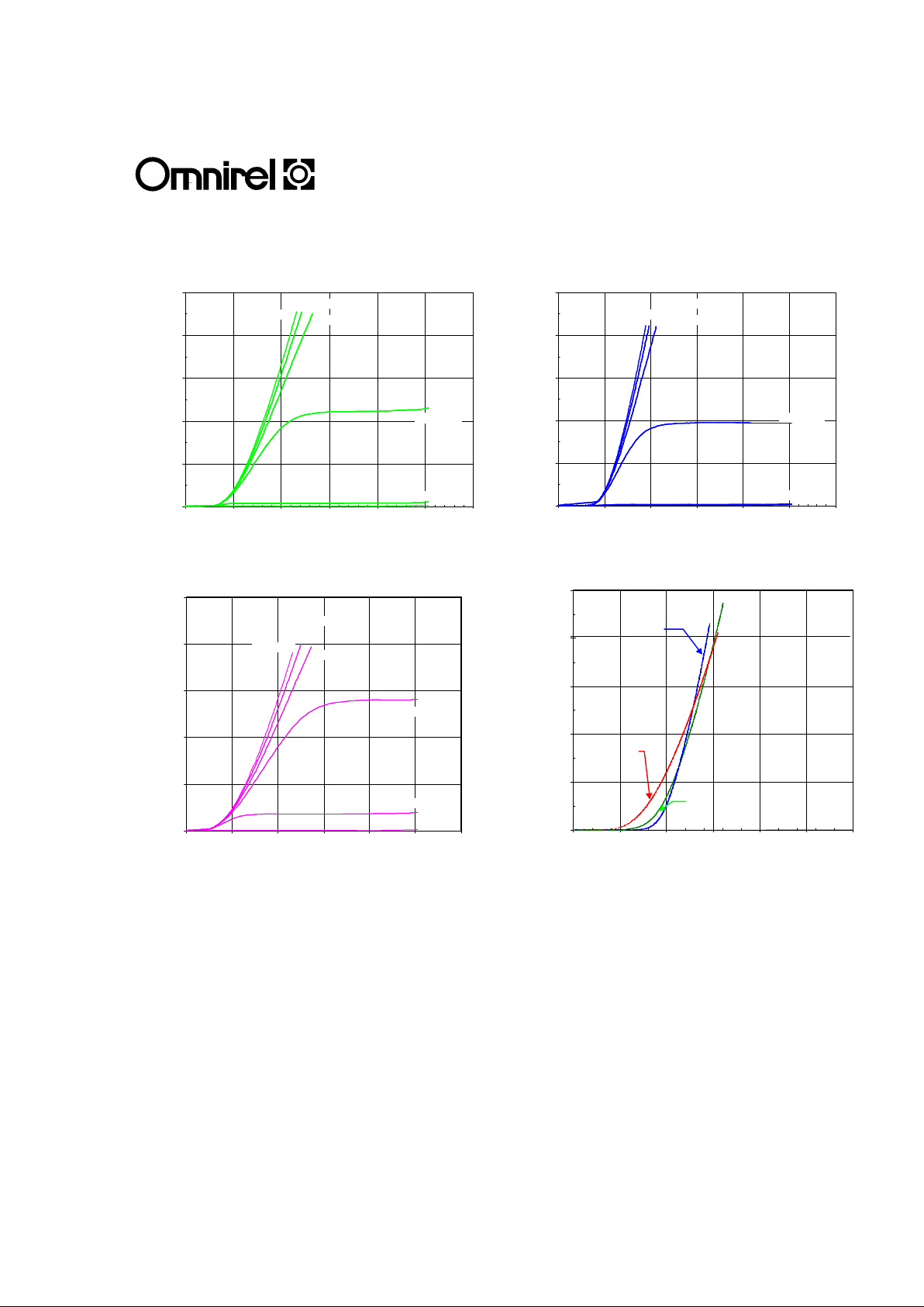
OM300L60CMD
IGBT Collector current vs. Collector-emitter voltage
Tj=25°C
0
100
200
300
400
500
0 1 2 3 4 5 6
VCE (V)
IC (A)
Vge = 11V
Vge = 15V
Vge = 9V
Vge = 13V
Vge = 7V
IGBT Collector Current vs. Collector-emitter Voltage
Tj=-55°C
0
100
200
300
400
500
0 1 2 3 4 5 6
VCE (V)
IC (A)
Vge = 11V
Vge = 15V
Vge = 9V
Vge = 13V
Vge = 7V
IGBT Collector Current vs. Collector-emitter voltage
Tj=125°C
0
100
200
300
400
500
0 1 2 3 4 5 6
Vce(V)
Ic(A)
Vge = 15V
Vge = 13V
Vge = 11V
Vge = 9V
Vge =7V
Diode Forward Current vs. Forward voltage
Vge =0V
0
100
200
300
400
500
0 0.5 1 1.5 2 2.5 3
Vf (V)
If (A)
Tj=125°C
Tj=-55°C
Tj=25°C
Page 3

205 Crawford St. Leominster, MA 01453 (978)534-5776 Fax(978)537-4246
12/08/98 Rev. 03 3
OM300L60CMD
MECHANICAL OUTLINE
C2E1
E2
C1
G2
E2
E1
G1
EQUIVALENT CIRCUIT
C1
E2
C2E1
E1
G1
G2
E2
 Loading...