

Page 1
Evaluation board available.
NEXSEM
HIGH SPEED 12V SYNCHRONOUS MOSFET DRIVER
DESCRIPTION
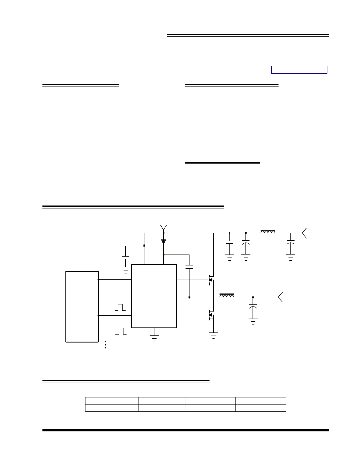
The NX3202 is a high frequency MOSFET driver designed
to drive two N-Channel MOSFETs in a synchronous rectified Step Down(BUCK) regulator topology. This driver
combined with other NEXSEM controllers such as NX2511
or NX2517 2 to 4 phase controller ICs makes a high
efficiency high performance Multiphase regulator designed for latest Microprocessor Vcore power as well as
other high current regulator applications. The IC is powered by a single 12V supply and its low resistance drivers minimizes switching losses for high frequency applications using high gate capacitance MOSFETs. The
NX3202 features 0.8 ohm sink resistance for the lower
gate driver capable of holding the lower MOSFET gate
off during SW node fast dv/dt rise time, preventing shoot
through power loss.
NX3202
PRELIMINARY DATA SHEET
Pb Free Product
FEATURES
n Bus voltage operation from 4V to 26V
n 12V High side and Low side drive capability
n High Peak Current Drive Capability
n High Frequency Operating Range
n Minimal Propagation Delay
n Non-overlap Adaptive Control
n Output disable(ODB) signal turns both outputs
off
n Pb-free and RoHS compliant
APPLICATIONS
n Desktop and Notebook Microprocessor Vcore
regulator applications
n High Current Multiphase Converter
n High Efficiency / High Current Graphic Vcore
Multiphase
PWM
Controller
(eg.NX2511)
START
PWM1
PWM2
+12V
D1
C3
1uF
3
2
ODB
IN
4
Vcc BST
1
8
Hdrv
7
SW
NX3202
5
Ldrv
C6
0.1uF
Gnd
6
Figure1 - Typical application of NX3202
TYPICAL APPLICATION
L2 1uH
C5
1uF
M1
L1 1.5uH 1.5mohm
M2
Cin
2200uF
470uF
Co
8 x 1500uF,11mohm
C4
Vout
@VCORE
+12V
Rev. 1.1
04/24/06
ORDERING INFORMATION
Device Temperature Package Pb-Free
NX3202CSTR 0 to 70oC SOIC-8L Yes
www.nexsem.com
1
Page 2
NEXSEM
CW
θ≈130/
PARAMETERS
SYM
TEST CONDITIONS
MIN
TYP
MAX
UNITS
CL=0
CL=3nF
Vcc Quiescent Current
ODB
ODB Threshold (Low)
ODB(L)
0.8
V
ODB=0V
IN=0V
Supply
Vcc Quiescent Current Operating
NX3202
ABSOLUTE MAXIMUM RATINGS
Vcc to GND & BST to SW Voltage ................... 16V
BST to GND Voltage ...................................... 35V
SW to GND Voltage ...................................... 35V
ODB & IN to GND Voltage ............................... 16V
Storage Temperature Range ............................. -65oC to 150oC
Operating Junction Temperature Range ............. -40oC to 125oC
Caution: Stresses above those listed in "ABSOLUTE MAXIMUM RATINGS", may cause permanent damage to
the device. This is a stress only rating and operation of the device at these or any other conditions above those
indicated in the operational sections of this specification is not implied.
PACKAGE INFORMATION
8-PIN PLASTIC SOIC (S)
o
8
HDrv
7
SW
6
GND
5
LDrv
BST
IN
ODB
VCC
JA
1
2
3
4
ELECTRICAL SPECIFICATIONS
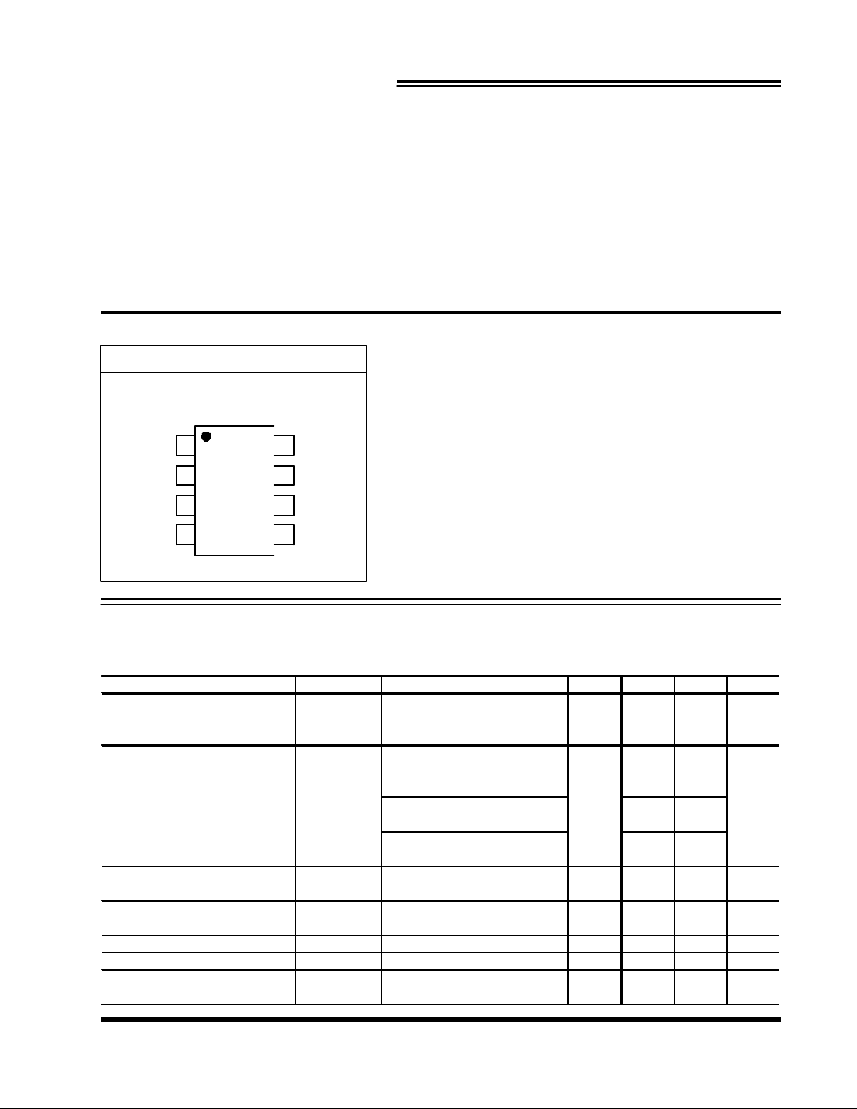
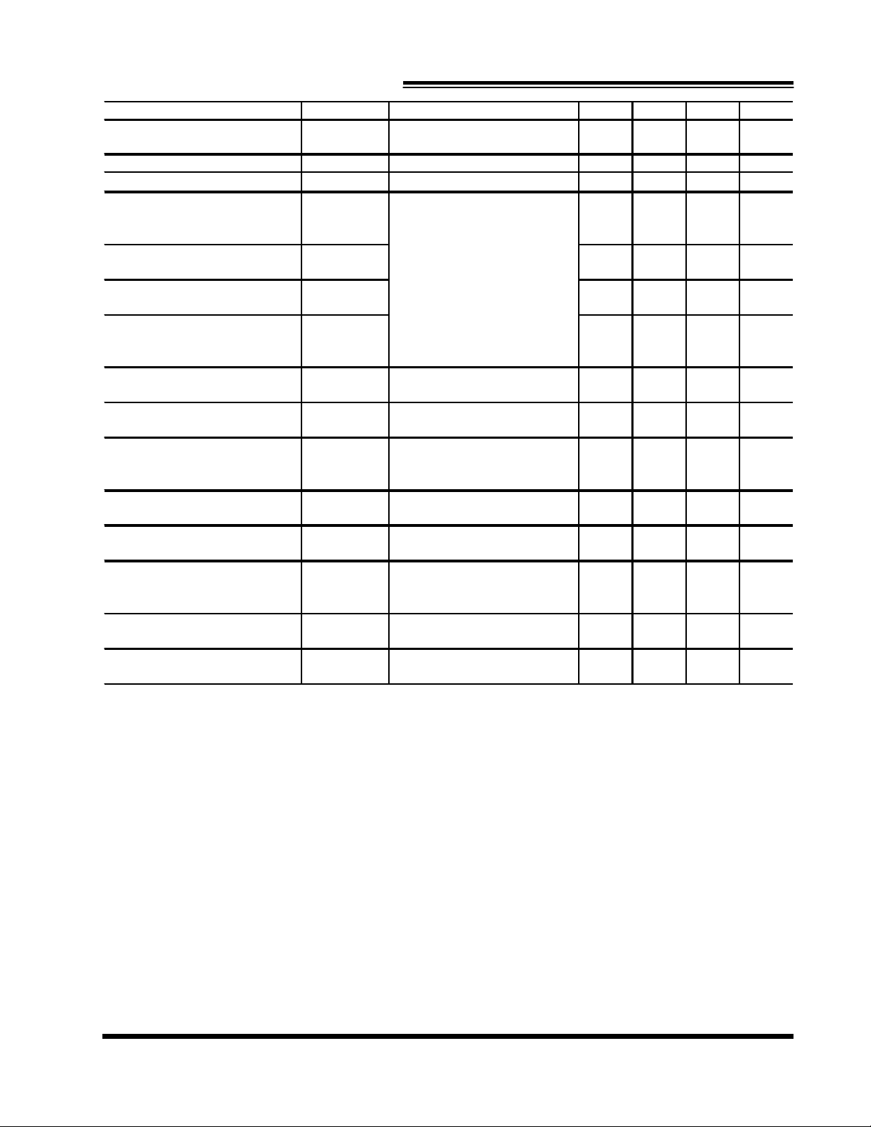
Unless otherwise specified, these specifications apply over VCC =BST= 12V, SW=GND=0V, ODB=VCC, and TA =
0 to 125oC. Typical values refer to TA = 25oC.
Vcc Supply
Under Volatge Lockout, VCC
Mode
UVLO, Vcc
Iq mA
Vcc ramping up 3
VBST=12V, IN=0V 1.6
V
Shutdown Mode
ODB Threshold (High) ODB(H) 2.4 V
ODB Current Ienb -2 2 uA
Propagation delay time Tprop 15 ns
Rev. 1.1
04/24/06
IN=Swch at 500Khz, 50% DC,
IN=Swch at 200Khz, 50% DC,
Iqsd
www.nexsem.com
3.2
17
1.2
mA
2
Page 3
NEXSEM
PARAMETERS
SYM
TEST CONDITIONS
MIN
TYP
MAX
UNITS
Input voltage High
IN (H)
2.4
V
bias-ODB
Low Side Driver(CL=3300pF)
Current
Current
Current
Current
High, 10% to 10%
HI
NX3202
IN
Input Voltage low IN(L) 0.8 V
Input Current I
High Side driver(CL=3300pF)
Output Impedance, Sourcing
R
source
(Hdrv)
VBST-VSW=12V
-2 2 uA
1.7
Ohm
Output Impedance , Sinking
Rise Time THDrv(Rise) 40
Fall Time THDrv(Fall) 20 ns
Deadband Time Tdead(L to H) 75 ns
Propagation Delay Tdelay(H) 55 ns
Output Impedance, Sourcing
Output Impedance , Sinking
Rise Time TLDrv(Rise) 40 ns
Fall Time TLDrv(Fall) 20 ns
Deadband Time Tdead(H to L) 30 ns
Propagation Delay Tdelay(L) 65 ns
R
(Hdrv) 0.7 Ohm
sink
LDRV going Low to HDrv
going High, 10% to 10%
IN going HI to LDRV going
Low
R
(Ldrv) 1.7 Ohm
source
R
(Ldrv) 0.7 Ohm
sink
10% to 90%
90% to 10%
SW going Low to LDRV going
IN going Low to LDRV going
ns
Rev. 1.1
04/24/06
www.nexsem.com
3
Page 4
NEXSEM
PIN DESCRIPTIONS
Pin# Pin Symbol Pin Description
1 BST Bootstrap Pin. A capacitor is connected between BST and SW pins to generate the
floating bootstrap voltage for High-side Driver. The capacitor value is typically between
0.1uf to 1uF.
2 IN PWM input signal to the MOSFET drivers.
3 ODB Output disable pin. When high the internal circuitry is enabled. When low both high side
and low side drivers are turned off.
4 VCC Biasing supply both for the IC and lowside driver, a minimum of 1uF ceramic cap should
be connected between this pin and PGND.
5 LDRV Output driver for low side MOSFET.
6 GND Power ground.
7 SW Switching point, this pin connects to the junction of external high-side and low-side
MOSFETs.
8 HDRV Output drive for high-side MOSFET.
NX3202
Rev. 1.1
04/24/06
www.nexsem.com
4
Page 5
NEXSEM
NX3202
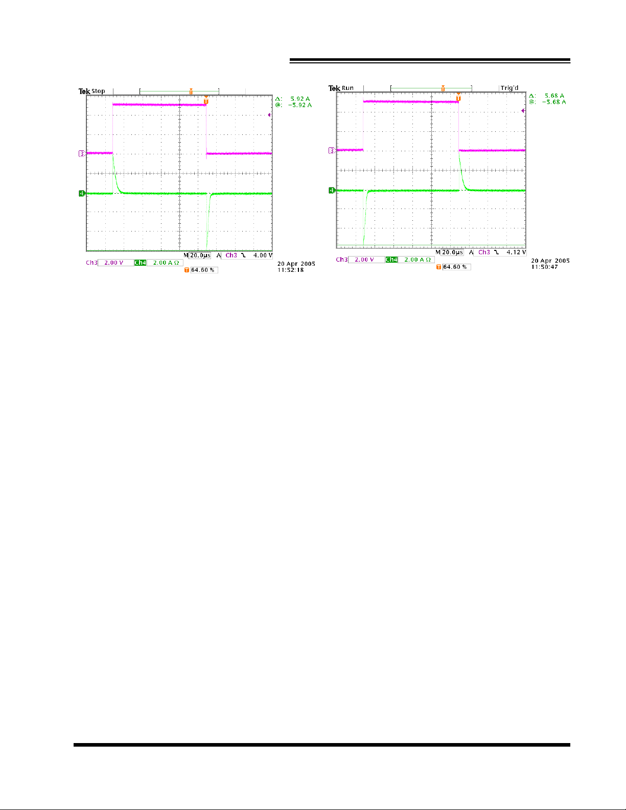
Figure 2 - Hdrv peak current
Figure 3 - Ldrv peak current
Rev. 1.1
04/24/06
www.nexsem.com
5
 Loading...