

Page 1
NWK954
QUAD FAST ETHERNET REPEATER
PRELIMINARY INFORMATION
Supersedes January 1998 version, DS4842 - 1.1 DS4842-2.1 April 1998
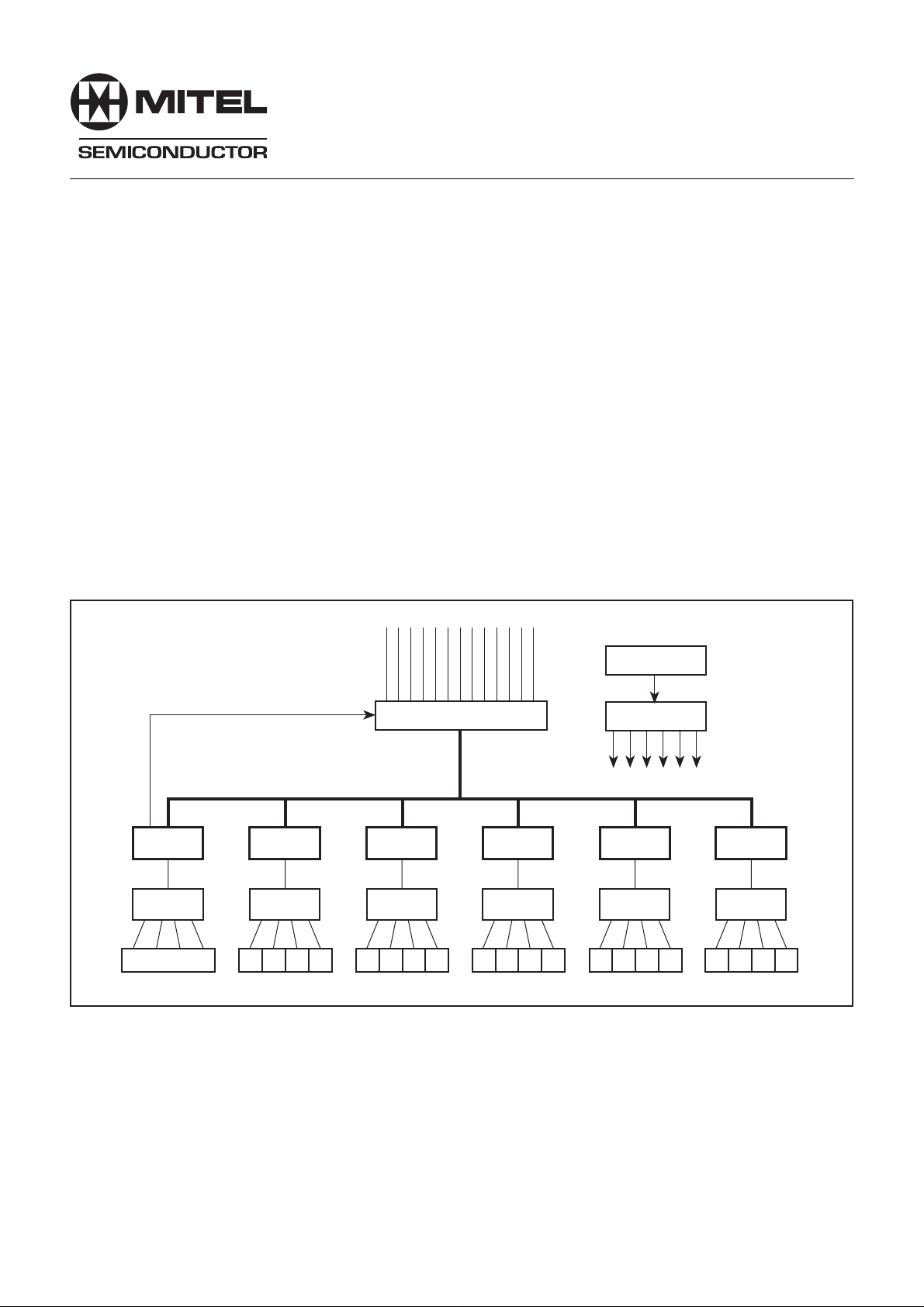
The NWK954 is a fully integrated, unmanaged, 4-port Fast
Ethernet Repeater conforming to the IEEE 802.3 100BASE-TX
Standard. The device integrates the 802.3 Repeater functions
with four 100BASE-TX PHY modules, enabling direct connection
to the isolation transformers with no additional PHY components.
It has built-in LED drivers for display of port activity and
network utilization. There is a local expansion port which allows
up to six NWK954s to be cascaded to form a 24-port repeater
with no additional components.
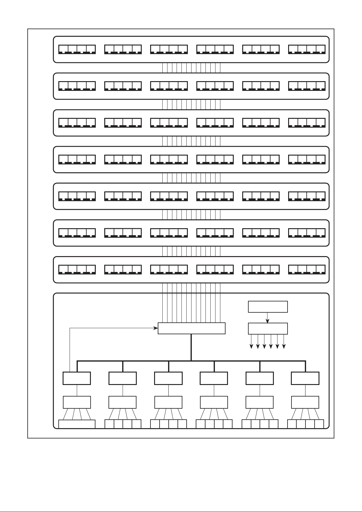
With the addition of simple backplane driver/receivers, up to
eight 24-port repeaters can be stacked.
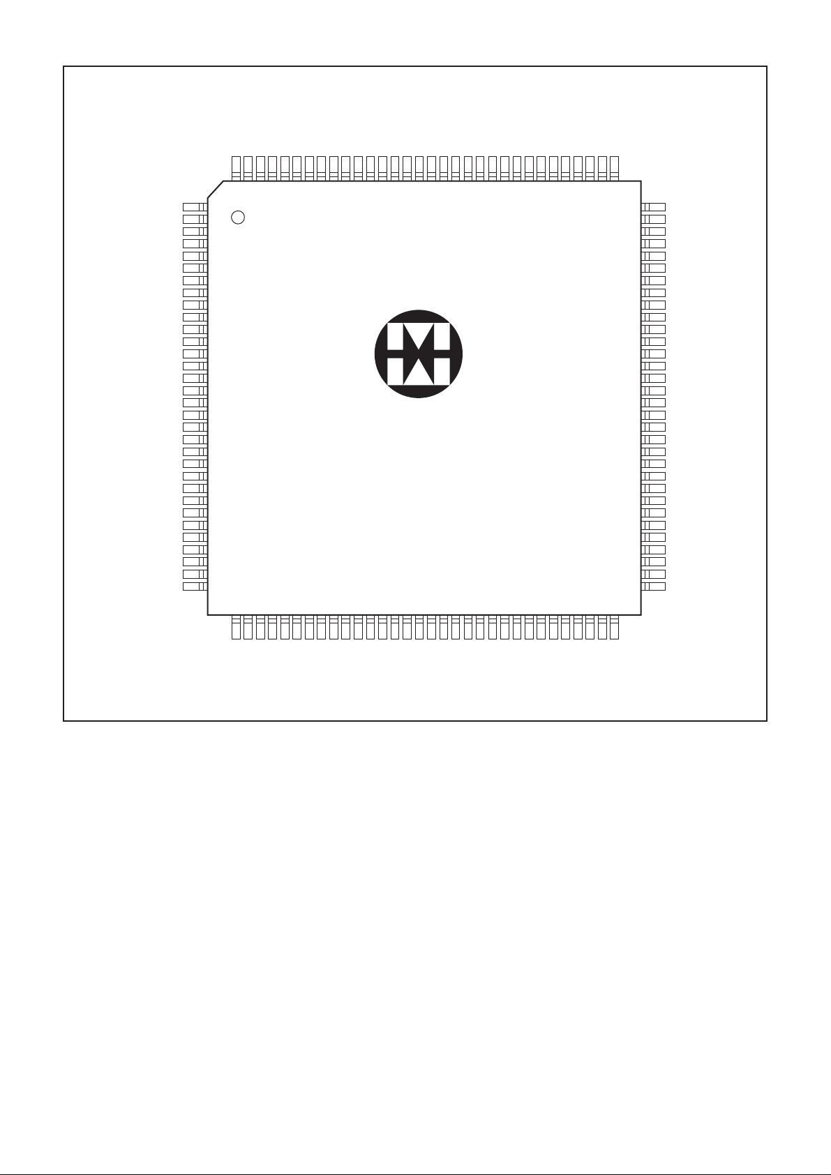
The NWK954 is supplied in a 128-pin PQFP and interfaces
to the twisted pair media through 1:1 isolation transformers.
ORDERING INFORMATION
NWK954D/CG/GH1N
FEATURES
■ Compliant with IEEE 802.3 100BASE-TX Repeater
Unit Specification
■ Incorporates four IEEE 802.3 Compliant 100BASE-TX
Ports
■ Local Expansion Port for Cascading to 24 Ports
■ Stackable Backplane for Expansion up to 192 Ports
■ Link/Activity LED and Receive Error LED for each Port
■ Collision LED
■ Five LED Network Utilization Display
■ Base Line Wander Correction
■ Power Saving on Unused Ports
■ Driven from a Single 25MHz Clock
■ Single 5V supply
■ Low Power CMOS Technology
■ 128-pin PQFP package
OSCILLATOR
BACKPLANE CONTROLS
NWK954
QUAD
MAGNETICS
QUAD RJ45
LOCAL EXPANSION BUS
NWK954
QUAD
MAGNETICS
BACKPLANE BUFFERS
NWK954
QUAD
MAGNETICS
Fig. 1 System block diagram
NWK954
QUAD
MAGNETICS
CLOCK DRIVERS
NWK954
QUAD
MAGNETICS
NWK954
QUAD
MAGNETICS
Page 2
NWK954
Hub 7
Hub 6
Hub 5
Hub 4
Hub 3
Hub 2
Hub 1
Hub 0
BACKPLANE CONTROLS
LOCAL EXPANSION BUS
BACKPLANE BUFFERS
OSCILLATOR
CLOCK DRIVERS
NWK954
QUAD
MAGNETICS
QUAD RJ45
NWK954
QUAD
MAGNETICS
NWK954
QUAD
MAGNETICS
NWK954
QUAD
MAGNETICS
NWK954
QUAD
MAGNETICS
NWK954
QUAD
MAGNETICS
Fig. 2 192-port stacked repeater
2
Page 3
IRD3
IRD2
DIGGND2
DIGVDD2
P0_RXLED_N
P0_ERLED_N
P1_RXLED_N
P1_ERLED_N
P2_RXLED_N
P2_ERLED_N
P3_RXLED_N
P3_ERLED_N
ACTLED_N4
ACTLED_N3
ACTLED_N2
ACTLED_N1
ACTLED_N0
DIGGND3
DIGVDD3
COLLED_N
BPDOE_N
BPDIE_N
BPCOLOE_N
BPACTOUT_N
BPCOLIN_N
BPACTIN_N1
BPACTIN_N2
BPACTIN_N3
DIGGND4
DIGVDD4
IRD1
NWK954
IRD0
IRD4
LACTOUT_N
DIGVDD1
DIGGND1
RESET_N
LACTIN_N1
LACTIN_N2
LACTIN_N3
LACTIN_N4
LACTIN_N5
TDC
TDIO
TA4
TA3
TA2
SUBVDD1
P0_RXGND3
P0_RXVDD3
P0_RXVDD2
P0_RXGND2
P0_RXGND1
P0_RXVDD1
P0_RXIN
P0_RXIP
P0_TXVDD3
P0_TXGND3
P0_TXREF
P0_TXGND2
P0_TXVDD2
P0_TXON
P0_TXOP
P0_GND1
119
118
117
116
128
127
126
125
124
123
122
121
1
2
3
4
5
6
7
8
9
10
11
12
13
14
15
16
17
18
19
20
21
22
23
24
25
26
27
28
29
30
31
32
33343536373839404142434445464748495051525354555657585960516263
120
115
NWK954
111
114
113
112
110
109
108
107
106
105
104
103
102
101
100
999897
96
95
94
93
92
91
90
89
88
87
86
85
84
83
82
81
80
79
78
77
76
75
74
73
72
71
70
69
68
67
66
65
64
BPCLK
BPCOL_N
DIGGND5
DIGVDD5
BPACTIN_N4
BPACTIN_N5
BPACTIN_N6
BPACTIN_N7
PSEN0
PSEN1
TXCLKIN
DIGGND6
DIGVDD6
VREFGND
VREFVDD
SUBVDD2
P3_RXGND3
P3_RXVDD3
P3_RXVDD2
P3_RXGND2
P3_RXGND1
P3–RXVDD1
P3_RXIN
P3_RXIP
P3_TXVDD3
P3_TXGND3
P3_TXREF
P3_TXGND2
P3_TXVDD2
P3_TXON
P3_TXOP
P3_TXGND1
P1_RXIP
P1_TXOP
P1_TXON
P1_TXVDD2
P1_TXGND1
P1_TXREF
P1_TXGND2
P1_RXIN
P1_TXVDD3
P1_TXGND3
P1_RXVDD1
P1_RXGND1
P1_RXGND2
Fig. 3 Pin connections – top view
FUNCTIONAL DESCRIPTION
Overvlew
The NWK954 is a mixed-signal CMOS device which
integrates all of the functions required for an unmanaged 4port 100BASE TX repeater as defined in the IEEE 802.3
Standard. The device incorporates all of the necessary
100BASE-TX PHY functions to allow direct interfacing to a
quad 1:1 magnetics module with a modest number of external
passive components. The built-in expansion port allows
cascading of up to 6 NWK954s to build a 24-port repeater
with no additional components and also allows stacking of
up to eight 24-port repeaters with the addition of simple
backplane driver/receiver components. The operating status
of the device is indicated on 14 outputs designed to directly
drive LEDs. This high level of integration combined with low
power consumption and low pin count offers an efficient and
low cost solution for Fast Ethernet unmanaged repeater design.
P2_RXIP
P1_RXVDD2
P1_RXVDD3
P1_RXGND3
P2_RXGND3
P2_RXVDD3
P2_RXVDD2
P2_RXGND2
P2_RXGND1
P2_RXIN
P2_TXVDD3
P2_RXVDD1
P2_TXREF
P2_TXGND3
P2_TXOP
P2_TXON
P2_TXVDD2
P2_TXGND2
P2_TXGND1
Compliance with Standards
The NWK954 is designed for compliance with the IEEE 802.3
Standard, Clause 24 (100BASE-X PCS and PMA), Clause 25
(100BASE-TX PMD) and Clause 27 (Repeater for 100Mb/s
Baseband Networks). Clause 25 references the FDDI twisted
pair PMD Standard, henceforth referred to as TP-PMD.
Compatibility With Other Devices
The NWK954 is designed to connect directly to 5 other
NWK954 devices using the expansion bus. The Expansion Port
is identical to that used on the NWK950 Repeater Controller.
The Expansion Port may be connected to a backplane through
external driver/receivers. The backplane specification is identical
to that used by the NWK950, so repeaters using the NWK950
may be stacked with repeaters using the NWK954.
GP128
3
Page 4
NWK954
LACTOUT_N
BPACTOUT_N
BPACTIN_ N [7:1]
BPCOLIN_N
BPCOLOE_N
ACTLED_N [4:0]
P0_RXLED_N
P0_ERLED_N
P1_RXLED_N
P1_ERLED_N
P2_RXLED_N
P2_ERLED_N
P3_RXLED_N
P3_ERLED_N
IRD [4:0]
LACTIN_N
BPDIE_N
BPDOE_N
BPCLK
BPCOL_N
COLLED_N
EXPANSION
PORT
LED
DRIVERS
REPEATER
CONTROLLER
PORT 0
TRANSCEIVER
PORT 1
TRANSCEIVER
PORT 2
TRANSCEIVER
PORT 3
TRANSCEIVER
P0_TXOP
P0_TXON
P0_TXREF
P0_RXIP
P0_RXIN
P1_TXOP
P1_TXON
P1_TXREF
P1_RXIP
P1_RXIN
P2_TXOP
P2_TXON
P2_TXREF
P2_RXIP
P2_RXIN
P3_TXOP
P3_TXON
P3_TXREF
P3_RXIP
P3_RXIN
VOLTAGE
REFERENCE
TX DRIVER
RX SIGNAL
DETECT
TRANSCEIVER
CONTROL
SCRAMBLER
DESCRAMBLER
LINE
MONITOR
SIPO AND
DECODER
POWER-ON
RESET
125MHz
SYNTHESIZER
RESET_N
CLOCK
RECOVERY
TA [4:2]
TXCLKIN
PSEN [1:0]
PISO
AND
ENCODER
EQUALIZER
AND BLW
CORRECTION
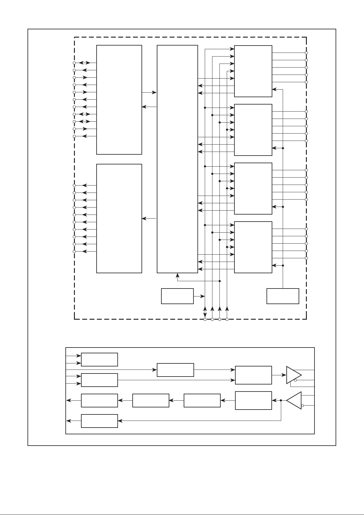
Port [3:0] transceiver details
Fig. 4 NWK954 block diagram
4
Page 5
Basic Repeater Function
The Repeater Controller monitors activity on the 4 twisted
pair ports and on the Expansion Port. When a packet is received
on one of the twisted pair ports it is forwarded to the other 3
twisted pair ports and to the Expansion Port. When a packet is
received on the Expansion Port it is forwarded to all 4 twisted
pair ports. When receive activity is detected on 2 or more ports
the Repeater Controller will send the jam signal to all twisted
pair ports for the duration of all activity associated with the
collision event.
BPACTIN_ N [7:1]
5
LACTIN_N [5:1]
LACTOUT_N
BPCOLIN_N
BPCOL_N
BPCLK
5
IRD [4:0]
NWK954
TXCLKIN
Jabber Protection
The Repeater Controller provides receive jabber protection
to ensure that the network is not disrupted by excessively long
data streams. If a received data stream exceeds 65,536 bit times
then the receiving port will be shutdown. In the shutdown state
data received on the faulty port is ignored and packets received
from other ports are not transmitted to the faulty port. A port will
recover from the shutdown state when the incoming data stream
ends or if the device is reset.
Auto-Partition Function
The auto-partition function prevents faulty behaviour on a
network segment from disrupting the entire network. The
Repeater Controller counts consecutive collisions on each port
and will partition a port that causes more than 60 consecutive
collisions. In the partitioned state, packets received on the faulty
port will be ignored but packets received from other ports will
continue to be transmitted to the faulty port. The port will recover
from the partitioned state when valid activity is detected on the
port or if the device is reset.
Carrier Integrity Monitor
The Repeater Controller detects false carrier events on all
ports. A false carrier is defined as receive activity that does not
commence with the correct start-of-packet sequence. When a
false carrier event is detected, the Repeater Controller will
transmit the jam signal on all ports for the duration of the false
carrier event provided it does not exceed 450-500 bit times.
After this time the port will be isolated and the jam signal will
cease. The NWK954 will also isolate a port that suffers 2
successive false carrier events. In the isolated state, packets
received from the faulty port are ignored and packets received
from other ports are not transmitted to the faulty port. A port will
recover from the isolated state when a valid inter-packet gap is
detected and is followed by either a valid packet exceeding 450500 bit times or by an idle sequence exceeding 33000 (±25%)
bit times.
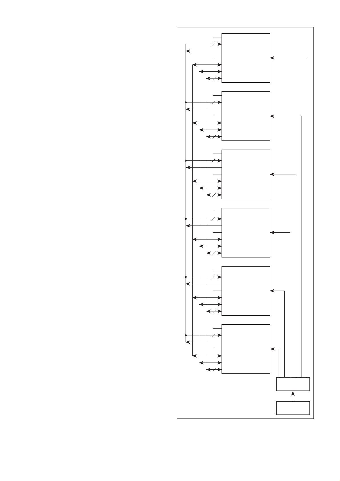
Expansion Port
The Expansion Port allows up to 6 NWK954s to be cascaded.
This allows a 24-port hub to be built with no additional external
components. The Expansion Port includes a 5-bit parallel
bidirectional data bus (IRD) which carries unscrambled symbol data
and a 25MHz sampling clock (BPCLK). Each NWK954 indicates
receive activity on any of its 4 twisted pair ports by asserting the
local activity output (LACTOUT_N). The LACTOUT_N signals from
each NWK954 connect to the local activity inputs (LACTIN_N) of all
the other cascaded NWK954s.
When a collision occurs between 2 twisted pair ports on an
NWK954, the event is communicated to other cascaded NWK954s
by asserting the collision signal (BPCOL_N). This instructs all
cascaded NWK954s to transmit the jam signal for the duration of
the collision event. BPCOL_N is also asserted when a collision occurs
between 2 twisted pair ports on different NWK954s.
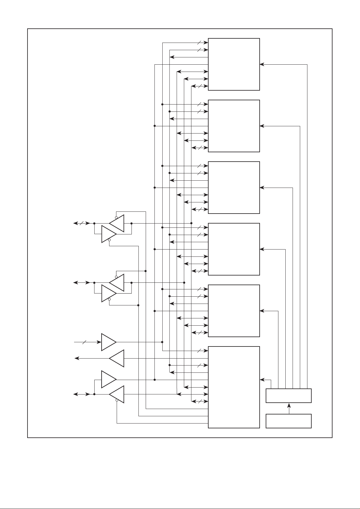
Backplane
The Expansion Port allows hubs to be stacked via a backplane
bus. This requires the addition of some simple external driver/
receivers. The functional requirement for these components is
illustrated in Fig. 6. Contact Mitel for full details of recommended
components.
BPACTIN_ N [7:1]
5
LACTIN_N [5:1]
LACTOUT_N
BPCOLIN_N
BPCOL_N
BPCLK
5
IRD [4:0]
BPACTIN_ N [7:1]
5
LACTIN_N [5:1]
LACTOUT_N
BPCOLIN_N
BPCOL_N
BPCLK
5
IRD [4:0]
BPACTIN_ N [7:1]
5
LACTIN_N [5:1]
LACTOUT_N
BPCOLIN_N
BPCOL_N
BPCLK
5
IRD [4:0]
BPACTIN_ N [7:1]
5
LACTIN_N [5:1]
LACTOUT_N
BPCOLIN_N
BPCOL_N
BPCLK
5
IRD [4:0]
BPACTIN_ N [7:1]
5
LACTIN_N [5:1]
LACTOUT_N
BPCOLIN_N
BPCOL_N
BPCLK
5
IRD [4:0]
TXCLKIN
TXCLKIN
TXCLKIN
TXCLKIN
TXCLKIN
Fig. 5 Cascaded NWK954s
CLOCK
DRIVER
25MHz
OSCILLATOR
5
Page 6
NWK954
7
BPACTIN_ N [7:1]
5
LACTIN_N [5:1]
LACTOUT_N
BPCOLIN_N
BPCOL_N
BPCLK
5
IRD [4:0]
7
BPACTIN_ N [7:1]
5
LACTIN_N [5:1]
LACTOUT_N
BPCOLIN_N
BPCOL_N
BPCLK
5
IRD [4:0]
7
BPACTIN_ N [7:1]
5
LACTIN_N [5:1]
LACTOUT_N
BPCOLIN_N
BPCOL_N
BPCLK
5
IRD [4:0]
TXCLKIN
TXCLKIN
TXCLKIN
BACKPLANE
DATA
BACKPLANE
CLOCK
BACKPLANE
ACTIVITY
BACKPLANE
COLLISION
5
7
7
BPACTIN_ N [7:1]
5
LACTIN_N [5:1]
LACTOUT_N
BPCOLIN_N
BPCOL_N
BPCLK
5
IRD [4:0]
7
BPACTIN_ N [7:1]
5
LACTIN_N [5:1]
LACTOUT_N
BPCOLIN_N
BPCOL_N
BPCLK
5
IRD [4:0]
7
BPACTIN_ N [7:1]
BPACTOUT_N
5
LACTIN_N [5:1]
LACTOUT_N
BPCOLIN_N
BPCLK
BPCOL_N
5
IRD [4:0]
BPDOE_N
BPDIE_N
BPCOLOE_N
TXCLKIN
TXCLKIN
TXCLKIN
CLOCK
DRIVER
25MHz
OSCILLATOR
Fig. 6 External backplane drivers/receivers
6
Page 7

NWK954
The IRD bus in each hub is connected to the 5-bit backplane
bus via a bidirectional buffer . This allows data to be driven from
any hub to all other hubs in the stack. The bidirectional buffer is
controlled by 2 control signals (BPDOE_N and BPDIE_N) which
can be taken from any one of the NWK954 devices in the hub.
BPDOE_N and BPDIE_N default to being active low but can be
independently changed to active high by the addition of an
external pull-down resistor, as shown in Fig.7. This resistor is
sensed during RESET_N = 0.
Data transfers on the backplane are synchronous to the
backplane clock. The backplane clock is supplied by whichever
hub supplies the data. When receiving data from the backplane,
the backplane clock is enabled onto the local BPCLK signal by
BPDIE_N. BPCLK connects to all NWK954s in the hub. When
a hub supplies data to the backplane, BPCLK is driven locally
and is enabled onto the backplane by BPDOE_N.
Each hub in a stack indicates receive activity on any of its
twisted pair ports by asserting the backplane activity output
(BP ACTOUT_N). BP ACT OUT_N can be taken from any one of
the NWK954s and drives one of the backplane activity signals
via an external buffer . The backplane supports up to 8 backplane
activity signals. The backplane activity signals from up to 7 other
hubs connect to the local BPACTIN_N signals which are input
to all NWK954s in the hub.
When a collision occurs between 2 twisted pair ports in a
hub, the event is communicated to other stacked hubs by
BPCOL_N which is enabled onto the backplane collision signal
by BPCOLOE_N. BPCOLOE_N defaults to being active low but
can be changed to active high by the addition of an external
pull-down resistor. This resistor is sensed during RESET_N=0.
BPCOL_N is also asserted when a collision occurs between
two twisted pair ports on different hubs. Collision events are
cormmunicated to all hubs through the BPCOLIN_N signal which
connects to all NWK954s in the hub.
LED Drivers
The NWK954 provides 2 LED drivers per port to indicate
port status (RXLED_N and ERLED_N), one LED driver to
indicate collisions (COLLED_N) and 5 LED drivers to indicate
network utilization (ACTLED_N). The LED drivers pull the output
pins low to turn the LEDs on. The LEDs are turned on or off for
a minimum of 40ms to ensure observability.
The port status LEDs indicate a variety of conditions and
provide rapid diagnosis of network faults,as shown in Table 1.
The network utilization LEDs are turned on at the thresholds
given in Table 2.
NWK954
Enable signal configured for active low operation
NWK954
10k
Enable signal configured for active high operation
Fig. 7 Polarity selection on BPDOE_N, BPDIE_N and
BPCOLOE_N
RXLED_N
Off
Off
On
Flash
On
Flash off
* In 802.3 a continuous signal of the required amplitude is sufficient to establish a link but no data can be passed to the
repeater controller until the descrambler has locked on to an idle pattern.
ERLED_N
Off
Flash
Off
Off
On
Flash on
No incoming signal
Incoming signal but no idle pattern recognized*
Link established, no incoming data packets
Link established, receiving data packets
Link established, but port partitioned due to excessive collisions
or port isolated due to false carriers
or port disabled due to jabber
Link established, false carrier or invalid data detected
Port status
Table 1
LED
ACTLED_N0
ACTLED_N1
ACTLED_N2
ACTLED_N3
ACTLED_N4
Network utilization
>1%
>12·5%
>25%
>50%
>60%
Table 2
7
Page 8

NWK954
100BASE-TX Receiver
The 100BASE-TX receiver recovers data from up to 140m
of Cat5 UTP cable. Received data is decoded and descrambled
and presented to the repeater controller as 5-bit symbols. The
Transceiver Controller sequences the start-up of the receiver
and does not allow data to be passed to the Repeater Controller
until the receiver is fully initialized and a link is established and
the descrambler is synchronized. After start-up the T ransceiver
Controller monitors the receiver and takes corrective action if a
fault is detected.
The Signal Detect continuously monitors the level on the
RXIP/RXIN differential input and indicates to the Transceiver
Controller when the signal amplitude is within the range of the
Equalizer. The acceptable level is considerably less than that
specified in the 802.3 Standard because the NWK954 receiver
is designed for recovery of signals from up to 140m of Cat5
UTP cable.
The Equalizer compensates for the signal attenuation and
distortion resulting from transmission down the cable and through
the isolation transformers. The Equalizer self- adjusts within 1ms
of Signal Detect indicating that the incoming signal is within the
acceptable range. Thereafter the Equalizer continuously adjusts
to small variations in signal level without corrupting the received
data.
The 100BASE-TX MLT3 code contains significant low
frequency components which are not passed through the
isolation transformers and cannot be restored by the Equalizer.
This leads to a phenomenon known as baseline wander (BLW)
which will cause an unacceptable increase in error rate if not
corrected. The NWK954 employs a quantized feedback
technique to restore the low frequency components and thus
maintain a very low error rate even when receiving signals such
as the ‘killer packet’ described in the TP-PMD specification.
The Clock Recovery circuit uses a Phase-Locked Loop (PLL)
to derive a sampling clock from the incoming signal. The
recovered clock runs at the symbol bit rate (nominally 125MHz)
and is used to clock the ML T3 decoder and the Serial-to-Parallel
converter (SIPO). The recovered clock is divided by 5 to generate
the receive clock which is used to strobe received data into the
Repeater Controller. The Transceiver Controller monitors
behaviour of the PLL and re-initializes the receiver if lock is lost.
The SIPO and Decoder convert the received signal from serial
ML T3 to 5-bit parallel NRZ.
The Link Monitor implements the 802.3 Link Monitor State
Machine which indicates when a sustained signal of appropriate
quality and amplitude is being received. This is the first stage in
establishing a link; no data can be passed to the Repeater
Controller until the Descrambler is synchronized to the incoming
signal. Descrambler synchronization is established during
reception of the idle pattern. After synchronization is established,
the Descrambler output is continuously monitored and the
Descrambler is re-synchronized if insufficient idle sequences
are detected.
100BASE-TX Transmitter
The 100BASE-TX transmitter generates a 125MHz transmit
clock and uses it to serialize and transmit the 5-bit symbol data
input from the Repeater Controller. The Transceiver Controller
sequences the start-up of the transmitter and does not allow
transmission onto the twisted pair until the transmitter is fully
initialized. After start-up the T ransceiver Controller monitors the
transmitter and takes corrective action if a fault is detected.
The Scrambler mixes the symbol data with a 2047-bit pseudorandom code, in accordance with the TP-PMD Standard. The
four Scramblers in the NWK954 are seeded with different values
based on the TA[4:2] input. When multiple NWK954s are
cascaded to make a hub, each NWK954 should have a unique
value on T A[4:2] to ensure that all of the Scramblers in the hub
are seeded with different values.
The 125MHz Synthesizer employs a phase-locked loop (PLL)
to generate a 125MHz timing reference from the 25MHz
reference clock. The Transceiver Controller monitors
behaviour of the PLL and re-initializes the Synthesizer if lock
is lost.
The PISO and Encoder take NRZ-coded symbols from
the Scrambler, and convert them to serial ML T3 for outputting
to the TX Driver. The PISO and Encoder do not operate until
the 125MHz Synthesizer is locked to the 25MHz reference.
This avoids transmission of spurious signals onto the twisted
pair.
The TX Driver outputs the differential signal onto the TXOP
and TXON pins. It operates with 1:1 magnetics to provide
impedance matching and amplification of the signal in
accordance with the 802.3 specifications. The transmit current
is governed by the current through the TXREF100 pin, which
must be grounded through a resistor as described in
Table 10.
Power Saving on unused ports
The NWK954 incorporates a feature that will automatically
shutdown the transceivers on unused ports. The shutdown
occurs if Signal Detect indicates that no signal has been received
for 2·5s. The transceiver is re-started when Signal Detect
indicates that an incoming signal has been detected. This feature
is intended to save power and reduce noise in unconnected
ports. In certain circumstances, such as in port-to-port links
between hubs, this feature should be suppressed by appropriate
setting of the PSEN [1:0] inputs, as shown in Table 3.
Initialization
The NWK954 incorporates a power-on reset circuit for selfinitialization on power-up. During power-on reset the open drain
RESET_N pin is driven low. It will not normally be necessary for
the user to drive RESET_N because the NWK954 is designed
to automatically recover from fault conditions; however, if
required, the user may initialize the device by pulsing RESET_N
low.
PSEN1
0
0
1
1
PSEN0
0
1
0
1
Power saving disabled on all ports
Power saving enabled on ports 1, 2 and 3, disabled on port 0
Power saving enabled on ports 0, 1 and 2, disabled on port 3
Power saving enabled on all ports
Function
Table 3 Power saving functions
8
Page 9

PIN DESCRIPTIONS
Active low signals are denoted by the _N suffix; all other signals are active high
Network Interface
NWK954
Signal
P0_RXIP
P0_RXIN
P0_TXOP
P0_TXON
P0_TXREF
P1_RXIP
P1_RXIN
P1_TXOP
P1_TXON
P1_TXREF
P2_RXIP
P2_RXIN
P2_TXOP
P2_TXON
P2_TXREF
P3_RXIP
P3_RXIN
P3_TXOP
P3_TXON
P3_TXREF
Pin no.
24
23
31
30
27
41
42
34
35
38
56
55
63
62
59
73
74
66
67
70
Type
Analog input
Analog input
Analog output
Analog output
Analog output
Analog input
Analog input
Analog output
Analog output
Analog output
Analog input
Analog input
Analog output
Analog output
Analog output
Analog input
Analog input
Analog output
Analog output
Analog output
Description
(1) Differential receive signal from port 0 magnetics
(2) Differential receive signal from port 0 magnetics
(1) Differential transmit signal to port 0 magnetics
(2) Differential transmit signal to port 0 magnetics
Port 0 transmitter current setting pin, grounded externally
(1) Differential receive signal from port 1 magnetics
(2) Differential receive signal from port 1 magnetics
(1) Differential transmit signal to port 1 magnetics
(2) Differential transmit signal to port 1 magnetics
Port 1 transmitter current setting pin, grounded extemally
(1) Differential receive signal from port 2 magnetics
(2) Differential receive signal from port 2 magnetics
(1) Differential transmit signal to port 2 magnetics
(2) Differential transmit signal to port 2 magnetics
Port 2 transmitter current setting pin, grounded extemally
(1) Differential receive signal from port 3 magnetics
(2) Differential receive signal from port 3 magnetics
(1) Differential transmit signal to port 3 magnetics
(2) Differential transmit signal to port 3 magnetics
Port 3 transmitter current setting pin, grounded extemally
Expansion Port
Signal
IRD4
IRD3
IRD2
IRD1
IRD0
LACTOUT_N
LACTIN_N5
LACTIN_N4
LACTIN_N3
LACTIN_N2
LACTIN_N1
BP ACT OUT_N
Pin no.
1
128
127
98
97
2
10
9
8
7
6
105
Type
High drive open
drain digital
output and digital
input with pull-up
High drive digital
output
Digital input,
no pull-up
Standard digital
output
Table 4
Description
Inter-repeater data. Transfers 5-bit symbol data between
NWK954s on the local expansion bus, and to/from the
backplane drivers. Transfers are synchronous to BPCLK.Require
external pull-ups for correct operation.
Local activity output. Indicates receive activity in this
NWK954. Connects to all other NWK954s on the local
expansion bus. Output changes asynchronously .
Local activity inputs. One input from each NWK954 on
the local expansion bus to indicate receive activity. Unused
inputs must be pulled high or connected directly to
DIGVDD. Inputs are sampled on on the rising edge of TXCLKIN.
Backplane activity output. Indicates receive activity on
any of the NWK954s on the local expansion bus. Drives
the backplane through an external driver. Only one of the
local NWK954s is required to drive this signal, the others
should be left unconnected. Output changes asynchronously.
Table 5
Continues…
9
Page 10

NWK954
Expansion Port (Continued)
Signal
BP ACTIN_N7
BP ACTIN_N6
BP ACTIN_N5
BP ACTIN_N4
BP ACTIN_N3
BP ACTIN_N2
BP ACTIN_N1
BPDIE_N
BPDOE_N
BPCLK
BPCOL_N
BPCOLIN_N
BPCOLOE_N
Pin no.
89
90
91
92
101
102
103
107
108
96
95
104
106
Type
Digital input,
no pull-up
Standard digital
output and digital
input with pull-up
Standard digital
output and digital
input with pull-up
High drive open
drain digital output
and digital input
with pull-up
High drive open
drain digital output
and digital input
with pull-up
Digital input,
no pull-up
Standard digital
output and digital
input with pull-up
Table 5 (continued)
Description
Backplane activity inputs. Indicate activity on up to 7
other hubs connected to the backplane. Received from the
backplane via external receivers. Each NWK954
connected to the local expansion bus receives all of these
backplane activity inputs. Unused inputs must be pulled
high or connected directly to DIGVDD. Inputs are sampled
on the rising edge of TXCLKIN.
Backplane data input enable. Enables the external
receivers that pass backplane data and clock onto the local
IRD[4:0] and BPCLK lines. Only one of the local NWK954s
is required to drive this signal, the others should be left
unconnected. This signal changes asynchronously .
Polarity defaults to active low but may be switched to
active high by adding an external 10kΩ pull-down.
Backplane data output enable. Enables the external
drivers that pass the local IRD[4:0] and BPCLK signals
onto the backplane. Output changes on the rising edge of
TXCLKIN. Only one of the local NWK954s is required to drive
this signal, the others should be left unconnected. Polarity
defaults to active low but may be switched to active high by
adding an external 10kΩ pull-down.
25MHz backplane clock. Data transitions on IRD[4:0] are
synchronised to this clock. When another hub in the stack
is sourcing data, this clock is received from the backplane
to all local NWK954s through an external receiver. When a
local NWK954 is sourcing data, BPCLK is supplied to the
backplane through an external driver. Requires external
pull-up for correct operation
Backplane collision. This signal may be driven by any of
the local NWK954s to indicate that a collision has been
detected, and is supplied to the backplane through an
external driver. Output transitions are synchronous to
the rising edge of TXCLKIN and the input is sampled on the
rising edge of TXCLKIN. Requires external pull-up for correct
operation.
Backplane collision input. Indicates that a collision has
been detected by any hub in the stack. Received from the
backplane via an external receiver. Connects to all local
NWK954s. Must be pulled high or connected directly to
DIGVDD if not used. Input is sampled on the falling edge of
TXCLKIN.
Backplane collision output enable. Enables the external
driver that passes BPCOL_N onto the backplane. Only one
of the local NWK954s is required to drive this signal, the
others should be left unconnected. Output changes on the
rising edge of TXCLKIN. Polarity defaults to active low but
may be switched to active high by adding an external 10kΩ
pull-down.
.
10
Page 11

LED Drivers
NWK954
Signal
COLLED_N
P0_RXLED_N
P1_RXLED_N
P2_RXLED_N
P3_RXLED_N
P0_ERLED_N
P1_ERLED_N
P2_ERLED_N
P3_ERLED_N
ACTLED_N4
ACTLED_N3
ACTLED_N2
ACTLED_N1
ACTLED_N0
Pin no.
109
124
122
120
118
123
121
119
117
116
115
114
113
112
Type
Standard
digital output
Standard
digital output
Standard
digital output
Standard
digital output
Standard
digital output
Standard
digital output
Standard
digital output
Standard
digital output
Standard
digital output
Standard
digital outputs
Description
Collision LED. Drives an LED to indicate that a collision
has occurred either locally or elsewhere in the stack.
Port 0 activity LED. Drives an LED to indicate link/activity
on port 0. The LED is turned on when a link is established
and flashes off when a packet is being received.
Port 1 activity LED. Drives an LED to indicate link/activity on
port 1. The LED is turned on when a link is established and
flashes off when a packet is being received.
Port 2 actlvlty LED. Drives an LED to indicate link/activity on
port 2. The LED is turned on when a link is established and
flashes off when a packet is being received.
Port 3 activlty LED. Drives an LED to indicate link/activity on
port 3. The LED is turned on when a link is established and
flashes off when a packet is being received.
Port 0 error LED. Drives an LED to indicate an error on
port 0. See the text for a full description.
Port 1 error LED. Drives an LED to indicate an error on
port 1. See the text for a full description.
Port 2 error LED. Drives an LED to indicate an error on
port 2. See the text for a full description.
Port 3 error LED. Drives an LED to indicate an error on
port 3. See the text for a full description.
Utilization LEDs. Drives 5 LEDs to indicate utilization of the
network segment. See the text for a full description.
Clocks and Controls
Signal
TXCLKIN
RESET_N
PSEN0
PSEN1
TA4
TA3
TA2
Pin no.
86
5
87
88
13
14
15
Type
Digital input
no pull-up
Open drain
digital output and
digital input,
no pull-up
Digital inputs
with pull-ups
Digital inputs,
no pull-ups
Table 6
Description
25MHz reference clock. Supplied from an external source
to all NWK954s on the local expansion bus.
Asynchronous reset. This signal is driven low by the on-
chip power-on reset circuit, but may also be driven low
externally for manual reset. Must be pulled high by an
external 5kΩ resistor.
Power-savlng enables. 11 enables power-saving on all
ports. 01 suppresses power saving on port 0, 10
suppresses power saving on port 3, 00 suppresses powersaving on all ports.
Scrambler seed. Each ot the four PHY modules in the
NWK954 is provided with a unique scrambler seed derived
from TA[4:2]. To ensure that all ot the local PHYs have
unique scrambler seeds, each NWK954 connected to the
local expansion bus should have its T A[4:2] input set to a
unique value by connecting to DIGVDD or DIGGND.
Table 7
11
Page 12

NWK954
Power
Signal
DIGGND[5: 1]
DIGVDD[5: 1]
DIGGND6
DIGVDD6
SUBVDD[2:1]
VREFGND
VREFVDD
P0_TXGND[3:1]
P0_TXVDD[3:2]
P0_RXGND[3:1]
P0_RXVDD[3:1]
P1_TXGND[3:1]
P1_TXVDD[3:2]
P1_RXGND[3:1]
P1_RXVDD[3:1]
P2_TXGND[3:1]
P2_TXVDD[3:2]
P2_RXGND[3:1]
P2_RXVDD[3:1]
P3_TXGND[3:1]
P3_TXVDD[3:2]
P3_RXGND[3:1]
P3_RXVDD[3:1]
Pin no.
94, 100, 1 11, 126, 4
93, 99, 110, 125, 3
85
84
81, 16
83
82
26, 28, 32
25, 29
17, 20, 21
18, 19,22
39, 37, 33
40, 36
48, 45, 44
47, 46,43
58, 60, 64
57, 61
49, 52, 53
50, 51, 54
71, 69, 65
72, 68
80, 77,76
79, 78, 75
Ground
Power
Ground
Power
Power
Ground
Power
Ground
Power
Ground
Power
Ground
Power
Ground
Power
Ground
Power
Ground
Power
Ground
Power
Ground
Power
Type
Description
Digital ground
Digital power
Quiet digital ground
Quiet digital power
Substrate power
Voltage reference ground
Voltage reference power
Transmit ground for port 0
Transmit power for port 0
Receive ground for port 0
Receive power for port 0
Transmit ground for port 1
Transmit power for port 1
Receive ground for port 1
Receive power for port 1
Transmit ground for port 2
Transmit power for port 2
Receive ground for port 2
Receive power for port 2
Transmit ground for port 3
Transmit power for port 3
Receive ground for port 3
Receive power for port 3
No Connects
Signal
TDC
TDIO
Pin no.
11
12
Type
Factory test
Factory test
ABSOLUTE MAXIMUM RA TINGS
Exceeding the Absolute Maximum Ratings may cause
permanent damage to the device. Extended exposure at these
ratings will affect device reliability.
Supply voltage, V
DD
Input voltage
Output voltage
Static discharge voltage
Storage temperature, T
S
– 0·5V to +7·0V
– 0·5V to VDD +0·5V
– 0·5V to VDD +0·5V
4KV HBM
– 40°C to +125°C
Table 8
Description
Do not connect to this pin
Do not connect to this pin
Table 9
RECOMMENDED OPERATING CONDITIONS
Neither performance nor reliability are guaranteed outside
these limits. Extended operation outside these limits may affect
device reliability .
Supply voltage, V
Input voltage
Output voltage
Current per pin
Ambient temperature, T
DD
A
+5·0V ± 5%
0V to V
DD
0V to V
DD
100mA
0°C to+70°C
12
Page 13

POWER SUPPLY
Recommended Operating Conditions apply except where otherwise stated
NWK954
Characteristic
Symbol
Value
Min. Typ. Max.
Supply voltage
Supply current
4·25V
DD
I
DD
5·25
400
V
mA
Includes current through external components(see Fig. 8)
DC ELECTRICAL CHARACTERISTICS
Recommended Operating Conditions apply except where otherwise stated
Characteristic
Digital input, no pull-up
Input high voltage
Input low voltage
Hysteresis
Input high current
Input low current
Capacitance
Digital input, with pull-up
Input high voltage
Input low voltage
Hysteresis
Input high current
Input low current
Capacitance
Symbol
V
IH
V
IL
V
H
I
IH
I
IL
C
I
V
IH
V
IL
V
H
I
IH
I
IL
C
I
Value
Min. Typ. Max.
2
V
SS
0·3
2
V
SS
0·3
– 17
– 130
V
0·8
V
0·8
1
– 1
8
1
8
DD
DD
Units
V
V
V
µA
µA
pF
V
V
V
µA
µA
pF
ConditionsUnits
Conditions
Including package
V
= 0
IL
Including package
Standard digital output
Output high voltage
Output low voltage
Rise time
Fall time
Tristate leakage
Capacitance
High drive digital output
Output high voltage
Output low voltage
Rise time
Fall time
Tristate leakage
Capacitance
Open drain digital output
Output low voltage
Fall time
Tristate leakage
Capacitance
High drive open drain digital output
Output low voltage
Fall time
Tristate leakage
Capacitance
V
OH
V
OL
t
R
t
F
4
V
SS
– 1
C
O
V
OH
V
OL
t
R
t
F
4
V
SS
– 1
C
O
V
t
OL
V
SS
F
– 1
C
O
V
t
OL
V
SS
F
– 1
C
O
V
DD
0·4
4
3
1
8
V
DD
0·4
TBD
TBD
1
8
0·4
TBD
1
8
0·4
TBD
1
8
V
I
= — 6mA
OH
V
I
= 6mA
OL
ns
0·4V to 2·4V into 20pF load
ns
2·4V to 0·4V into 20pF load
µA
pF
Including package
V
I
= — 24mA
OH
V
I
= 24mA
OL
ns
0·4V to 2·4V into 100pF load
ns
2·4V to 0·4V into 100pF load
µA
pF
Including package
V
I
= — 6mA
OL
ns
5V to 0·4V into 30pF load
µA
pF
Including package
V
IOL = 24mA
ns
2·4V to 0·4V into 100pF load
µA
pF
Including package
13
Page 14

NWK954
AC ELECTRICAL CHARACTERISTICS
Recommended Operating Conditions apply except where otherwise stated
TXCLK and RESET_N
Characteristic
TXCLKIN
Frequency
Duty cycle
RESET_N
Pulse width
TXOP/TXON
The differential output voltage shall be in the range 950mV to 1050mV.
The differential overshoot shall not exceed 5%.
Overshoot transients must decay to within 1% of the steady state voltage within 8ns of the start of the
differential signal transition.
The signal amplitude symmetry shall be in the range 98% to 102%.
The return loss shall be greater than 16dB from 2MHz to 30MHz.
The return loss shall be greater than 16-20 log(f/30MHz)dB from 30MHz to 60MHz
The return loss shall be greater than 10dB from 60MHz to 80MHz.
The rise and fall times measured from 10% to 90% of the steady state output voltage shall be between
3ns and 5ns.
Difference between max. and min. rise and fall times shall be less than 0·5ns.
Duty cycle distortion must be less than 60·25ns measured at 50% of the steady state output voltage for
a data sequence of 01010101 (NRZ)
Total transmit jitter, including duty cycle distortion and baseline wander, must be less than 1·4ns p-p
Symbol
f
TCLK
t
WRES
Min.
45
100
Value
Typ. Max.
25 ± 100ppm
-
55
Units
MHz
%
-
ns
Conditions
ReferenceCharacteristic
TP-PMD 9.1.2.2
TP-PMD 9.1.3
TP-PMD 9.1.3
TP-PMD 9.1.4
TP-PMD 9.1.5
TP-PMD 9.1.5
TP-PMD 9.1.5
TP-PMD 9.1.6
TP-PMD 9.1.6
TP-PMD 9.1.8
TP-PMD 9.1.9
RXIP/RXIN
Characteristic
The return loss shall be greater than 16dB from 2MHz to 30MHz.
The retum loss shall be greater than 16-20 log(f/30MHz)dB from 30MHz to 60MHz.
The return loss shall be greater than 10dB from 60MHz to 80MHz
EXTERNAL COMPONENTS (See Fig. 8)
Component
R1
R2
R3
R4
R5
R6
R7
R8
C1, C3
C2
* Refer to Mitel
16·2Ω
34·0Ω
50Ω
1·2kΩ
5kΩ
10kΩ
200Ω min*
0·01µF
0·1µF
Tol.
1%
1%
1%
1%
5%
5%
5%
DescriptionValue
Receiver impedance matching resistor network.
Receiver impedance matching resistor network.
Transmitter load resistors.
Sets the transmitter output current.
This resistor is required even if the RESET_N signal is not used externally.
Optional pull-downs on backplane enable signals. These outputs are normally active low.
Each output can be independently changed to active high by the addition of this resistor.
Pull-ups required on open drain expansion port outputs.
Series resistors. May be required in some applications where the expansion ports are used.*
Table 10
14
Reference
TP-PMD 9.2.2
TP-PMD 9.2.2
TP-PMD 9.2.2
Page 15

1:1
MAGNETICS
VALOR
ST6184
BEL
5558-5999-74
RXON3
RXOP3
RXOC3
TXIP3
TXIN3
TXIC3
TXIC2
TXIN2
TXIP2
RXOC2
RXOP2
RXON2
RXON1
RXOP1
RXOC1
TXIP1
TXIN1
TXIC1
TXIC0
TXIN0
TXIP0
RXOC0
RXOP0
RXON0
C1 C2
R2 R1
R2 R1
R2 R1
R2 R1
C1 C2
C3
C3
R3
R3
R3
R3
C1 C2
R2 R1
R2 R1
C3
C3
R3
R3
R3
R3
C1 C2
R2 R1
R2 R1
P3_RXIN
P3_RXIP
P3_TXREF
P3_TXGND2
P3_TXON
P3_TXOP
R4
P2_TXOP
P2_TXON
P2_TXREF
P3_TXGND2
P2_RXIP
P2_RXIN
74
73
70
69
67
66
63
62
56
55
42
41
34
P1_RXIN
P1_RXIP
P1_TXREF
P1_TXGND2
P1_TXON
P1_TXOP
P0_TXOP
P0_TXON
P0_TXREF
P0_TXGND2
P0_RXIP
P0_RXIN
31
30
24
23
BPDOE_N
BPDIE_N
BPCOLOE_N
NWK954
RESET_N
IRD0
97
IRD1
98
IRD2
127
R7
IRD3
128
R7
IRD4
1
R7
BPCLK
96
R7
BPCOL_N
95
R4
R4
NWK954
=V
DD
59
60
37
38
R8
R8
R8
R4
R6
R6
R7
R8
R8
R6
R5
R7
R8
R7
R8
27
28
108
107
106
5
For further details on magnetics please refer to vendor.
35
Fig. 8 External components
15
Page 16

Page 17

http://www.mitelsemi.com
World Headquarters - Canada
Tel: +1 (613) 592 2122
Fax: +1 (613) 592 6909
North America Asia/Pacific Europe, Middle East,
Tel: +1 (770) 486 0194 Tel: +65 333 6193 and Africa (EMEA)
Fax: +1 (770) 631 8213 Fax: +65 333 6192 Tel: +44 (0) 1793 518528
Fax: +44 (0) 1793 518581
Information relating to products and services furnished herein by Mitel Corporation or its subsidiaries (collectively “Mitel”) is believed to be reliable. However, Mitel assumes no
liability for errors that may appear in this publication, or for liability otherwise arising from the application or use of any such information, product or service or for any infringement of
patents or other intellectual property rights owned by third parties which may result from such application or use. Neither the supply of such information or purchase of product or
service conveys any license, either express or implied, under patents or other intellectual property rights owned by Mitel or licensed from third parties by Mitel, whatsoever.
Purchasers of products are also hereby notified that the use of product in certain ways or in combination with Mitel, or non-Mitel furnished goods or services may infringe patents or
other intellectual property rights owned by Mitel.
This publication is issued to provide information only and (unless agreed by Mitel in writing) may not be used, applied or reproduced for any purpose nor form part of any order or
contract nor to be regarded as a representation relating to the products or services concerned. The products, their specifications, services and other information appearing in this
publication are subject to change by Mitel without notice. No warranty or guarantee express or implied is made regarding the capability, performance or suitability of any product or
service. Information concerning possible methods of use is provided as a guide only and does not constitute any guarantee that such methods of use will be satisfactory in a specific
piece of equipment. It is the user’s responsibility to fully determine the performance and suitability of any equipment using such information and to ensure that any publication or
data used is up to date and has not been superseded. Manufacturing does not necessarily include testing of all functions or parameters. These products are not suitable for use in
any medical products whose failure to perform may result in significant injury or death to the user. All products and materials are sold and services provided subject to Mitel’s
conditions of sale which are available on request.
M Mitel (design) and ST-BUS are registered trademarks of MITEL Cor poration
Mitel Semiconductor is an ISO 9001 Registered Company
Copyright 1999 MITEL Corporation
All Rights Reserved
Printed in CANADA
TECHNICAL DOCUMENTATION - NOT FOR RESALE
 Loading...