

Page 1
NTE970
Linear Integrated Circuit
3–Terminal Adjustable Positive Voltage Regulator
1.2V to 33V, 3A
Description:
The NTE970 is an adjustable 3–terminal positive voltage regulator in a TO3 type package capable
of supplying in excess of 3 Amps over a 1.2V to 33V output range.
Features:
D Adjustable Output Down to 1.2V
D Guaranteed 3A Output Current
D Line Regulation Typically 0.005%/V
D Load Regulation Typically 0.1%
D Thermal Regulation
D Current Limit Constant with Temperature
Absolute Maximum Ratings:
Input–Output Voltage Differential, VI–V
Power Dissipation, P
D
Operating Junction Temperature Range, T
Storage Temperature Range, T
stg
Thermal Resistance, Junction–to–Case, R
O
J
thJC
Lead Temperature (During Soldering, 10sec), T
Internally Limited. . . . . . . . . . . . . . . . . . . . . . . . . . . . . . . . . . . . . . . . . . . . . . . . . .
0° to +125°C. . . . . . . . . . . . . . . . . . . . . . . . . . . . . . . . . . . .
–65° to +150°C. . . . . . . . . . . . . . . . . . . . . . . . . . . . . . . . . . . . . . . . . .
L
35V. . . . . . . . . . . . . . . . . . . . . . . . . . . . . . . . . . . . . . . . . . . . . . .
2.5°C/W. . . . . . . . . . . . . . . . . . . . . . . . . . . . . . . . . . . . .
+300°C. . . . . . . . . . . . . . . . . . . . . . . . . . . . . . . . . . . .
Electrical Characteristics: (VI –VO = 5V, IO = 1.5A, P
= 30W, 0° ≤ TJ ≤ +125°C unless
max
otherwise specified)
Parameter Symbol Test Conditions Min Typ Max Unit
Line Regulation Reg
Load Regulation Reg
lineTA
load
= +25°C, 3V ≤ VI – VO ≤ 35V, Note 1 – 0.005 0.030 %/V
VO ≤ 5V
VO ≥ 5V
TA = +25°C, 0mA ≤ IO ≤ 3A,
Note 1
– 5 25 mV
– 0.1 0.5 %V
O
Note 1. Regulation is measured at constant junction temperature. Change in output voltage due to
heating effects must be taken into account separately. Pulse testing with low duty cycle is
used.
Page 2
Electrical Characteristics (Cont’d): (VI –VO = 5V, IO = 1.5A, P
unless otherwise specified)
Parameter Symbol Test Conditions Min Typ Max Unit
= 30W, 0° ≤ TJ ≤ +125°C
max
Thermal Regulation Reg
Adjustment Pin Current I
Adjustment Pin Current Change ∆I
Reference Voltage V
thermTA
Adj
Adj
ref
= +25°C, Pulse = 20ms – 0.002 – %VO/W
– 50 100 µA
10mA ≤ IL ≤ 3A, 3V ≤ (VI – VO) ≤ 35V – 0.2 5.0 µA
10mA ≤ IO ≤ 3A, 3V ≤ (VI – VO) ≤ 35V,
1.20 1.25 1.30 V
P ≤ 30W
Line Regulation Reg
Load Regulation Reg
Temperature Stability T
Minimum Load Current I
Maximum Output Current Limit I
Lmin
max
3V ≤ (VI – VO) ≤ 35V, Note 1 – 0.02 0.07 %/V
line
load
VO ≤ 5V
10mA ≤ IO ≤ 3A, Note 1
– 20 70 mV
VO ≥ 5V – 0.3 1.5 %V
0° ≤ TJ ≤ +125°C – 1 – %V
S
VI – VO = 35V – 3.5 10 mA
VI – VO ≤ 10V 3.0 4.5 – A
O
O
VI – VO = 30V – 1.0 – A
RMS Noise, % of V
O
N TA = +25°C, 10Hz ≤ f ≤ 10kHz – 0.003 – %V
O
Ripple Rejection Ratio RR VO = 10V, f = 120Hz – 65 – dB
C
= 10µF 66 86 – dB
Adj
Long Term Stability S TA = +125°C – 0.3 1.0 %/1.0k
Note 1. Regulation is measured at constant junction temperature. Change in output voltage due to
heating effects must be taken into account separately. Pulse testing with low duty cycle is
used.
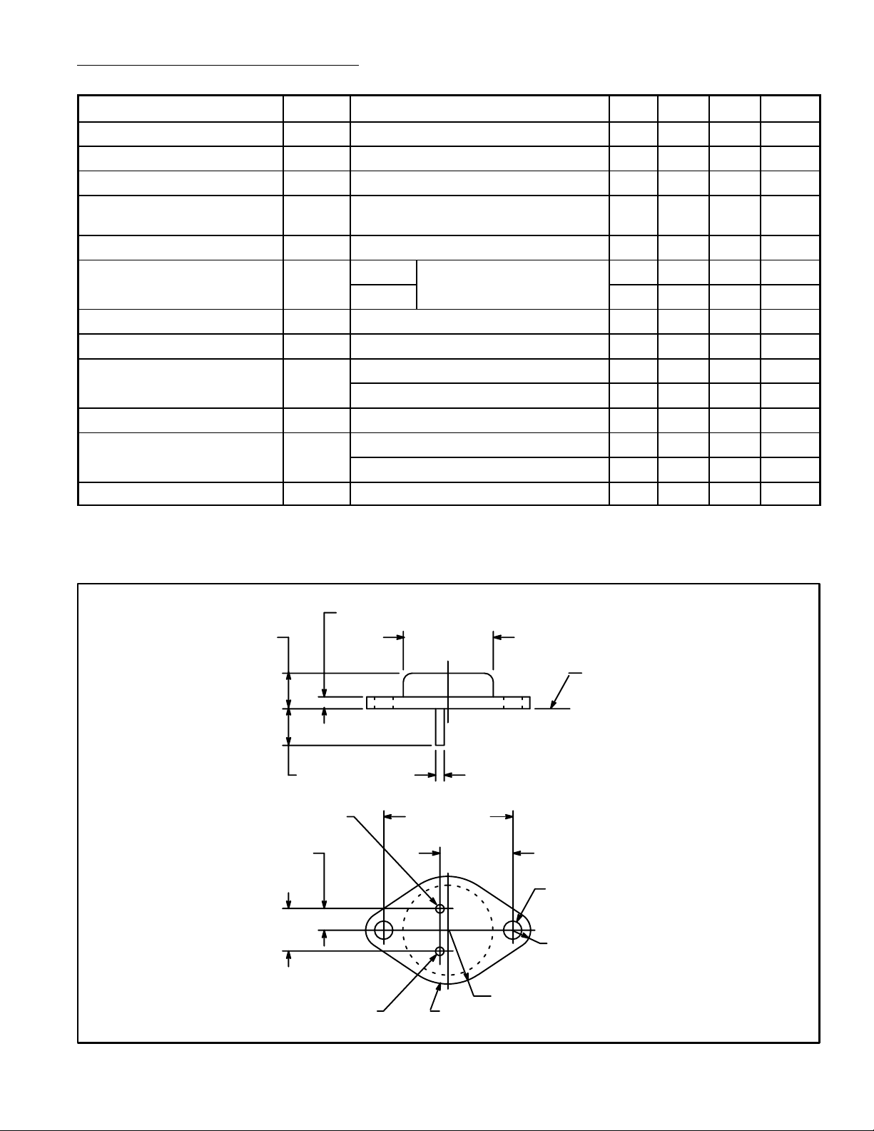
.350 (8.89)
.215 (5.45)
.430
(10.92)
.135 (3.45) Max
V
IN
Adjust
.875 (22.2)
Dia Max
1.187 (30.16)
.665
(16.9)
V
OUT
Seating
Plane
.040 (1.02).312 (7.93) Min
.156 (3.96) Dia
(2 Holes)
.188 (4.8) R Max
.525 (13.35) R Max
/Case
 Loading...