

Page 1

NTE6070 thru NTE6079
85 Amp Stud Mount Rectifiers
Description:
The NTE6070 thru NTE6079 series of 85 Amp power rectifiers are stud mounted DO–5 packages.
Because the silicon junction is carefully fitted within a glass to–metal hermetically sealed case, reliable operation is assured, even with extreme humidity and under other severe environmental conditions.
A double diffused, passivated junction technique is utilized to provide stable uniform electrical characteristics. Inherent in their design are very low leakage currents and excellent surge handling capability. These devices are available in standard and reverse polarities and in voltage ratings from 200 to
1600 volts PRV.
NTE silicon power rectifiers are ideal for a broad range of commercial and military uses including power supplies, ultrasonic systems, inverters, welders, emergency generators, battery chargers, DC motors, and motor controls.
Electrical Ratings:
Peak Reverse Voltage, P
NTE6074, NTE6075* 200V. . . . . . . . . . . . . . . . . . . . . . . . . . . . . . . . . . . . . . . . . . . . . . . . . . . . . . . .
NTE6076, NTE6077* 600V. . . . . . . . . . . . . . . . . . . . . . . . . . . . . . . . . . . . . . . . . . . . . . . . . . . . . . . .
NTE6078, NTE6079* 1200V. . . . . . . . . . . . . . . . . . . . . . . . . . . . . . . . . . . . . . . . . . . . . . . . . . . . . . .
NTE6070, NTE6071* 1600V. . . . . . . . . . . . . . . . . . . . . . . . . . . . . . . . . . . . . . . . . . . . . . . . . . . . . . .
Maximum Forward Current (T
Maximum Surge Current, Single Cycle, I
Maximum Forward Voltage Drop (I
Maximum Reverse Current (FCA @ 150°C), I
Maximum I
2
t (Less than 8ms), I2t 9300A2Sec. . . . . . . . . . . . . . . . . . . . . . . . . . . . . . . . . . . . . . . . . . . . . .
Reverse Power for Bulk Avalanche 0.6 Joules. . . . . . . . . . . . . . . . . . . . . . . . . . . . . . . . . . . . . . . . . . . . .
Storage Temperature Range, T
Operating Temperature Range, T
Maximum Thermal Resistance, Junction–to–Case, R
RV
= +132°C, Single Phase Half Wave), I
C
FM(Surge)
= 200A), V
F
stg
opr
F
R
thJC
F
85A. . . . . . . . . . . . . . . . . . . .
1500A. . . . . . . . . . . . . . . . . . . . . . . . . . . . . . . . . . . . .
1.15V. . . . . . . . . . . . . . . . . . . . . . . . . . . . . . . . . . . . .
2mA. . . . . . . . . . . . . . . . . . . . . . . . . . . . . . . . . . . . . . . .
–65° to +200°C. . . . . . . . . . . . . . . . . . . . . . . . . . . . . . . . . . . . . . . . . .
–65° to +190°C. . . . . . . . . . . . . . . . . . . . . . . . . . . . . . . . . . . . . . . .
0.6°C/W. . . . . . . . . . . . . . . . . . . . . . . . . . . .
Note 1. * Indicates Anode to case polarity, Cathode to case is standard polarity.
Page 2
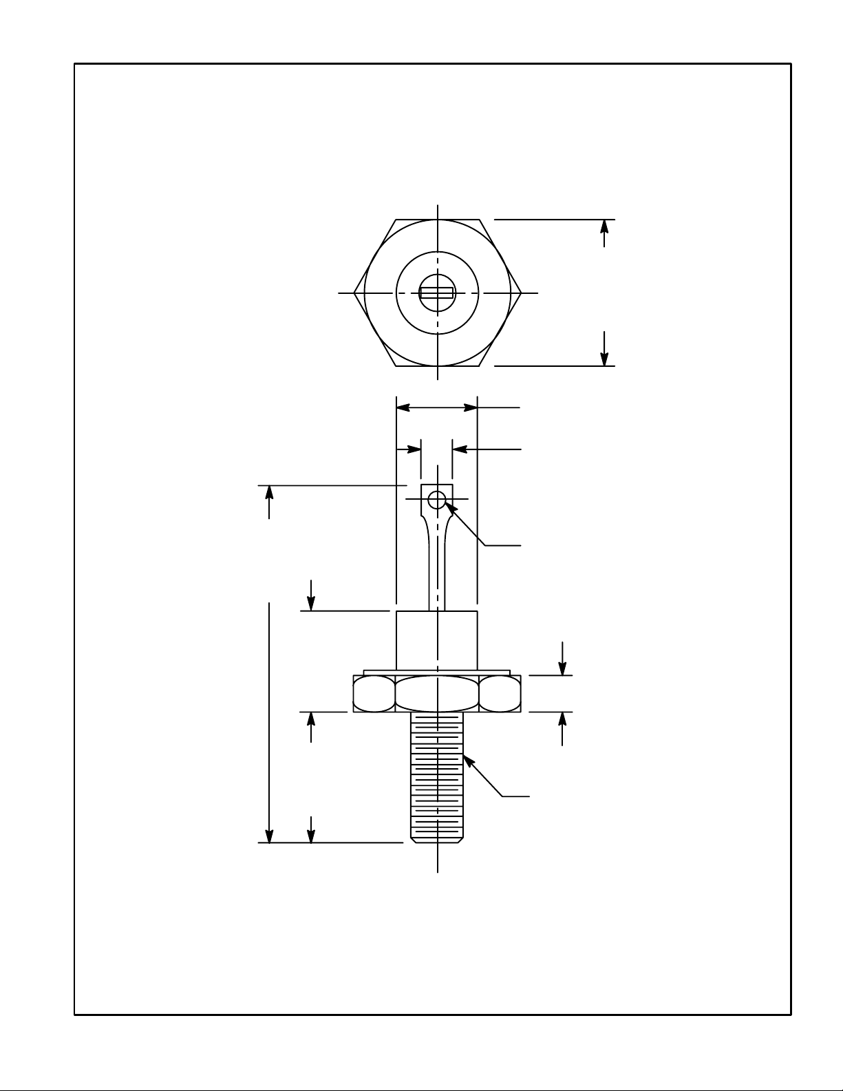
.687
(17.4)
Max
.667 (16.9) Dia Max
.375 (9.55) Max
1.288
(32.71)
Max
.450
(11.4)
Max
.453
(11.5)
Max
.140 (3.65) Dia Max
.200 (5.08) Max
1/4–28 UNF–2A
 Loading...