

Page 1

NTE3095
Optoisolator
Description:
The NTE3095 is a dual photocoupler optoisolator in an 8–Lead DIP type package consisting of a pair
of Gallium Aluminum Arsenide light emitting diodes and integrated photodetectors. Separate connections for the photodiode bias and output transistor collectors improve the speed up to a hundred
times that of a conventional phototransistor coupler by reducing the base–collector capacitance.
Features:
D TTL Compatible
D High Switching Speed
Absolute Maximum Ratings:
LED
Forward Current (Each Channel), I
F
Derate above +70°C 0.8mA/°C. . . . . . . . . . . . . . . . . . . . . . . . . . . . . . . . . . . . . . . . . . . . . . . . . . . . .
Pulse Forward Current (Each Channel, Note 1), I
FP
Derate above +70°C 1.6mA/°C. . . . . . . . . . . . . . . . . . . . . . . . . . . . . . . . . . . . . . . . . . . . . . . . . . . . .
Total Pulse Forward Current (Each Channel, Note 2), I
Reverse Voltage (Each Channel), V
Diode Power Dissipation (Each Channel), P
R
D
Derate above +70°C 0.9mW/°C. . . . . . . . . . . . . . . . . . . . . . . . . . . . . . . . . . . . . . . . . . . . . . . . . . . .
FPT
25mA. . . . . . . . . . . . . . . . . . . . . . . . . . . . . . . . . . . . . . . . . . . . . . . .
50mA. . . . . . . . . . . . . . . . . . . . . . . . . . . . . . . . . . .
1A. . . . . . . . . . . . . . . . . . . . . . . . . . . . . . . .
5V. . . . . . . . . . . . . . . . . . . . . . . . . . . . . . . . . . . . . . . . . . . . . . . . . .
45mW. . . . . . . . . . . . . . . . . . . . . . . . . . . . . . . . . . . . . . . .
DETECTOR
Output Current (Each Channel), I
Peak Output Current (Each Channel), I
Supply Voltage, V
CC
Output Voltage (Each Channel), V
O
OP
O
Output Power Dissipation (Each Channel), P
–0.5 to +15V. . . . . . . . . . . . . . . . . . . . . . . . . . . . . . . . . . . . . . . . . . . . . . . . . . . . . . . .
–0.5 to +15V. . . . . . . . . . . . . . . . . . . . . . . . . . . . . . . . . . . . . . . . . . .
O
8mA. . . . . . . . . . . . . . . . . . . . . . . . . . . . . . . . . . . . . . . . . . . . . . . . . .
16mA. . . . . . . . . . . . . . . . . . . . . . . . . . . . . . . . . . . . . . . . . . .
35mW. . . . . . . . . . . . . . . . . . . . . . . . . . . . . . . . . . . . . . .
Derate above +70°C 1mW/°C. . . . . . . . . . . . . . . . . . . . . . . . . . . . . . . . . . . . . . . . . . . . . . . . . . . . . .
COUPLED
Operating Temperature Range, T
Storage Temperature Range, T
opr
stg
Lead Temperature (During Soldering, 1.6mm below seating plane, 10s), T
Isolation Voltage (AC, 1min., R.H. ≤ 60%, Note 3), V
. . . . . . . . . . . . . . . . . . . . . . . . . . . .
ISO
L
–55° to +100°C. . . . . . . . . . . . . . . . . . . . . . . . . . . . . . . . . . . . . . . .
–55° to +125°C. . . . . . . . . . . . . . . . . . . . . . . . . . . . . . . . . . . . . . . . . .
+260°C. . . . . . . . . . . . .
2500V
rms
Note 1. Pulse Width = 1ms, Duty Cycle = 50%
Note 2. Pulse Width = 1µs, 300pps.
Note 3. Device considered a two terminal device. Pins 1, 2, 3, and 4 shorted together and Pins 5,
6, 7, and 8 shorted together.
Page 2
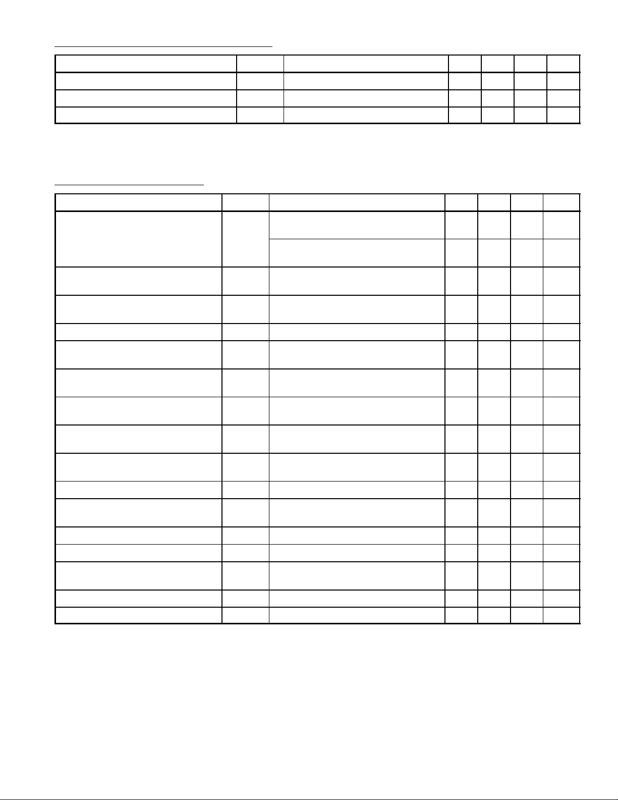
Recommended Operation Conditions:
Parameter Symbol Test Conditions Min Typ Max Unit
Supply Voltage V
Forward Current, Each Channel I
Operating Temperature T
CC
F
opr
0 – 12 V
– 16 25 mA
–25 – +85 °C
Electrical Characteristics: (TA = 0° to +70°C, Note 4 unless otherwise specified)
Parameter Symbol Test Conditions Min Typ Max Unit
Current Transfer Ratio
(Each Channel)
Logic Low Output Voltage
(Each Channel)
Logic High Output Current
(Each Channel)
Logic Low Supply Current I
CTR
V
OL
I
OH
CCL
IF = 16mA, VO = 0.4V, VCC = 4.5V,
TA = +25°C, Note 5
IF = 16mA, VO = 0.5V, VCC = 4.5V,
Note 5
IF = 16mA, IO = 2.4mA, VCC = 4.5V – 0.1 0.4 V
IF = 0mA, VO = VCC = 5.5V,
TA = +25°C
IF = 0mA, VO = VCC = 15V – – 50 µA
IF1 = IF2 = 16mA, VO1 = VO2 = Open,
VCC = 15V
19 30 – %
15 – – %
– 3 500 nA
– 160 – µA
Logic High Supply Current I
CCH
IF1 = IF2 = 0mA, VO1 = VO2 = Open,
– 0.05 4.0 µA
VCC = 15V
Input Forward Voltage
V
IF = 16mA, TA = +25°C – 1.66 1.7 V
F
(Each Channel)
Temperature Coefficient of Forward
Voltage (Each Channel)
Input Reverse Breakdown Voltage
∆VF/∆TAIF = 16mA – –2 – mV/°
C
BV
IR = 10µA, TA = +25°C 5 – – V
R
(Each Channel)
Input Capacitance (Each Channel) C
Input–Output Insulation Leakage
Current
Resistance (Input–Output) R
Capacitance (Input–Output) C
Input–Input Leakage Current I
Resistance (Input–Input) R
Capacitance (Input–Input) C
I
I–O
I–O
I–O
I–I
f = 1MHz, VF = 0 – 60 – pF
IN
Relative Humidity = 45%, t = 5s,
V
= 3000V, TA = +25°C, Note 3
I–O
V
= 500V, Note 3 – 10
I–O
– – 1.0 µA
12
f = 1MHz, Note 3 – 0.6 – pF
Relative Humidity = 45%, t = 5s,
V
= 500V, Note 6
I–I
V
I–I
I–I
= 500V, Note 6 – 10
I–I
f = 1MHz, Note 6 – 0.25 – pF
– 0.005 – µA
11
– W
– W
Note 3. Device considered a two terminal device. Pins 1, 2, 3, and 4 shorted together and Pins 5,
6, 7, and 8 shorted together.
Note 4. All typicals at TA = +25°C.
Note 5. DC Current T ransfer Ratio is defined as the ratio of output collector current, IO, to the forward
LED input current, IF, times 100%.
Note 6. Measured between Pins 1 and 2 shorted together, and Pins 3 and 4 shorted together.
Page 3

Switching Characteristics: (TA = +25°C, VCC = 5V, IF = 16mA unless otherwise specified)
Parameter Symbol Test Conditions Min Typ Max Unit
Propagation Delay Time to Logic
Low at Output (Each Channel)
Propagation Delay Time to Logic
High at Output (Each Channel)
Common Mode Transient Immunity
at Logic High Level Output
(Each Channel)
Common Mode Transient Immunity
at Logic Low Level Output
(Each Channel)
Bandwidth (Each Channel) BW RL = 100Ω, Note 8 – 2 – MHz
t
pHL
t
pLH
CM
CM
RL = 1.9kΩ – 0.2 0.8 µs
RL = 1.9kΩ – 0.3 0.8 µs
HIF
L
= 0mA, VCM = 400V
RL = 1.9kΩ, Note 7
IF = 16mA, VCM = 400V
RL = 1.9kΩ, Note 7
P–P
P–P
,
,
– 1000 – V/µs
– –1000 – V/µs
Note 7. Common mode transient immunity in Logic High level is the maximum tolerable (positive)
dVcm/dt on the leading edge of the common mode pulse, Vcm, to assure that the output will
remain in a Logic High state (i.e., VO > 2V). Common mode transient immunity in Logic Low
level is the maximum tolerable (negative) dVcm/dt on the trailing edge of the common mode
pulse signal, Vcm, to assure that the output will remain in a Logic Low state (i.e., VO > 0.8V).
Note 8. The frequency at which the AC output voltage is 3dB below the low frequency asymptote.
Pin Connection Diagram
Anode 1
Cathode 1
1
2
3Cathode 2
4Anode 2
8
V
CC
7
VO1
6
VO2
GND
5
Page 4

.020 (.508)
Min
85
.250 (6.35)
14
.390 (9.9)
Max
.185
(4.7)
Max
Seating
Plane
.115 (2.94) Min.100 (2.54)
 Loading...