

Page 1
NTE1837
Integrated Circuit
TV Tuner Controller
Description:
The NTE1837 i s a t uner c ontroller integrated c ircuit i n a 1 6–Lead DIP type p ackage c ontaining f unctions
such as band s witch, i nverter, and low–pass f ilter. T his d evice c an b e u sed a s a f requency s ynthesizer
or a voltage synthesizer, depending on the external application circuit.
Functions:
D Band Switch (Equivalent to the NTE1658: Refer to the Truth Table)
D Inverter
D Low–Pass Filter (Voltage Follower, Operational Amplifier)
Features:
D 2–Input, 5–Output Band Switch
D Band Switch (NTE1658) Available by Changing Over C Pin
D High Maximum Output Current, Low Saturation Voltage
D Meet CATV Tuner Requirements
D Frequency Synthesizer or Voltage Synthesizer Application depending on Inverter and
Operational Amplifier Connections
Absolute Maximum Ratings:
(TA = +25°C unless otherwise specified)
Band Switch
V
Maximum Supply Voltage, V16max 18V. . . . . . . . . . . . . . . . . . . . . . . . . . . . . . . . . . . . . . . . . . . . . .
CC1
V
Maximum Supply Current, I1max 10mA. . . . . . . . . . . . . . . . . . . . . . . . . . . . . . . . . . . . . . . . . . . . . .
CC2
Maximum Load Current
I
, I13max (I1 = 6mA) –60mA. . . . . . . . . . . . . . . . . . . . . . . . . . . . . . . . . . . . . . . . . . . . . . . . . . . . . .
12
I
, I15max (V
14
= 12V) –60mA. . . . . . . . . . . . . . . . . . . . . . . . . . . . . . . . . . . . . . . . . . . . . . . . . . .
CC1
I11max 25mA. . . . . . . . . . . . . . . . . . . . . . . . . . . . . . . . . . . . . . . . . . . . . . . . . . . . . . . . . . . . . . . . . . . .
Maximum AB Input Current, I
Maximum Applied Voltage (SW), V
, I3max 2mA. . . . . . . . . . . . . . . . . . . . . . . . . . . . . . . . . . . . . . . . . . . . . . . .
2
max 35V. . . . . . . . . . . . . . . . . . . . . . . . . . . . . . . . . . . . . . . . . . . . . .
11
Inverter, Operation Amplifier
V
Maximum Supply Voltage, V6max 35V. . . . . . . . . . . . . . . . . . . . . . . . . . . . . . . . . . . . . . . . . . . . . . .
CC3
V
Maximum Supply Current, I6max 5mA. . . . . . . . . . . . . . . . . . . . . . . . . . . . . . . . . . . . . . . . . . . . . . .
CC3
Maximum Applied Voltage, V
Maximum Load Current, I
Maximum Input Voltage, V
Maximum Input Current, I
max 35V. . . . . . . . . . . . . . . . . . . . . . . . . . . . . . . . . . . . . . . . . . . . . . . . . . . .
8
max 5mA. . . . . . . . . . . . . . . . . . . . . . . . . . . . . . . . . . . . . . . . . . . . . . . . . . . . . .
8
max 8V. . . . . . . . . . . . . . . . . . . . . . . . . . . . . . . . . . . . . . . . . . . . . . . . . . . . . . .
7
max 1mA. . . . . . . . . . . . . . . . . . . . . . . . . . . . . . . . . . . . . . . . . . . . . . . . . . . . . .
7
Maximum Input Voltage, V9max VCC –1V. . . . . . . . . . . . . . . . . . . . . . . . . . . . . . . . . . . . . . . . . . . . . . . . . .
Common to 1, 2
Allowable Power Dissipation (T
Operating Temperature Range, T
Storage Temperature Range, T
≤ +65°C), Pdmax 600mW. . . . . . . . . . . . . . . . . . . . . . . . . . . . . . . . . .
A
opr
stg
–20° to +65°C. . . . . . . . . . . . . . . . . . . . . . . . . . . . . . . . . . . . . . . . .
–55° to +125°C. . . . . . . . . . . . . . . . . . . . . . . . . . . . . . . . . . . . . . . . . .
Page 2
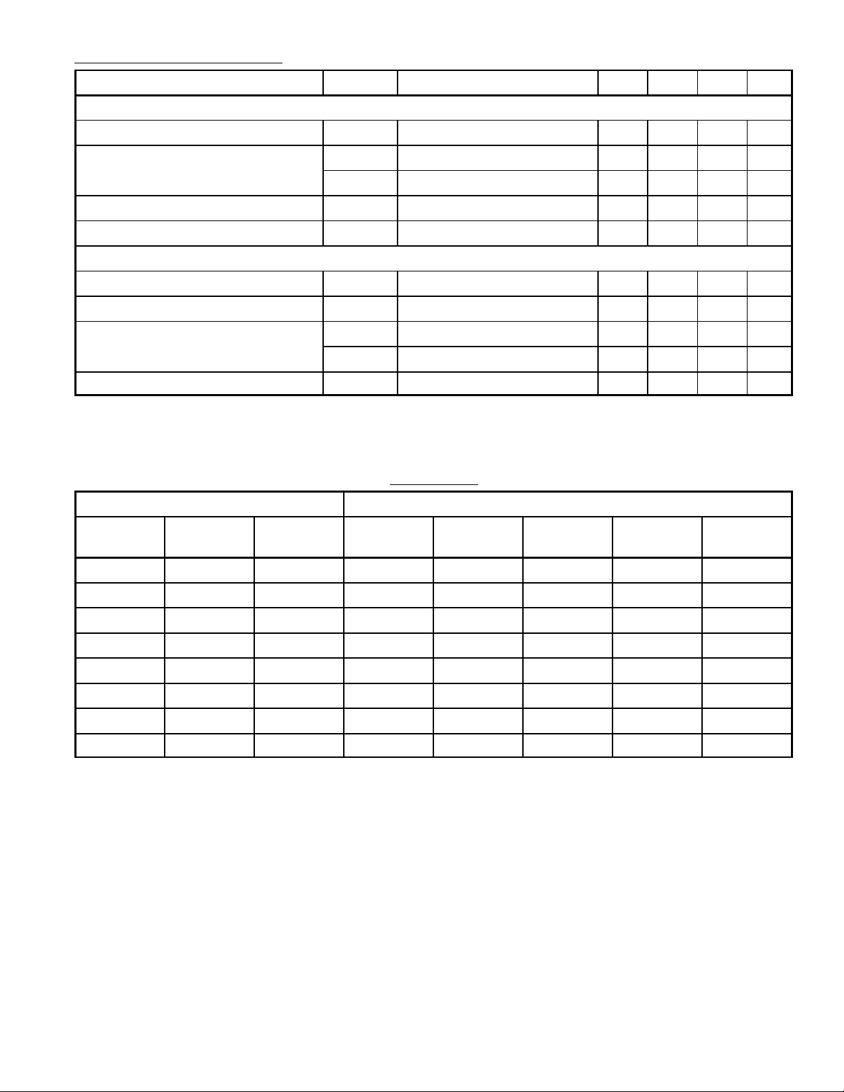
Operating Characteristics: (TA = +25°C unless otherwise specified)
Parameter Symbol Test Conditions Min Typ Max Unit
Band Switch
Quiescent Current I
CC
0 – 9 mA
Output Saturation Voltage F (sat) 0 – 0.7 V
SW (sat) 0 – 0.7 V
Input Threshold Voltage V
Output Leakage Current I
TH
L
0.8 1.5 3.0 V
0 – –50 µA
Inverter, Operational Amplifier, Zener
Output Saturation Voltage V
Input Threshold Voltage V
Input Offset Voltage V
V
Input Bias Current I
8 (sat)
TH
IO–1
IO–2
BIAS
0 – 0.3 V
2.5 – 4.5 V
–100 – +100 mV
–100 – +100 mV
– – –190 nA
Note 1. Current flowing into IC: Plus (No Sign)
Current flowing out of IC: Minus
Truth Table
Input Output
A
(Pin3)
B
(Pin2)
C
(Pin4)
F1
(Pin15)
F2
(Pin14)
F3
(Pin13)
F4
(Pin12)
SW
(Pin11)
L L Open H Z Z Z Z
H L Open Z H Z Z L
L H Open Z Z H Z L
H H Open Z Z Z H L
L L GND H Z Z H Z
H L GND Z H Z H L
L H GND Z Z H Z L
H H GND Z Z H H L
Note 2. Z: High Impedance
Page 3
Pin Connection Diagram
1
2
V
CC
Band Select Input A
Band Select Input B
Band Select Input C
2
3
4
5GND
3
6
V
CC
7Inverter Input
8Inverter Output 9 OP Amp Input
16 9
16
VCC 1
F1 Output to Tuner
15
F2 Output to Tuner
14
13
F3 Output to Tuner
12 F4 Output to Tuner
11 Switch Output to Tuner
10 OP Amp Output
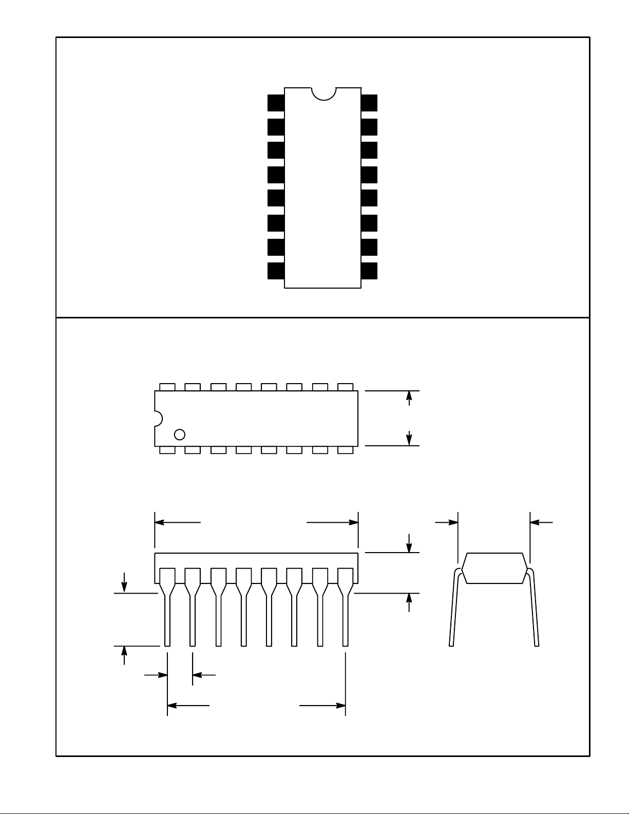
.245
(6.22)
Min
.260 (6.6) Max
18
.785 (19.9)
Max
.300
(7.62)
.200 (5.08)
Max
.100 (2.54)
.700 (17.7)
 Loading...