

Page 1
NTE1803
Integrated Circuit
Stereo Audio Control
Description:
The NTE1803 is an linear integrated circuit in a 18–Lead DIP type package designed as an active
stereo tone/volume control for car radios, TV receivers, and audio equipment. It includes functions
for bass and treble control, volume control with built–in contour (can be switched off), and balance.
All these functions can be controlled by DC voltages or by single linear potentiometers. The bass and
treble responses are defined by a single capacitor per control per channel.
Features:
D Few External Components Necessary
D Low Noise due to Internal Gain
D Bass Emphasis can be Increased by a Double–Pole Low–Pass Filter
D Wide Power Supply Range
Applications:
D Hi–Fi Radio
D Auto Radio
D TV
D Audio Systems
Absolute Maximum Ratings:
Supply Voltage (V
Total Power Dissipation, P
3–18
), V
CC
TOT
Operating Ambient Temperature Range, T
Storage Temperature Range, T
stg
20V. . . . . . . . . . . . . . . . . . . . . . . . . . . . . . . . . . . . . . . . . . . . . . . . . . . . . . . . .
1200mW. . . . . . . . . . . . . . . . . . . . . . . . . . . . . . . . . . . . . . . . . . . . . . . . . . .
A
–30° to +80°C. . . . . . . . . . . . . . . . . . . . . . . . . . . . . . . . . . .
–65° to +150°C. . . . . . . . . . . . . . . . . . . . . . . . . . . . . . . . . . . . . . . . . .
Page 2
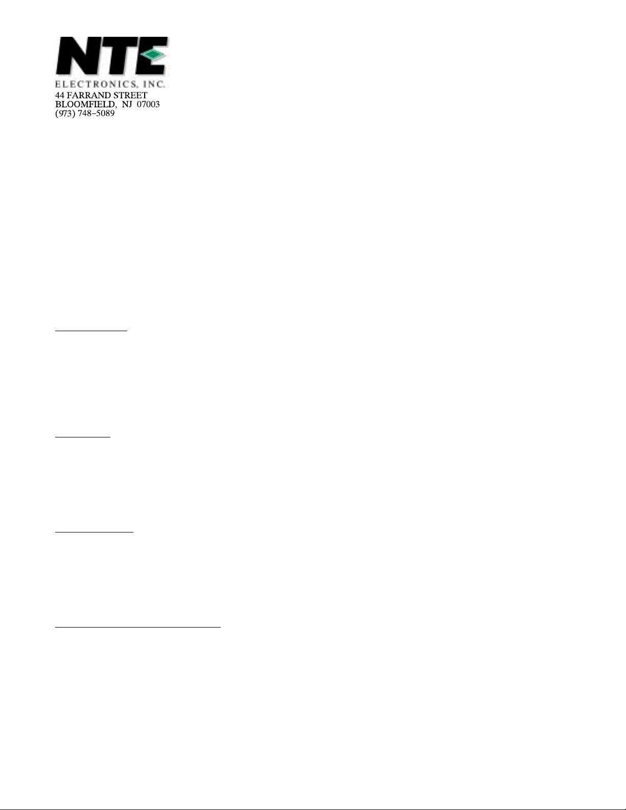
DC Electrical Charactertistics: (VCC = 12V, TA = +25°C, RG ≤ 600Ω, RL ≤ 4.7kΩ, CL ≤ 200pF
unless otherwise specified)
Parameter Symbol Test Conditions Min Typ Max Unit
Supply (Pin3)
Supply Voltage (VCC) V
Supply Current (IC) I
DC Input Levels (Pin4 and Pin15) V
DC Output Levels (Pin8 and Pin1 1) un-
4, 15–18VCC
V
8, 11–18
der all control voltage conditions
with DC feedback
with DC feedback
Pin17
Application with Internal Potentiometer V
Contour ON/OFF Switch ( Control by I17) –I
Application without Internal Potentiometer V
DC Control Voltage Range for volume, V
1, 9, 10, 16
bass, treble, and balance (Pin1,
Pin9, Pin10, and P in16 respectively)
3–18
3
17–18
17
17–18
7.5 – 16.5 V
VCC = 8.5V 19 27 36 mA
VCC = 12V 25 35 45 mA
VCC = 15V 30 43 56 mA
= 8.5V 3.8 4.25 4.7 V
VCC = 12V 5.3 5.9 6.6 V
VCC = 15V 6.5 7.3 8.2 V
VCC = 8.5V 3.3 4.25 5.2 V
VCC = 12V 4.6 6.0 7.4 V
VCC = 15V 5.7 7.5 9.3 V
VCC = 8.5V 3.5 3.75 4.0 V
Contour (Switch Open) – – 0.5 mA
Linear (Switch Open) 1.5 – 10 mA
VCC ≥ 10.8V, voltage range
4.5 – VCC/2–V
BE
V
forced to Pin17(Contour
cannot be switched OFF)
V
= 5V 1.0 – 4.25 V
17–18
Using internal supply 0.25 – 3.8 V
Input Current of Control Inputs (Pin1,
–I
1, 9, 10, 16
– – 5 µA
Pin9, Pin10, and Pin16)
AC Electrical Charactertistics: (VCC = V
tion), volume, balance, bass, and treble controls in mid–position, R
= 12V, TA = +25°C, contour switch closed (linear posi
3–18
≤ 600Ω, RL ≤ 4.7kΩ, CL ≤ 200pF,
G
f = 1kHz unless otherwise specified)
Parameter Symbol Test Conditions Min Typ Max Unit
Control Range
Maximum Gain of Volume AVmax 20.5 21.5 23 dB
Volume Control Range ∆A
Balance Control Range ∆A
Bass Control Range at 40Hz ∆A
Treble Control Range at 16kHz ∆A
Signal Inputs, Outputs
Input Resistance (Pin4 and Pin15) R
Output Resistance (Pin8 and Pin11) R
14,15
O8,11
AVmax/AVmin 90 100 – dB
V
AV = 0dB – –40 – dB
V
V
V
±12 ±15 – dB
±12 ±15 – dB
AV = 20dB, Note 1 10 – – kΩ
AV = –40dB, Note 1 – 160 – kΩ
– – 300 Ω
Note 1. Equation for input resistance:
R
=
I
160kΩ
1 + A
; AVmax = 12.
V
Page 3

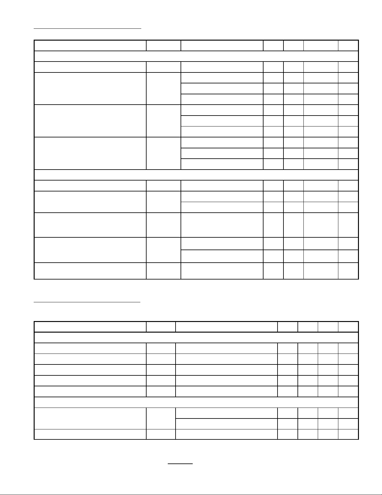
AC Electrical Charactertistics (Cont’d): (VCC = V
= 12V, TA = +25°C, contour switch closed
3–18
(linear position), volume, balance, bass, and treble controls in mid–position, R
≤ 200pF, f = 1kHz unless otherwise specified)
C
L
Parameter Symbol Test Conditions Min Typ Max Unit
Signal Processing
≤ 600Ω, RL ≤ 4.7kΩ,
G
Power Supply Ripple Rejection PSRR V
Channel Separation (250Hz to 10kHz) α
Spread of Volume Contol with Constant
∆A
CS
V
Control Voltage
Gain Tolerance Between Left and Right
∆A
V, L–RV16–18
Channel
Tracking Between Channels ∆A
V
Signal Handling with DC Feedback
Input Signal Handling V
Output Signal Handling (Note 2, Note 3) V
I(RMS)
O(RMS)
Noise Performance (VCC = 8.5V)
CC(RMS)
= 0dB
A
V
≤ 200mV, f = 100Hz,
35 50 – dB
AV = –20dB to +21.5dB 46 60 – dB
V
= 0.5V
1–18
= V
1–18
17–18
= 0.5V
AV = 21.5dB to –26dB,
17–18
– – ±3 dB
– – 1.5 dB
– – 2.5 dB
f = 250Hz to 6.3kHz,
balance adjusted at A
VCC = 8.5V, THD = 0.5%,
= 10dB
V
1.4 – – V
f = 1kHz (RMS Value)
VCC = 8.5V, THD = 0.7%,
1.8 2.4 – V
f = 1kHz (RMS Value)
VCC = 12V, THD = 0.5%,
1.4 – – V
f = 40Hz to 16kHz (RMS Value)
VCC = 12V, THD = 0.7%,
2.0 3.2 – V
f = 40Hz to 16kHz (RMS Value)
VCC = 15V, THD = 0.5%,
1.4 – – V
f = 40Hz to 16kHz (RMS Value)
VCC = 15V, THD = 0.7%,
2.0 3.2 – V
f = 40Hz to 16kHz (RMS Value)
VCC = 8.5V, THD = 0.5%,
1.8 2.0 – V
f = 1kHz (RMS Value)
VCC = 8.5V, THD = 10%,
– 2.2 – V
f = 1kHz (RMS Value)
VCC = 12V, THD = 0.5%,
2.5 3.0 – V
f = 40Hz to 16kHz (RMS Value)
VCC = 15V, THD = 0.5%,
– 3.5 – V
f = 40Hz to 16kHz (RMS Value)
Output Noise Voltage (Unweighted) at
f = 20Hz to 20kHz (RMS value)
Output Noise Voltage (Weighted) CCIR
recommendation 468–2 (peak value)
V
NO(RMS)
V
NO(M)
for maximum voltage gain, Note 4 – 260 – µV
AV = –3dB, Not e 4 – 70 140 µV
for maximum voltage gain, Note 4 – 890 – µV
for maximum emphasis of bass and
treble (contour OFF, A
= –40dB),
V
– 360 – µV
Note 4
Note 2. Frequencies below 200Hz and above 5kHz have reduced voltage swing. The reduction at
40Hz and at 16kHz is 30%.
Note 3. In the event of bass boosting the output signal handling is reduced. The reduction is 1dB
for maximum bass boost.
Note 4. Linear frequency response.
Page 4

AC Electrical Charactertistics (Cont’d): (VCC = V
= 12V, TA = +25°C, contour switch closed
3–18
(linear position), volume, balance, bass, and treble controls in mid–position, R
≤ 200pF, f = 1kHz unless otherwise specified)
C
L
Parameter Symbol Test Conditions Min Typ Max Unit
Noise Performance (VCC = 12V)
≤ 600Ω, RL ≤ 4.7kΩ,
G
Output Noise Voltage (Unweighted) at
f = 20Hz to 20kHz (RMS value),
Note 5
Output Noise Voltage (Weighted) CCIR
recommendation 468–2 (peak value)
Noise Performance (VCC = 15V)
Output Noise Voltage (Unweighted) at
f = 20Hz to 20kHz (RMS value),
Note 5
Output Noise Voltage (Weighted) CCIR
recommendation 468–2 (peak value)
V
NO(RMS)
V
NO(M)
V
NO(RMS)
V
NO(M)
for maximum voltage gain, Note 4 – 310 – µV
AV = –16dB, Note 4 – 100 200 µV
for maximum voltage gain, Note 4 – 940 – µV
for maximum emphasis of bass and
treble (contour OFF, A
for maximum voltage gain, Note 4 – 350 – µV
AV = –16dB, Note 4 – 110 220 µV
for maximum voltage gain, Note 4 – 980 – µV
for maximum emphasis of bass and
treble (contour OFF, A
Note 4. Linear frequency response.
Note 5. For peak values add 4.5dB to RMS values.
Pin Connection Diagram
= –40dB)
V
= –40dB)
V
– 400 – µV
– 420 – µV
Volume Control
Bypass
V
CC
Rt Ch Input
1
2
3
4
5Rt Ch Bass Capacitor
6Rt Ch Bass Capacitor
7Rt Ch Treble Capacitor
8Rt Ch Output 11 Lt Ch Output
9Bass Control 10 Treble Control
18
GND
17
Reference Control Voltage
16
Balance Control
15
Lt Ch Input
14 Lt Ch Bass Capacitor
13 Lt Ch Bass Capacitor
12 Lt Ch Treble Capacitor
Page 5

18 10
19
.870 (22.1) Max
.150
(3.8)
.100 (2.54) .125 (3.17) Min
.800 (20.3)
.250
(6.35)
 Loading...