

Page 1

NTE1731
Integrated Circuit
CMOS 10 Number Pulse Dialer
Description:
The NTE1731 is a CMOS LSI repertory dialer with ten 16–digit number memory storage in a 16–Lead
DIP type package. The pulse and mute signal outputs resulting from keyboard input are like those
of a pulse dialer. The NTE1731 incorporates a 64 x 10 bit RAM which is used to store the ten telephone numbers.
When used in a Public Branch Exchange (PBX) system, a Pause function is provided. This function
suspends dial pulse output upon pause detection (via # key input), and resumes the output after one
of the numeric keys is pressed.
Features:
D Make Ratio: 30/40% Pin Selectable
D Pulse Output: “0” True
D Mute Output: “0” True
D Stores Ten 16–digit Telephone Numbers
D One Temporary Memory and Permanent Memory Storage of Telephone Numbers are Possible
D Uses a CR Oscillator as a Frequency Reference
D Line Operation Off–Hook, Battery Operation On–Hook
D Uses Either a Standard 2–of–7 Matrix Keyboard or a Single Contact Keyboard
D PBX Pause Storage
Absolute Maximum Ratings:
Supply Voltage (Note 1), V
DD
Power Dissipation (Note 2), PD 500mW. . . . . . . . . . . . . . . . . . . . . . . . . . . . . . . . . . . . . . . . . . . . . . . . . . .
Maximum Pin Voltage 1 (Note 3), V
Maximum Pin Voltage 2 (Note 4), V
Operating Temperature Range, T
Storage Temperature Range, T
in1
in2
opr
–55° to +150°C. . . . . . . . . . . . . . . . . . . . . . . . . . . . . . . . . . . . . . . . . .
stg
–30° to +50°C. . . . . . . . . . . . . . . . . . . . . . . . . . . . . . . . . . . . . . . . .
Note 1. Referenced to GND
Note 2. TA = +25°C
Note 3. The Maximum applicable voltage on any pin with respect to GND
Note 4. The maximum applicable voltage on any pin with respect to V
DD
Recommended Operating Conditions:
Supply Voltage, V
DD
2.6V to 6.0V. . . . . . . . . . . . . . . . . . . . . . . . . . . . . . . . . . . . . . . . . . . . . . . . . . . . . . . .
6.2V. . . . . . . . . . . . . . . . . . . . . . . . . . . . . . . . . . . . . . . . . . . . . . . . . . . . . . .
–0.3V. . . . . . . . . . . . . . . . . . . . . . . . . . . . . . . . . . . . . . . . . . . . . . .
+0.3V. . . . . . . . . . . . . . . . . . . . . . . . . . . . . . . . . . . . . . . . . . . . . . .
Page 2
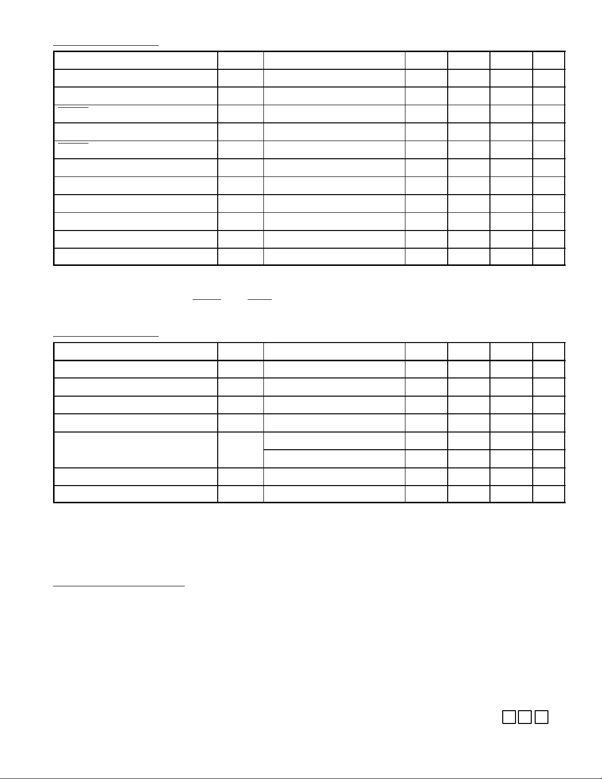
DC Characteristics: (–30°C x TA x =60°C unless otherwise specified)
Parameter Symbol Test Conditions Min Typ Max Unit
Standby Current I
Operating Current I
MUTE Sink Current I
Pulse Sink Current I
MUTE Pulse Leakage Current I
SB
OP
ML
PL
LKG
Key Contact Resistance RK
Keyboard Capacitance CK
“0” Logic Level V
“1” Logic Level V
Key Pull–Up Resistance K
Key Pull–Down Resistance K
VDD = 2.5V, Note 5 – 1.0 5.0 µA
VDD = 2.5V, Note 6 – 100 200 µA
VDD = 2.5V, VO = 0.5V 0.5 2.0 – mA
VDD = 2.5V, VO = 0.5V 1.0 4.0 – mA
VDD = 6V, VO = 6V – 0.001 1.0 µA
1
1
IL
IN
VDD = 4V, Note 7 – 100 – kΩ
RU
VDD = 4V, Note 7 – 5.0 – kΩ
RD
– – 1.0 kΩ
– – 3.0 pF
GND – 0.2V
0.8V
DD
– V
DD
DD
V
V
Note 5. All output pins in no–load condition when clock is stopped in Off–Hook mode.
Note 6. All output pins in no–load condition during key input, in either On–Hook or Off–Hook Mode.
Note 7. Resistance when ROW and COL pins are scanned at 125Hz and at high or low level.
AC Characteristics:
Parameter Symbol Test Conditions Min Typ Max Unit
Oscillator Frequency f
OSC
Key Debounce Time t
Oscillator Start–Up Time t
Pulse Rate P
Break Time t
DB
OS
Note 8 – 480 – kHz
Note 9, Note 10 – 32 – ms
– – 8.0 ms
Note 10 – 10 – pps
R
Pin9 = VDD, Note 10 – 60 – ms
B
Pin9 = GND, Note 10 – 68 – ms
Inter–Digital Pause Time t
Mute Overlap Time t
IDP
MOL
Note 10 – 840 – ms
Note 10 – 2 – ms
Note 8. Use elements with the following characteristics as the ceramic oscillator:
R < 20Ω, RA ≥ 70KΩ, CO ≤ 500pF.
Note 9. Key input is accepted if it is valid 32msec after the start of oscillation.
Note 10 . Changes in proportion to the frequency of the oscillator.
Functional Description:
Dialed Number Memory
During normal dialing, each digit is stored in the LND (Last Number Dialed) buffer, location 0. The
telephone number dialed can be left in this temporary LND buffer for later use or it can be copied into
any of the other nine permanent memory locations.
Telephone numbers to be automatically dialed by the NTE1731 may be entered into the LND buffer
while either On–Hook or Off–Hook.
Dialed Number Memory (Cont’d)
However, the NTE1731 must be in On–Hook mode for a number to be copied into a permanent
memory location. A number may be copied and stored by entering the key sequence
N∗∗
Page 3

(N = 1 to 9), followed by the address (1 to 9) of the memory location into which the number is to be
stored. This operation requires 300ms before going Off–Hook or reinitiating the store function. Information present in the LND buffer is replaced when new data is entered and cannot be recalled.
Automatic Dialing
The automatic dialing function is implemented by going Off–Hook and entering a
followed by the address (1 to 9) of the desired telephone number. Dialing will begin with the valid entry
of the address dey, and can be interrupted by initiating a new radial command. The LND buffer will
contain the information last entered. A key sequence of
to be redialed.
Normal dialing is performed when telephone numbers are input in the Off–Hook mode.
Pause Continue Command
The NTE1731 permits pauses to be programmed within the 1 to 15 digits of the telephone number.
This pause is input and stored in memory with the # key. If a pause code is detected during automatic
dialing, the dialing operation is suspended. Any key except the ∗ key is used to dial in data after the
pause, once the inter digital–pause time passes (CONTINUE command).
Normal dialing
Normal dialing is performed when telephone numbers are input in Off–Hook mode.
Sample Operation:
Example 1
0∗
will cause the last number entered
N∗
(N = 1 to 9),
1. On–Hook
2. Input “621–1221”“621–1221” is written into the memory buffer
3. Input “**5”“621–1221” is stored in location 5.
4. Off–Hook
5. Input “**5”“621–1221” is automatically dialed
Example 2
1. Off–Hook
2. Input PBX access code “42”“42” is written into memory and dialed.
3. While waiting for dial tone, enter “#”“#” is written into memory.
4. Dial “1–234–621–1221” The number is written into memory and dialed.
5. On–Hook
6. Input “**3”“42 #1–234–621–1221” is transmitted to location 3.
7. Off–Hook
8. Input “*3”“42” is dialed, then a pause occurs.
9. Enter ”3” (CONTINUE Command) “1–234–621–1221” is dialed.
while waiting for a dial tone.
Pin Description
VDD (Pin1)
Pin1 is the positive power supply pin with respect to the GND pin. Maximum input voltage is 6.0 Volts
Test Input (Pin2)
Pin2 is for testing the device. It should be connected to GND.
Keyboard Inputs (Pin3, Pin4, Pin5, Pin11, Pin12, Pin13, and Pin14)
The key entry is defined by either a single ROW being connected to a single COLUMN, or GND level
being simultaneously applied to both a ROW and a COLUMN. Consequently,either a single contact
or a standard 2–of–7 keyboard with GND common can be used.
Keyboard Inputs (Pin3, Pin4, Pin5, Pin11, Pin12, Pin13, and Pin14) (Cont’d)
The NTE1731 keyboard input pins are totally static until a valid key input is sensed. The oscillator
is then enabled and the rows and columns are alternately scanned (pulled high, then low) to verify
Page 4

that the input is valid. Keyboard bounce is ignored for 32ms after the initial key down is detected.
A key input is accepted if it is valid after this initial debounce time. This scheme allows any valid key
input to be recognized within 40ms of the initial key closure.
GND (Pin6)
Negative power supply pin.
Oscillator (Pins7 and Pin8)
The oscillator is formed by using a 480kHz ceramic resonator and two capacitors.
Make/Break Select (Pin9)
The Make/Break ratio may be selected by connecting this pin to either VDD or GND, Table 1 indicates
the two popular ratios from which the user can choose.
Table 1
Level of Pin9 Make Break
VDD (Pin1) 40% 60%
GND (Pin6) 32% 68%
Mute Output (Pin10)
Pin 10 is the output of an open–drain N–channel transistor, It provides the logic necessary to mute
the network while the telephone line is being pulled.
Hook Switch Input (Pin15)
The Hook Switch input pin requires an external pull–up resistor to the positive supply. A VDD input
puts the circuit into On–Hook mode, while a GND inputs puts it into OFF–Hook or dialing mode.
Pulse Output (Pin16)
The Pulse Output pin is a N–channel open drain output for driving an external transistor, this external
transistor is used to switch the loop current in a telephone line.
Pin Connection Diagram
V
DD
Test
Column Input
Column Input
1
2
3
4
5Column Input
6GND
16
Pulse Output
15
Hook Switch
14
Row Input
13
Row Input
12 Row Input
11 Row Input
7OSC Input
10 Mute Output
8OSC Output 9 Make/Break Select
Page 5

16 9
.260
(6.6)
Max
18
.245
(6.22)
Min
.785 (19.9) Max
.100 (2.54)
.700 (17.7)
.300 (7.62)
.200
5.08)
Max
 Loading...