

Page 1

NTE1720
Integrated Circuit
Pulse Width Modulator (PWM) Regulator
Description:
The NTE1720 PWM switching regulator control circuit contains all the essential circuitry to implement
single–ended or push–pull switching regulators. Included on the circuit are oscillator, voltage reference, a pulse width modulator, error amplifier, overload protection circuitry and output drivers.
A substance zener reference has been used to provide excellent stability with time and the reference
has been used to provide excellent stability with time and the reference is trimmed at the wafer level
to provide an initial accuracy of 2%. Additionally, the oscillator is trimmed to provide a medium tolerance of 6%.
Features:
D Reference Tolerance: ±2%
D Oscillator Tolerance: ±6%
D Long Term Stability: 10mV/1000 Hrs
D Operates Above 100kHz
Applications:
D Switching Power Supplies
D Motor Speed Control
D Off–Line Power Converters
Absolute Maximum Ratings:
Input Voltage, V
I
40V. . . . . . . . . . . . . . . . . . . . . . . . . . . . . . . . . . . . . . . . . . . . . . . . . . . . . . . . . . . . . . . . . . .
Reference Output Current 50mA. . . . . . . . . . . . . . . . . . . . . . . . . . . . . . . . . . . . . . . . . . . . . . . . . . . . . . . . .
Output Current (Each Output) 100mA. . . . . . . . . . . . . . . . . . . . . . . . . . . . . . . . . . . . . . . . . . . . . . . . . . . . .
Oscillator Charging Current (Pin6 or Pin7) 5mA. . . . . . . . . . . . . . . . . . . . . . . . . . . . . . . . . . . . . . . . . . . .
Internal Power Dissipation (Note 1), P
Operating Temperature Range, T
Storage Temperature Range, T
stg
D
opr
Lead Temperature (During soldering, 10 sec), T
–55°C to +125°C. . . . . . . . . . . . . . . . . . . . . . . . . . . . . . . . . . . . . .
–65°C to +150°C. . . . . . . . . . . . . . . . . . . . . . . . . . . . . . . . . . . . . . . .
L
1W. . . . . . . . . . . . . . . . . . . . . . . . . . . . . . . . . . . . . . . . . . . . . . .
+300°C. . . . . . . . . . . . . . . . . . . . . . . . . . . . . . . . . . . .
Note 1. For operating at elevated temperatures, the NTE1720 is derated at 150°C/W to a maximum
junction temperature of 115°C.
Page 2
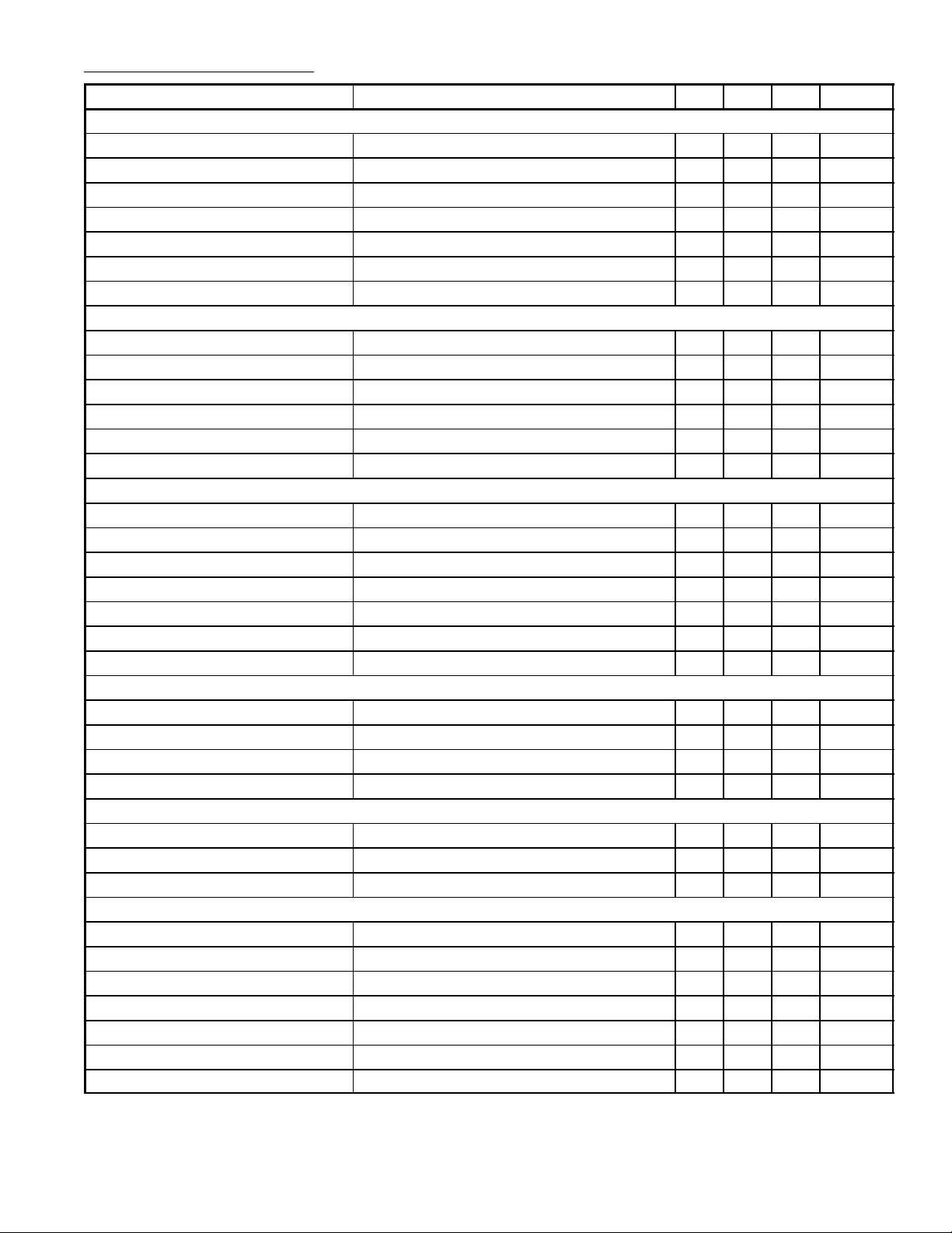
Electrical Characteristics: (TA = +25°C, VIN = 20V, f = 20kHz unless otherwise specified)
Parameter Test Conditions Min Typ Max Unit
Reference Section
Output Voltage 4.8 5.8 5.2 V
Line Regulation VIN = 8V to 40V – 10 20 mV
Load Regulation IL = 0mA to 20 – 20 50 mV
Ripple Rejection t = 120Hz – 66 – dB
Short Circuit Current Limit V
Temperature Stability – 0.3 1 %
Long Term Stability – 20 – mV/kHz
Oscillator Section
Maximum Frequency CT = 0.001pF, RT = 2kΩ – 300 – kHz
Initial Accuracy RT and CT Constant – 6 – %
Voltage Stability VIN = 8V to 40V – – 1 %
Temperature Stability – 2 – %
Output Amplitude Pin3 – 3.5 – µs
Output Pulse Width CT = 0.01µF, TA = 25°C – 0.5 – µs
Error Amplifier Section
Input Offset Voltage VCM = 2.5V – 0.5 5 mV
Input Bias Current VCM = 2.5V – 2 10 µA
Open Loop Voltage Gain 72 80 – dB
Common–Mode Voltage 1.8 – 3.4 V
Common–Mode Rejection Ratio – 70 – dB
Small Signal Bandwidth AV = 0dB – 3 – MHz
Output Voltage 0.5 – 3.8 V
Comparator Section
Minimum Duty Cycle – – 0 %
Maximum Duty Cycle 45 40 – %
Input Threshold Zero Duty Cycle – 1 – V
Input Bias Current – 1 – µA
Current Limiting Section
Sense Voltage Pin 9 = 2V with Error Amplifier Set for Max Out 180 200 220 mV
Sense Voltage T.C. – 0.2 – mV/°C
Common–Mode Voltage –1 – 1 V
Output Section (Each Output)
Collector–Emitter Voltage 40 – – V
Collector Leakage Current VCE = 40V – 0.1 50 µA
Saturation Voltage IC = 50mA – 1 2 V
Emitter Output Voltage VIN = 20V 17 16 – V
Rise Time RC = 2kΩ – 0.2 – µs
Fall Time RC = 2kΩ – 0.1 – µs
Total Standby Current VIN = 40V, Note 2 – 8 10 mA
= 0 – 100 – mA
REF
Note 2. Standby current does not include the oscillator charging current, error and current limit divid-
ers, and the outputs are open circuit.
Page 3

APPLICATIONS INFORMATION: (Functional Description and Pin Functions)
Voltage Regulator
The Internal 5V regulator (Input Pin15, output Pin16) supplies a regulated 5V to all Internal circuitry ,
as well as up to 50mA for external circuitry. For operation below 8V externally applied.
Oscillator
The Internal oscillator circuitry sets the frequency of operation for the switching regulator. The oscillator waveform is a ramp from about 1V to 3.5V (Pin7). Frequency is set by a timing resistor from Pin6
to ground and a capacitor from Pin7 to GND. The oscillator period is approximately RC for the recommended range of 1.8K to 100K for R and 0.001µF to 0.1µF for C.
The fall time of the ramp sets the blanking or dead time where both outputs are off in push–pull regulators. This is controlled by the value of the capacitor alone.
Output Transistors
The two output transistors have both the emitters (Pin11 and Pin14) and the collectors available
(Pin12 and Pin13). Internal current limiting for both of these transistors is about 100mA. The two
transistors are driven 180° out of phase by the flip–flop. For single–ended operation they should be
connected in parallel.
Error Amplifier
The differential Input (Pin1 and Pin2) single–ended output (Pin9) transconductance amplifier provides about 80dB of gain, as well as providing a point for loop frequency compensation or electronic
shutdown.
DC gain of the loop can be controlled by resistive loading, while AC compensation is usually accomplished with a series R–C conncected from Pin9 to GND. The output impedance at Pin9 is about 5MΩ
and current is about 200µA, so external op–amps or voltage sources can easily drive the comparator
input. Normally, the 5V reference is divided down to generate a voltage within the common mode
range of the error ampliifier.
Synchronous Operation
When an external clock is desired, a clock pulse of approximately 3V can be applied directly to the
oscillator output, Pin3. The impedance to GND at this point is approximately 2kΩ. In this configura-
tion, RT CT must be selected for a clock period slightly greater than that of the external clock.
If two or more NTE1720 regulators are to be operated synchronously, all oscillator output terminals
should be tied together. The oscillator programmed for the minimum clock period will be the master
from which all the other operate. In this application, the CT RT value of the slaved regulators must
be set for a period approximately 10% longer than that of the master regulator. In addition, CT (master)
= 2 CT (slave) to ensure that the master output pulse, which occurs first, has a wider pulse width and
will subsequently reset the slave regulators.
Shutdown
A logic high at Pin10 will shut down the regulator and cause both output transistors to turn off.
Current Limit
Current limiting is activated when the voltage between Pin4 and Pin5 exceeds 200mV. The output
of the current limit amplifier Internally sums with error amplifier to shorten the output pulse width. The
gain of the current limit circuitry is relatively low, so current control in limit is typically about 5%. Two
areas of caution should be observed with current limiting. First, the reponse time of the current limit
is set by the loop roll–off on Pin9. Fast current limiting requires external circuitry. Second, the common–mode range of the current limit amplifier is limited. Even fast spikes outside this range can disrupt operation.
Page 4

Pin Connection Diagram
R
C
1
2
3
4
5
6
T
7
T
Inverting Input
Non–Inverting Input
OSC Output
I
Sense (+)
LIMIT
I
Sense (–)
LIMIT
8GND 9 Compensation
16 9
16
V
ref
15
V
IN
Emitter B
14
13
Collector B
12 Collector A
11 Emitter A
10 Shutdown
18
.870 (22.0) Max .260 (6.6)
Max
.200
(5.08)
Max
.100 (2.54)
.099 (2.5) Min
.700 (17.78)
 Loading...