

Page 1
NTE1415
Integrated Circuit
Color Compensation Circuit
Absolute Maximum Ratings: (TA = +25°C unless otherwise specified)
Supply Voltage (V
Power Dissipation, P
Operating Temperature Range, T
Storage Temperature Range, T
Electrical Characteristics: (TA = +25°C unless otherwise specified)
Parameter Symbol Test Conditions Min Typ Max Unit
8–21
D
), V
CC
opr
stg
14.4V. . . . . . . . . . . . . . . . . . . . . . . . . . . . . . . . . . . . . . . . . . . . . . . . . . . . . . .
700mW. . . . . . . . . . . . . . . . . . . . . . . . . . . . . . . . . . . . . . . . . . . . . . . . . . . . . . . . . . .
–20° to +70°C. . . . . . . . . . . . . . . . . . . . . . . . . . . . . . . . . . . . . . . . .
–20° to +150°C. . . . . . . . . . . . . . . . . . . . . . . . . . . . . . . . . . . . . . . . . .
Circuit Current I
Tint Manual Output Level V
9–2(H)
V
Color Manual Output Level V
Tint Auto Output Level V
Color Auto Output Level V
20–21(H)
V
20–21(L)
11–21(H)VCC1
V
11–21(L)
19–21(H)VCC2
V
19–21(L)
VIR Detection Level V
Tint Manual Coltrol Sensitivity S
Color Manual Control Sensitivity S
Tint Auto Control Sensitivity S
Color Auto Control Sensitivity S
Tint Preference Control Sensitivity S
8
I
17
9–2(L)
VR
TM
CM
TA
CA
TP
= V
= V
20 26 33 mA
5 12 19 mA
10.3 11.0 11.7 V
0.6 1.3 2.0 V
9.5 10.2 10.9 V
0 – 0.3 V
= 12V 9.5 10.2 10.9 V
8–21
0.4 1.7 2.7 V
= 5.1V 10.1 10.9 11.7 V
17–21
0.4 1.8 3.1 V
0.23 0.28 0.33 V
0.83 0.94 1.05 times
0.86 0.97 1.08 times
40 43 46 dB
41.5 44.5 47.5 dB
–1.5 –1.3 –1.1 times
Page 2
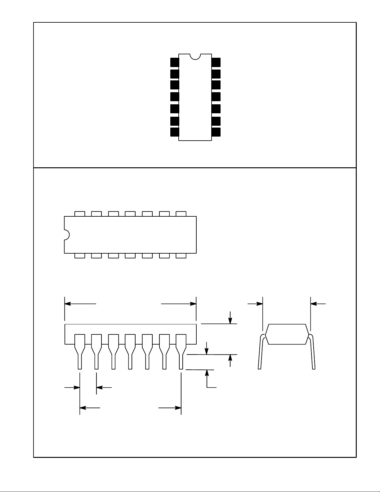
Pin Connection Diagram
To Chroma Processor
From Chroma Processor
Color Track Switch
GND
To Chroma Processor
To Chroma Processor
From Chroma Processor
1
2
3
4
5
6
7
14 8
Auto Color Switch Input
14
From Chroma Processor
13
12
V
CC
Auto Color Amp Output
11
Color Crystal
10
Color Crystal
9
22pF Bypass
8
17
.785 (19.95) Max
.300 (7.62)
.200
(5.08)
Max
.100 (2.45) .099 (2.5) Min
.600 (15.24)
 Loading...