

Page 1
Features
One touch redial operation
Tone/Pulse switchable
32 digit capacit y f or r edial i ng
Automati c mixed redialing (last number redial) of pulse
to DTMF with multi ple automatic access pauses
PABX auto-pause is 2.2 seconds
DTMF Timing:
Manual dialing: minimum duration for bursts and
pauses
Redialing: calibr at ed ti ming
Hands-Free control function
General Description
NT91214/15 Series
Tone/Pulse Dialer
Wi de operating vol t age range: 2V to 5.5V
Key-in beep tone output
Digits dialed manually after redialing are cascadable
and stored as additional digits for the next redialing
Uses inexpensive ceramic resonator (3.58 MHz)
Two versions for different telephone systems
Built-in power up reset circuit
Four extra function keys: flash, pause, redial and DP
or
DTMF mixed dialing
4 x 4 (or 2 x 8) keyboard can be used
Low standby current
The NT91214/15 is a single-chip, silicon gate, CMOS
integrated circuit with an on-chip oscillator for a 3.58MHz
crystal or ceramic r esonator. It pr ovides a dialing pul se
(DP) or dual tone multi-frequency (DTMF) dialing. A
standard 4 x 4 mat rix keyboard can be used to support
either DP or DTMF modes.
Up to 32 digits can be saved in the on-chip RAM for
redialing. In the DTMF mode, a short minimum tone
duration and minimum intertone pause allows rapid
dialing. Maximum tone duration depends on the key
depression time during manual dialing.
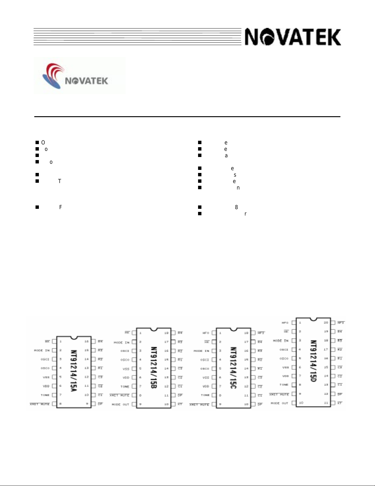
Pin Configurations
a. 16-Pin Package b. 18-Pin Packages c. 20-Pin Package
(i) Key Tone Output (ii) Hands-Fr ee Cont r ol
1V1.0
Page 2
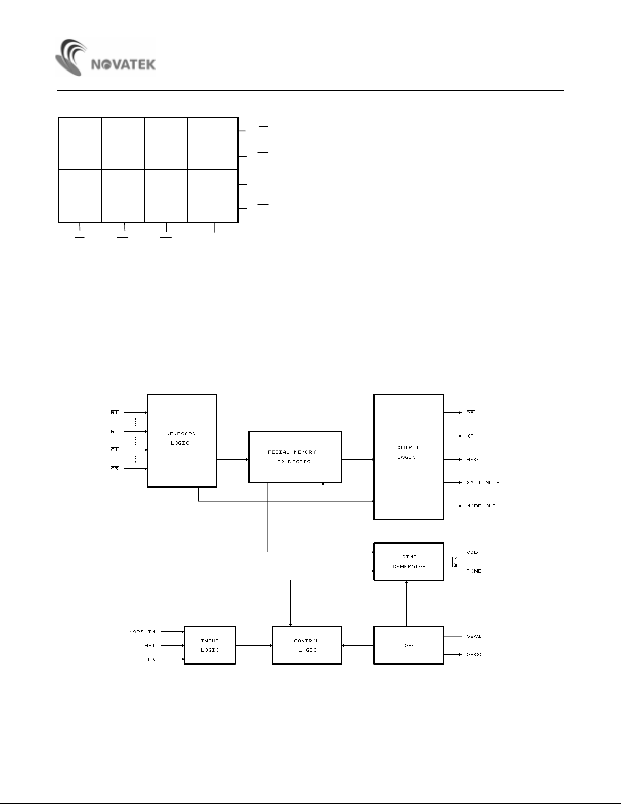
Keyboard Assignments
NT91214/15 Series
123F1
456F2
789 P
*/T 0 # RD
C1 C2 C3
1. */T -- In PULSE mode this key works as Pulse → DTMF key (T key). In DTMF mode the key works as * key.
*/T key will occupy one memory digit in either use.
2. F1 -- Flash key. The break time is 297 ms or 96 ms (NT91214/15 respectively)
3. F2 -- Flash key for break time 640 ms
4. P -- Pause key (2.2 seconds)
5. RD -- One key redial key
6. # -- In PULSE mode this key input is neglected. In DTMF mode this key works as # key.
GND
R1
R2
R3
R4
Block Diagram
V1.02
Page 3
NT91214/15 Series
Absolute Maximum Ratings*
Supply Voltage (VDD). . . . . . . . . . . . . . . . . . . .≤ 6.0V
IN
Input Voltage (V
Output Voltage (V
Output Vol tage (V
Tone Output Current (I
Power Dissipation (P
Operating Temperature (Top). . . . . . . -20°C to +70°C
Storage Temperature ( Tstg). . . . . . . - 40°C to +150°C
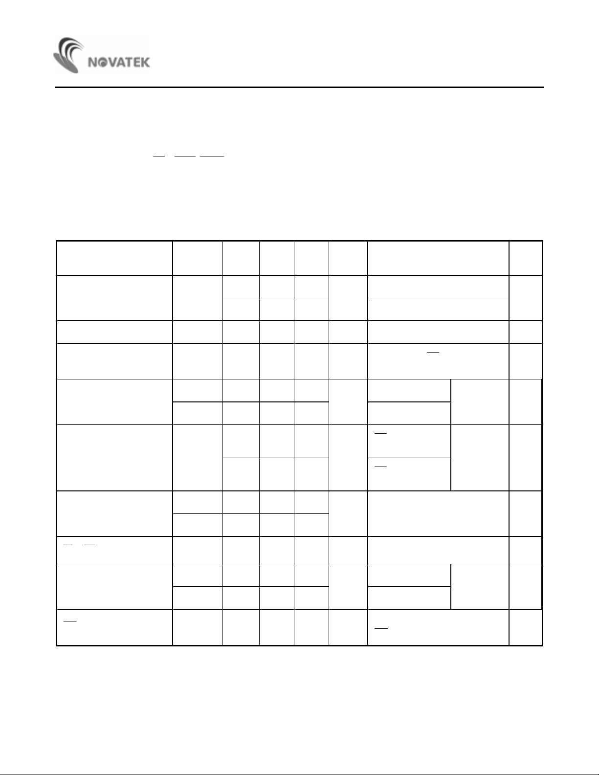
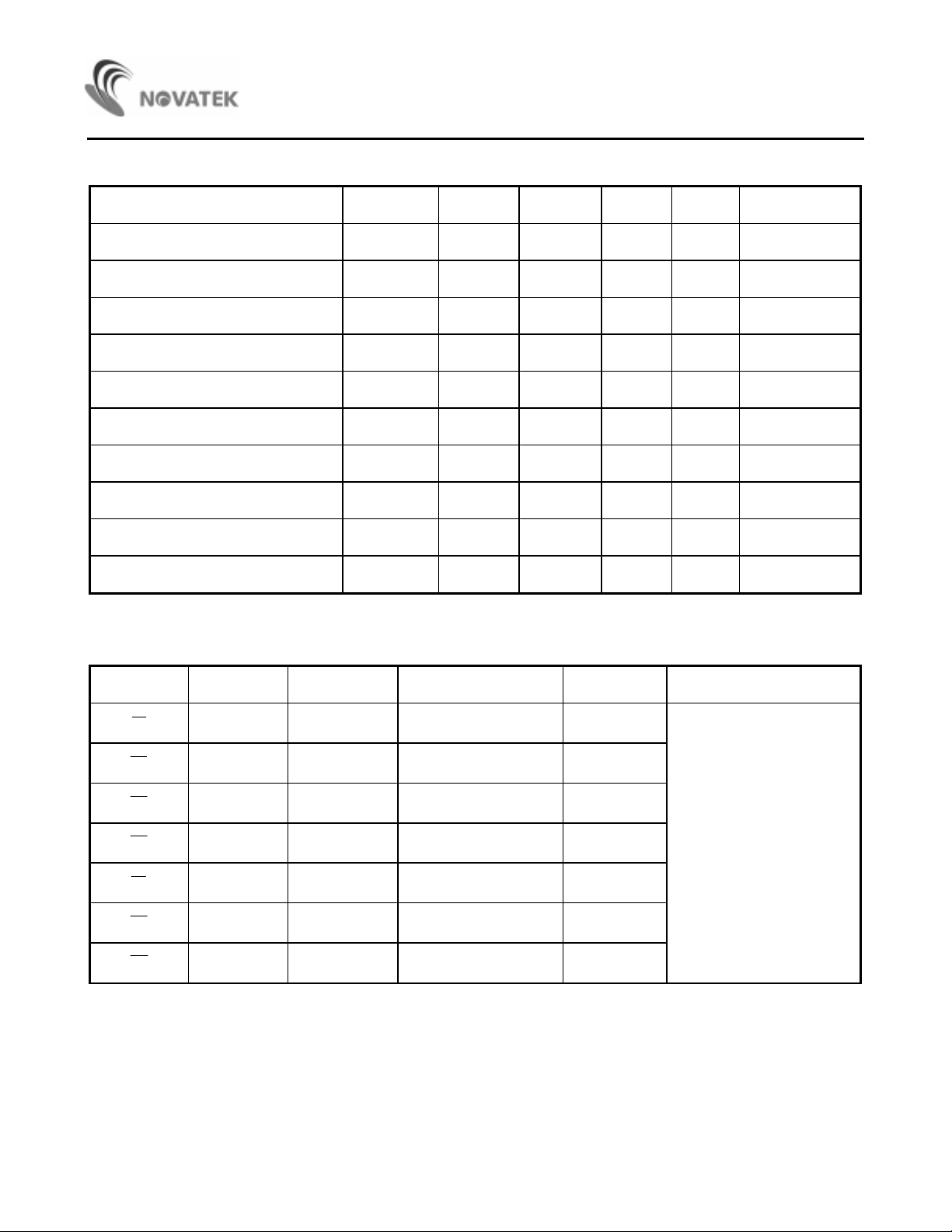
DC Electrical Characteristics
Parameter Symbol Min. Typ. Max. Unit Conditions
Operating Voltage VDD
Memory Retention Voltage V
Memory Retention Current I
) . . . . . . . VSS - 0. 3V t o VDD + 0. 3V
OUT
) . . . . VSS - 0.3 V to VDD + 0. 3 V
OUT
)(DP,
D
XMIT MUTE
TONE
) . . . . . . . . . . . . . . ≤50mA
) . . . . ≤1.2V
) . . . . . . . . . . . . . . . . . ≤500mW
(VDD = 3.5V, VSS = 0V, Fosc = 3. 579MHz, Top = 25°C)
2.0 5.5
2.0 5.5 TONE mode
MR
MR
1V -
0.05 0.4
*Comments
Stresses above those listed under "Absolute Maximum
Ratings" may cause permanent damage to this device.
These are stress ratings only. Functional operation of
this device at these or any other conditions above those
indicated in the operational sections of this specification
is not implied or intended. Exposure to the absolute
maximum rating conditions for extended periods may
affect device reliability.
Test
KT.
PULSE mode
V
HK
µ
VDD = 1.0V,
A
All outputs unl oaded
= VDD
A
-
DDP
Operating Current
I
I
DDT
Standby Current Iso
Input Current
V
V
R1
- R4 Input Current
Tone out Voltage
I
V
V
HFI
Pull Low Current
HFI
I
R
OC
OR
0.32 1.0
mA
0.6 2.0 Tone mode
0.03 0.05
µ
A
Pulse mode
HK
= VDD = 1.5V
All outputs A
unloaded
All outputs
unloaded,
A
no key
HK
0.5 10
IH
IL
0.8 1
VDD
00.2
115
584 730 876
µ
A
mVp-p
= VSS
Column
456 570 684 Row
VDD = 3.5V (Note 1)
5
µ
A
HFI
pin connected to 0V
selected
VDD = 3.5V D
L
R
= 5K
C
B
V1.03
Page 4
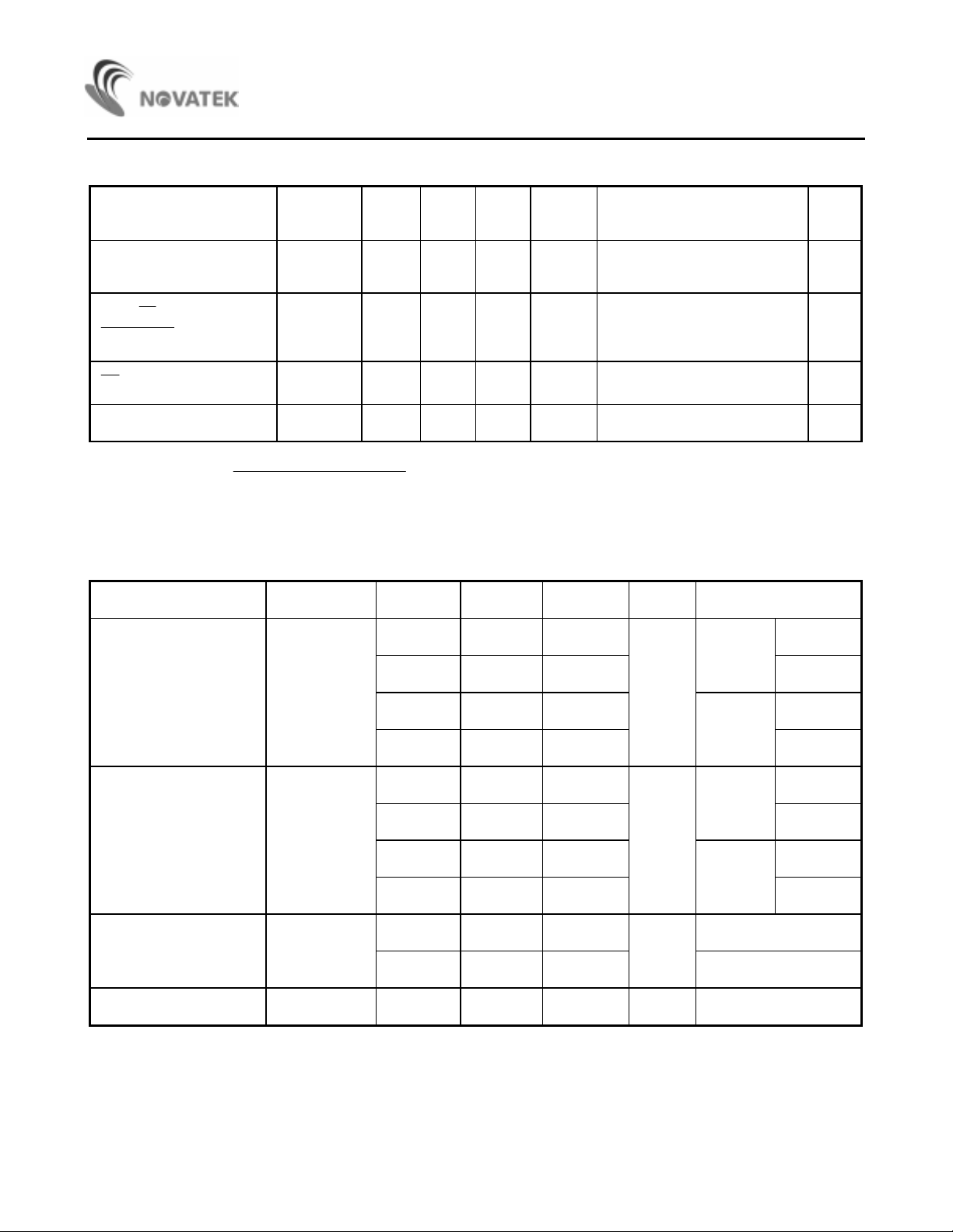
DC Electrical Characteristics (continued)
NT91214/15 Series
Parameter Symbol Min. Typ. Max. Unit Conditions
HFO Dri v e Cur r ent
HFO, KT, MODEOUT
XMITMUTE
DP
Sink Current
Sink Current
OH1
I
OL1
I
OL2
I
0.4 2 mA
0.9 5.3 mA
1.1 5.3 mA VDD = 3.5V , V
VDD = 3.5V
OH =
VDD - 0.4V
V
VDD = 3.5V
OL =
V
0.4V
Distortion DIS% 1 5 % * see note below
* Note: DIS% =
1
1. V
. . . . Vn are the intermodulati on or t he harmonic frequencies in the 500Hz to 3400Hz band.
IL
and VIH are the individual frequency components of the DTMFsignal.
2. V
AC Characteristics
22 2
12 n
100*(V V ... V )
+++
22
IL IH
+
(V V )
(VDD = 3.5V, VSS = 0V, F
1/2
1/2
OSC
= 3.579MHz, Top = 25°C, unless otherwise specified.)
Parameter Symbol Min. Typ. Max. Unit Conditions
33.3
OL =
0.4V B
10pps
Test
KT.
B
B
M/B = 1/2
Make Time T
Break Time T
Inter-digit Pause Time T
Pause Time T
M
B
IDP
PAU
40.0
16.7
ms
20pps
M/B = 2/3
M/B = 1/2
20.0 M/B = 2/3
66.6
60.0
33.3
10pps
ms
20pps
M/B = 1/2
M/B = 2/3
M/B = 1/2
30.0 M/B = 2/3
824
ms
10pps
458 20pps
2.2 sec
4V1.0
Page 5
AC Characteristics (co ntinued)
Parameter Symbol Min. Typ. Max. Unit Conditions
NT91214/15 Series
Auto-redial Break Tim e T
Delay time Key valid to Signal Out T
Key-in Debounce T
Key Release Debounce Tim e T
Key-in Tone Duration T
Key-in Tone Frequency F
Minimum Tone Duration Tim e T
Min. Tone Inter-digit Pause T
Redial Tone Duration T
Redial Tone Inter-digit Duration T
AOBK
D
KD
KLD
KTD
KT
MFD
TIDP
MFDR
TIDPR
2.2 sec * O ptional
0ms
21 ms
5.2 ms
23 ms
437 H
Z
94 ms
96 ms
94 ms
96 ms
Comparisons of Specified vs. Actual Tone Frequencies
R/C Spec. Actual Error (%) Unit Conditions
R1
R2
R3
R4
C1
C2
C3
697 699.1 +0.31 Hz
770 771.5 +0.19 Hz
852 852.3 +0.03 Hz
941 942.0 +0.10 Hz Fosc = 3.579MHz
1,209 1,215.7 +0.57 Hz
1,336 1,331.7 -0.32 Hz
1,477 1,471.9 -0.35 Hz
5V1.0
Page 6
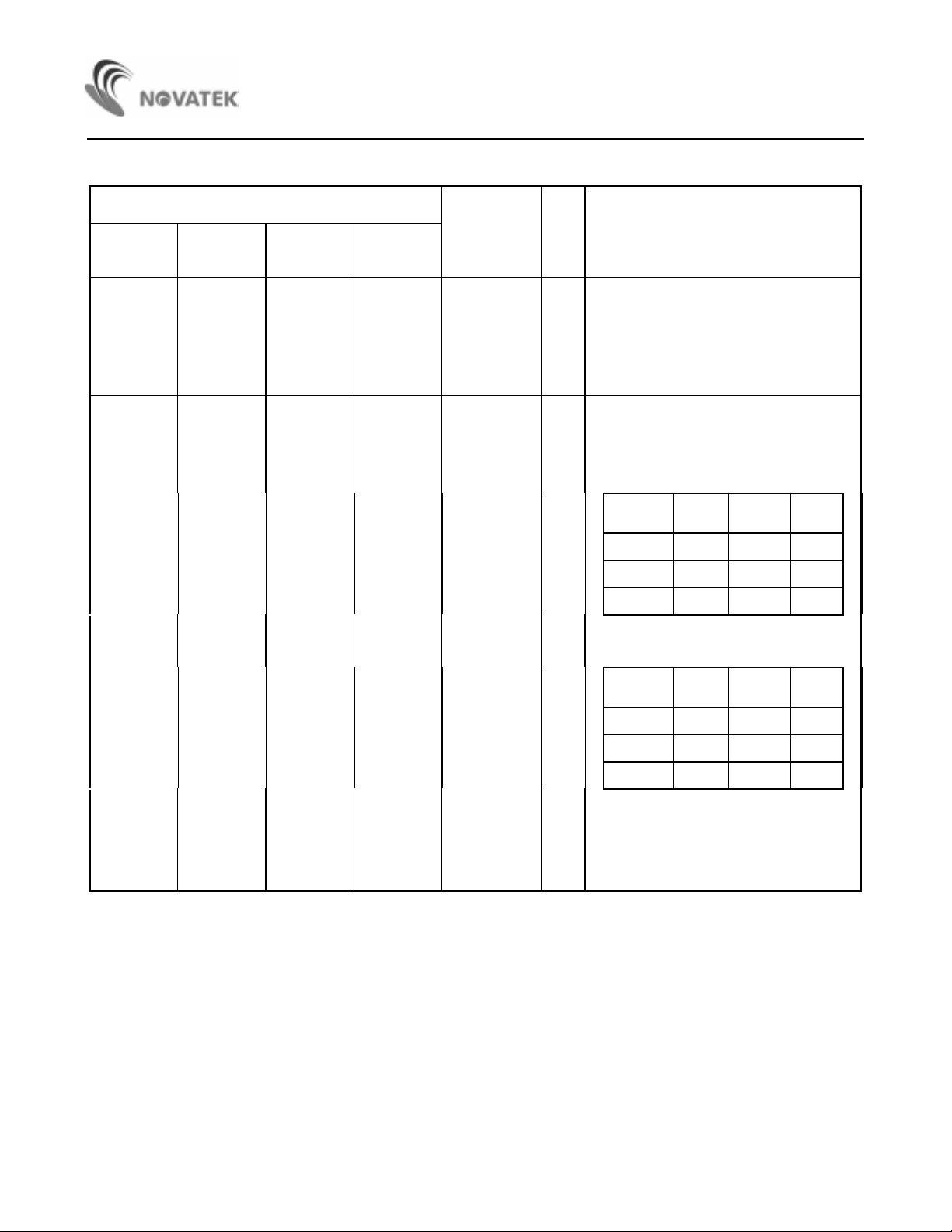
Pin Descrip t ions
NT91214/15 Series
Pin No.
NT91215A
NT91214A
3
4
2233MODE INI, ZTRI-STATE mode select pin
NT91215B
NT91214B
3
4
NT91215C
NT91214C
4
5
NT91215D
NT91214D
4
5
Designation I / O Description
OSCI
OSCO
I Oscillator Input and Output pins
The time base for the NT91214/15 is a
crystal controlled on-chip oscillator,
which is completed by connecting a
3.58MHz crystal or ceramic resonator
between the OSCI and OSCO pins.
There are two versions of the
NT91214/15 as follows:
a. NT91215 Series is for European and
American systems.
MODEINTone/
Pulse
VDD Pulse 10pps 2/3
VSS Tone - Floating Pulse 10pps 1/2
b. The NT91214 Series is for the
Japanese system.
MODEINTone/
Pulse
VDD Pulse 10pps 1/2
Dial
Rate
Dial
Rate
M/B
Ratio
M/B
Ratio
VSS Tone - Floating Pulse 20pps 1/2
The mode selection pin is checked for
tone/pulse dialing as each digit key
entery. In the PULSE mode, the dialing
rate is checked, along with the
make/break ratio, at first key entry.
6V1.0
Page 7
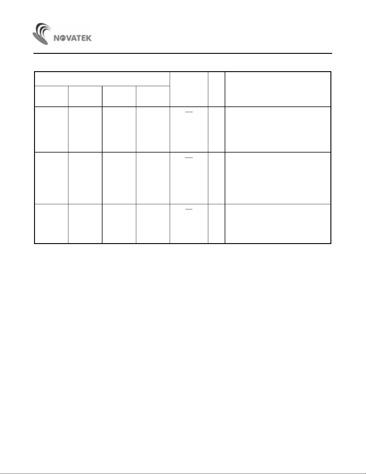
Pin Descrip t ions (cont inued)
Pin No.
NT91214/15 Series
NT91215A
NT91214A
1122
(N.A.) 10 (N.A.) 11
9 111012
NT91215B
NT91214B
NT91215C
NT91214C
NT91215D
NT91214D
Designation I/O Description
HK
KT
DP
I Hook switch i nput
This inverter input pin detects the state
of the hook switch contact . "Off Hook" is
represented by a VSS
Hook" is represented by a VDD
condition.
O Key-in tone output
This N-channel open drain pin sends out
a "beep" tone for each PULSE mode key
entry, along with entries of accepted
function keys (RD, T, F1 F2, and P
keys). The tone output frequency is
437Hz and tone duration is 23 ms.
O Dial ing pulse output
This is an N-channel open drain output.
The normal output will be "ON" during
break and "OFF" during make in the
PULSE DIALING mode.
condition. "On
7V1.0
Page 8

Pin Descrip t ions (cont inued)
Pin No.
NT91214/15 Series
NT91215A
NT91214A
(N.A.) (N.A.) Current
NT91215B
NT91214B
NT91215C
NT91214C
1 1 HFO O Hands-Free Control I/O pins
18 20
NT91215D
NT91214D
Designation I/O Description
These pins enable and disable the HandsFree control function. W hen input pin
goes low, the Hands-Free Control state is
toggled on. The status of the Hands-Free
control state is l isted in the following table:
Hook
sw.
- Low
HFI
IOn
Hook
Off
Hook
On
Hook
HFI
HFI
HFI
Off
Hook
Next State
High Yes
Low No
Low Yes
Low Yes
State
HFO Input HFO Dialing?
High
High
-
HFI
Off
Hook
Off
Hook
7788TONEOTone dialing output
When a valid keypress is detected in the
DTMF mode, appropriate low group and
high group, frequencies are generated
which hybridizes the dual tone output.
TONE output is in the "OFF" state in
PULSE mode.
Low
High
On
Hook
On
Hook
Low No
High Yes
8V1.0
Page 9

Pin Descrip t ions (cont inued)
Pin No.
NT91214/15 Series
NT91215A
NT91214A
8899
(N.A.) 9 (N.A.) 10 MODE OUT O Mode output pi n
13 15 14 16
14 16 15 17
15 17 16 18
16 18 17 19
10 12 11 13
NT91215B
NT91214B
NT91215C
NT91214C
NT91215D
NT91214D
Designation I/O Description
XMITMUTE
R1
R2
R3
R4
C1
O Dialing t r ansmission m ut e output
This is an N-channel open drain output
XMITMUTE
The
During pulse of DTMF dialing this
output is "ON".
This is an N-channel, open drain output
It is "ON" during t one output and "OFF"
during pulse output.
Keyboard pins
This input serves as the interface to an
XY matrix keyboard. On a 4 x 4 mat r ix
keyboard, the input from the fourth
column,
VSS.
C4
is normally "OFF"
, should be connected to
11 13 12 14
12 14 13 15
6677VDD
5566VSS
C2
C3
Power supply pins
These devices are designed to operate
from 2. 0V t o 5. 5V.
9V1.0
Page 10

Operatin g Procedures
Symbol Defini t ions:
In the description below, signals are defined in terms of
NT91214/15 Series
the key or switch which is activated.
OFF Hook means the phone is off the hook.
On Hook means that the phone is on the hook.
D1 represents f or the f irst digit di al ed in a string of
digits.
Dn ( Dk ) represents for the last digit dialed in a
string of di gi t s .
Dn+1 represents for the beginning of a new str i ng of
digits.
Dn+m represents for t he last digi t in a new st r i ng of
digits.
HFI
↓
represents for the switch that activates the
HANDS-FREE DIALING mode going low
*/T is the Pulse-to-DTMF key
HFI
↓
b. On Hook
Pulse mode is defined as the INITIAL mode, provided
the key input D1 is not */T while the mode
selection pin is VDD or floating. The chip will pause for
824 ms automatically after it detects an Off Hook
condition or if the
proceeds with pulse or DTMF dialing if any keys have
been depressed.
The dialing rate or make/break ratio is decided at the
first key entry by checking the MODE IN status and
will
not be altered. The MODE IN status can only switch
the DIALING mode from PULSE to DTMF after the
first
key entry.
D1 . . . Dn
HFI
↓
key is depressed. It then
RD is the Redial key.
0 is the Zero key.
P is the Pause key.
F is the Flash key.
Recommended O per at ion:
1. PULSE mode operation
a. Off Hook D1 . . . Dn
PULSE mode is defined as the INITIAL mode,
provided
the first keyboard input i s not the */T key f oll owing
the Off Hook condition and the mode selection pin
is
floating ( MODE IN = VDD or floating).
2. DTMF mode operation
a. Off Hook D1 . . . Dn or On Hook
D1 . . . Dn
DTMF mode is defined as the INITIAL mode if the
mode selection pin MODE IN is VSS.
b. Off Hook */T D1 . . . Dn or On Hook
HFI
↓
The INITIAL mode is PULSE mode if the mode
selection pin, MODE IN, is VDD or floati ng. The */T
key can switch the DIALING mode to TONE m ode.
Unlike NORMAL mode switching, the */T key
entry,
*/T D1 . . . Dn
HFI
↓
10 V1.0
Page 11

as the first key pressed, will not produce any pause
time. There are only 31 digits of redial memory
available in the buffer to be used for operations a
and b, since the mode switching key, */T , will
occupy one digit of space.
NT91214/15 Series
11 V1.0
Page 12

3. Manual dialing wit h aut omatic access pause
a. Off Hook O P D1 . . . Dn
pause key entries can be accepted and stored in the
redial memor y. Each is stored as a digit.
Each key-in will provide a pause of 3.57 seconds,
depending on which model is being used.
4. Redial
HFI
a. On Hook RD or On Hook
Up to 32 digits (in PULSE mode) or 31 digits
(in TONE mode) can be dialed using the RD key.
The RD key is disabl ed while PULSE or TONE
signals are being transmitted. Redial will also be
inhibited if the last num ber dialed exceeds 32 digits
↓
RD
NT91214/15 Series
The mode selection pin is alwsys checked for TONE
or PULSE mode key entry. Dialing can be switched
from PULSE to TONE mode, but not from TONE to
PULSE mode. Switching the MODE IN pin to the
original di gits plus the digits dialed after pressing
cause the chip to store a */T digit prior to the first
tone digit in the redial memory and will automatically
insert a 2.2 second pause before the tone digits are
dialed out. After the mode bas been switched, the
status of the mode selection pin will no longer be
checked. Therefore, it will not be possible to switch
from TONE to PULSE mode.
will
because the redial memory can only hold 32 digi t s .
b. Off Hook RD D1 . . . Dn or On Hook
HFI
↓
After pressing the RD key, digits may be added to
the number in redial memory. When finished
dialing,
the redial memory will contain the original digits,
plus the digit s dial ed after pressing RD . Each ti m e
the redial key is pressed, the stored number will be
dialed exactly the same as it was previously,
regardless of the status of the MODE IN pin.
5. TONE/PULSE switching operation
a. On Hook D1 . . . Dn MODE IN pin
PULSE Mode
DTMF Mode
RD D1 . . . Dn
switched to VSS Dn +1 . . . Dn+m
b. Off Hook D1 . . . Dn */T Dn+1
PULSE Mode
. . . Dn+m
DTMF Mode
PULSE mode is initially defined with the mode
selection pin, MODE IN, equal to VDD or floating. At
this time, the mode can be switched to DTMF by
pressing the */T key. DTMF mode will being as soon
as the last pulse has been transmitted. In this m ode,
Dn+1 through Dn+m are sent through the TONE
OUT pin as DTMF signals. If a P key entry is
Contained in the series of digits before or after the */T
entry, or the MODE IN switch is depressed, 2.2
second
pause will be added to the automatically inserted
pause time, which is also 3.57 seconds. Both of the
12 V1.0
Page 13

above switching modes can store as many as 31 digits
in the redial memory.
NT91214/15 Series
13 V1.0
Page 14

NT91214/15 Series
6. One-key redialing
Off Hook D1 . . . Dn RD or On Hook
D1 . . . Dn RD
If the dialing of D1 t o Dn is finished, pr essing
RD will cause the pulse dialing pin to go low for 1.67
seconds of break time and an 824 ms pause will
automatically be added. If the pulses of the number
dialed with D1 to Dn have not finished, the
pressing of the redial key will be ignored.
7. Flash diali ng
Off Hook F D1 . . . Dn or On Hook
HFI
↓
F D1 . . . Dn
The flash keys emulate quick On-Off Hook operations.
HFI
break of 96 ms or 640 ms (or, 297 ms or 640 ms,
↓
depending on the model) on the
DP
output pi n. Then, it
pauses for 824 ms and continues dialing the digits,
D1 to Dn . Th ese d igi ts are th en stored in the redial
memory.
Each time the flash key is pressed, the redial memory
will
be cleared to store a new entry. In addition, the MODE
IN
status will be checked again for the setting of the
TONE/PULSE DI ALING mode.
Simil arly, to make sure that the IC is work ing properly,
new flash key inputs will be ignored as long as the digit s
that were dialed have not finished.
Pressing the flash keys, F1 or F2 , will cause a
Timi ng Waveforms
1. Timing Waveform in PULSE Mode:
HK or HFO
Key Input
KT
XMIT MUTE
DP
Td: Delay time of Key valid to dialing signal out , typically 0m s
IDP
: Inter-digit pause time
T
KTO
: Key-in tone duration
T
KD
: Debouncing ti me
T
HK
Note: "
" or "HFO" indicates chip works when hook switch "HK" goes low or Hands-Free control output HFO goes
high.
2 3
TKD: debouncing time 21 ms
T
(23 ms), f = 437Hz
KTD
T
d
T
M
1
T
IDP
T
M
T
M
T
B
21ms
14 V1.0
Page 15

Timi ng Waveforms (cont inued)
2. Timing Waveform in TONE Mode:
(i) Normal Dialing
HK or HFO
NT91214/15 Series
Key Input
KT
XMIT MUTE
TONE
MODE OUT
(ii) After (i), Redialing
ÉÌ ðó ÉÇÐ
Ìæú Кпсцх
ÌÕ
ÙÎÊÕ ÎÖÕÆ
4 9
T
T
2.3ms
3
KD
d
ÓÅ
å
Õ
*
TMFD:94ms
2.5ms 2.3ms 2.3ms
T
:96ms
TIDP
ÎÇÅÓ
Õ
³¯¶îô
ÕÐÏÆ
ÎÐÅÆ ÐÖÕ
ХКЕСУ
Õ
15 V1.0
Page 16

Timi ng Waveforms (cont inued)
3. Timing waveform for SWITCHING Mode Operation:
(i) By mode selection pin swit ches
HK or HFO
NT91214/15 Series
Key Input
MODE IN
KT
DP
MODE OUT
XMIT MUTE
TONE
(ii) By */T key entry
ÉÌ ðó ÉÇÐ
Ìæú Кпсцх
ÎÐÅÆ ÊÏ
ÌÕ
ÅÑ
2 4
T
M
T
d
3
**** ***********************
T
IDPTIDP
³ µ
´
*/T
6
T
M
T
T
IDP
IDP
T
PAUTMFD
«°Õ
·
««««««««««««««««««««««««««««««««««««««««««««««««««««««««««««««««««
«
ÎÐÅÆ ÐÖÕ
ÙÎÊÕ ÎÖÕÆ
ÕÐÏÆ
PAU
T
: Pause time (2.2 secs)
Î
Õ
å
Õ
ÊÅÑÕÊÅÑ
Õ
Î
Õ
ÊÅÑ
Õ
ÑÂÖÕÎÇÅ
Õ
³¯¶îô³¯¶îô
16 V1.0
Page 17

Timi ng Waveforms(cont inued)
4. One Key Redial (DTMF mode used as example):
HK or HFO
NT91214/15 Series
Key Input
XMIT MUTE
TONE
MODE OUT
AOBK
T
: Break time (2.2 secs)
DP
2
T
d
3
2.5ms
5. Flash Diali ng ( DTMF mode used as exampl e):
HK or HFO
Key Input
XMIT MUTE
DP
MODE OUT
//
//
//
//
//
F
T
fsh
64 3
T
PAU
RD
T
AOBK
2.5ms
T
d
2.5ms
2.5ms
TONE
//
Tfsh: flash t i me 96 or 640 ms (F1 or F2 respectively) for NT91215
flash time 297 or 640 ms (F1 or F2 respectively) for NT91214
17 V1.0
Page 18

NT91214/15 Series
Æ
Application Circuit
ÕÊÑ
ÓÊÏÈ
ÛÏÓ ³³±×
(for reference only)
ÐÏ ÉÐÐÌ
ÐÇÇ ÉÐÐÌ
´ Dz³²
· dz¶µ
Ó²
Ó³
²±±Ì
³¸±Ì
ÉDZ
ÉÐÐÌ ФШКХДЙ
³³Î
²±±Ì
ÐÏ ÉÐÐÌ
ÐÇÇ ÉÐÐÌ
ЙВПЕФ ÇÓÆÆ
ÉDz
ÕÐÏÆ
²Ì³
¹±¶±
ЧРКДЖ
ПЖХШРУМ
º³
µ¸ôÇ
µ¸±Ì
³³±Ì
²Ì
¬
®
±¯µ¸ôÇ
´¯º×
¬
®
¹±¶±
³±±µÇ
³Î
µ¸±Ì
±¯²µÇ
ÉÌ ×ÅÅ
±¯µ¸µÇ
º³
²±±Ì
²±±Ì
²±Ì
²±±Ì
ÅÑ
µ³
º ѹ¸
¤ Ó±«
Ó´
Óµ
Ĵ ij IJ
ÏÕº²³²µ°²
ÐÔIJ ÐÔı ×ÔÔ
³±Ñ ³±Ñ
´¯¶¹ ÎÉû
ДЖУВОКД
УЖФРПВХРУ
СЦНФЖ
ÕÐÏÆ
ÎÐÅÆ ÊÏ
×ÅÅ
ΰà ¾ ³°´
ΰà ¾ ²°³
ÎÐÅÆ ÐÖÕ
×ÅÅ
²±±
ÙÎÊÕ ÎÖÕÆ
ÍÆÅ
ÌÕ
²±±Ì
²±±Ì ±¯±³µÇ
×ÅÅ
¹±¶±
СКЖЫР
ВОСНКЗКЖУ
ПЖХШРУМ
ÔÑ
18 V1.0
Page 19

Test Circuits
(A) (B)
(C) (D)
NT91214/15 Series
OSCILLO SCOPE: TEKTRONI X 468
SPECTURM ANALYZER: HP3585A
19 V1.0
Page 20

Ordering Information
NT91214/15 Series
Part No. Key Tone Hands-Free Dial Rate M/B Ratio
Control
NT91214A N.A. N.A. 16L DIP
NT91214B A N.A.
NT91214C N.A. A 18L DIP
NT91214D A A 20L DIP
NT91215A N.A. N.A. 16L DIP
NT91215B A N.A.
NT91215C N.A. A
NT91215D A A 20L DIP
10/20pps 1/2 297 ms 640 m s
10pps 1/2 96 ms 640 ms
2/3 selectable
Flash
F1 F2
Package
18L DIP
18L DIP
18L DIP
20 V1.0
Page 21

Package Information
NT91214/15 Series
DIP 16L Outline Dimensions
16
1
E
18
S
2
AL
A
D
9
1
A
B
B
1
e
1
Base Plane
Seating Plane
α
Symbol Dimensions in inches Dimensions in mm
A 0.175 Max. 4.45 Max.
A
1
A
2
0.010 Min. 0.25 Min.
0.130±0.010 3.30±0.25
B 0.018 +0.004 0.46 +0.10
-0.002 -0.05
unit: inches/mm
E
C
e
A
B
1
0.060 +0.004 1.52 +0.10
-0.002 -0.05
C 0.010 +0.004 0.25 +0.10
-0.002 -0.05
D 0.750 Typ. (0.770 Max.) 19.05 Typ. (19.56 Max.)
E 0.300±0.010 7.62±0.25
E
1
e
1
0.250 Typ. (0.262 Max.) 6.35 Typ. (6.65 Max.)
0.100±0.010 2.54±0.25
L 0.130±0.010 3.30±0.25
α
e
A
0° ~ 15
°
0.345±0.035 8.76±0.89
0° ~ 15
°
S 0.040 Max. 1.02 Max.
Notes:
1. The m aximum value of dimension D includes end flash.
2. Di mension E
1
does not include resin fins.
3. Di mension S includes end flash.
21 V1.0
Page 22

Package Information
NT91214/15 Series
DIP 18L Outline Dimensions
1
E
19
S
2
AL
A
B
B
D
1018
1
A
e
1
1
Base Plane
Seating Plane
α
Symbol Dimensions in inche s Dimension in mm
A 0.175 Max. 4.45 Max.
A
1
A
2
0.010 Min. 0.25 Min.
0.130±0.010 3.30±0.25
B 0.018 +0.004 0.46 +0.10
-0.002 -0.05
E
A
e
unit: inches/mm
C
B
1
0.060 +0.004 1.52 +0.10
-0.002 -0.05
C 0.010 +0.004 0.25 +0.10
-0.002 -0.05
D 0.900 Typ. (0.920 Max.) 22.86 Typ. (23.37 Max.)
E 0.300±0.010 7.62±0.25
E
1
e
1
0.250 Typ. (0.262 Max.) 6.35 Typ. (6.65 Max.)
0.100±0.010 2.54±0.25
L 0.130±0.010 3.30±0.25
α
e
A
0° ~ 15
°
0.345±0.035 8.76±0.89
0° ~ 15
°
S 0.055 Max. 1.40 Max.
Notes:
1. The m aximum value of dimension D includes end flash.
2. Di mension E
1
does not include resin fins.
3. Di mension S includes end flash.
22 V1.0
Page 23

Package Information
NT91214/15 Series
DIP 20L Outline Dimensions
1
E
110
S
2
AL
A
B
B
D
1120
1
A
e
1
1
Base Plane
Seating Plane
α
Symbol Dimensions in inches Dimensions in mm
A 0.175 Max. 4.45 Max.
A
1
A
2
0.010 Min. 0.25 Min.
0.130±0.010 3.30±0.25
B 0.018 +0.004 0.46 +0.10
-0.002 -0.05
E
A
e
unit: inches/mm
C
B
1
0.060 +0.004 1.52 +0.10
-0.002 -0.05
C 0.010 +0.004 0.25 +0.10
-0.002 -0.05
D 1.026 Typ. (1.046 Max.) 26.06 Typ. (26.57 Max.)
E 0.300±0.010 7.62±0.25
E
1
e
1
0.250 Typ. (0.262 Max.) 6.35 Typ. (6.65 Max.)
0.100±0.010 2.54±0.25
L 0.130±0.010 3.30±0.25
α
e
A
0° ~ 15
°
0.345±0.035 8.76±0.89
0° ~ 15
°
S 0.078 Max. 1.98 Max.
Notes:
1. The m aximum value of dimension D includes end flash.
2. Di mension E
1
does not include resin fins.
3. Di mension S includes end flash.
23 V1.0
 Loading...