

Page 1
112
NR-RELAYS
LONG LIFE RELAY
CSA
pending
UL
pending
mm inch
10
.394
10
.394
20
.787
FEATURES
• Sealed construction for automatic wave soldering and cleaning
• Latching types available
• High sensitivity — TTL direct drive possible
• High speed — Up to 500 cycle/sec. operations
• Wide switching range and high welding resistance
Gold cobalt (AuCo) contact permits
• Wider switching range from low level up to high current: 10 µ A to 1 A
• Higher sticking resistance to inrush current
• Stable contact resistance from initial stage throughout life
SPECIFICATIONS
Contact
Coil (polarized) (at 25 ° C 77 ° F)
Characteristics (at 25 ° C 77 ° F)
Remarks
* Specifications will vary with foreign standards certification ratings.
*
1
Measurement at same location as "Initial breakdown voltage" section
*
2
Min. 500M Ω at 100 V DC between coils of 2 coil latching type
*
3
Detection current: 10mA, Except for between coils of 2 coil latching type
*
4
Excluding contact bounce time
*
5
Half-wave pulse of sine wave: 6ms; detection time: 10 µ s
*
6
Half-wave pulse of sine wave: 6ms
*
7
Detection time: 10 µ s
*
8
Although NR relays are rated at 10 G/55 cps. vibration resistance, they will withstand up to 60 G/2,000 cps., provided they receive additional support such as
anchoring to the PC board with epoxy resin.
*
9
Refer to 5. Conditions for operation, transport and storage mentioned in
AMBIENT ENVIRONMENT (Page 61)
*
10
T otal temperature (ambient temperature plus temper ature rise in coil) should not
exceed 90 ° C 194 ° F for single side stable, and 105 ° C 221 ° F for latching relays.
See Reference Data for determination of coil voltage versus temperature.
Arrangement 1 Form C
Initial contact resistance, max.
(By voltage drop 6 V DC 1 A)
60 m Ω
Initial contact pressure Approx. 5 g .18 oz
Contact material Gold cobalt
Electrostatic
capacitance
ContactContact
Sealed type 3 pF
Magnetically
sealed type
4 pF
N.O.
contact-coil
Sealed type 4 pF
Magnetically
sealed type
5 pF
N.C.
contact-coil
Sealed type 5 pF
Magnetically
sealed type
6 pF
Nominal switching capacity
1A 20 VDC,
0.3A 110 VAC
Rating
(resistive)
Max. switching power 33 VA, 20 W
Max. switching voltage 110 V AC, 30 V DC
Max. switching current AC 0.3 A, DC 1 A
Min. switching power Approx. 100 mV 10 µ A
Expected
life (min.
operations)
Mechanical (at 500 cps.) 10
9
Electrical
(resistive)
1 A 20 V DC/
0.3 A 110 V AC
10
6
(at 1 cps.)
0.5 A 30 V DC/
0.1 A 110 V AC
3 × 10
6
(at 2 cps.)
0.25 A 30 V DC/
0.25 A 30 V AC
5 × 10
6
(at 5 cps.)
0.2 A 24 V DC/
0.2 A 24 V AC
10
7
(at 25 cps.)
0.1 A 12 V DC/
0.1 A 12 V AC
5 × 10
7
(at 50 cps.)
0.1 A 9 V DC/
0.1 A 9 V AC
10
8
(at 100 cps.)
Minimum operting power
Single side stable 72 to 133 mW
1 coil latching 41 to 45 mW
2 coil latching 72 to 107 mW
Nominal operating power
Single side stable 147 to 300 mW
1 coil latching 74 to 153 mW
2 coil latching 147 to 331 mW
Max. operating speed 500 cps. (mechanical)
Initial insulation resistance*
1
Min. 1000 M Ω at 500 V DC*
2
Initial
breakdown
voltage*
3
Between live parts
and ground
1,000 Vrms
Between open
contact
350 Vrms (500 V DC)
Between contact
and coil
1,000 Vrms
Operate time*
4
(at nominal voltage)
Max. 3 ms (Approx. 1 ms)
Release time (without diode)*
4
(at nominal voltage)
Max. 2 ms (Approx. 0.5 ms)
Contact
bounce
time
Single side stable Approx. 0.5 ms
1-coil /2-coil latching Approx. 0.3 ms
Temperature rise
Max. 35 ° C at 0.5 W operating power
Max. 65 ° C at 1 W operating power
Shock resistance
Functional*
5
Min. 980 m/s
2
{100 G}
Destructive*
6
Min. 980 m/s
2
{100 G}
Vibration
resistance
Functional*
7
98 m/s
2
{10 G}, 10 to 55 Hz
at double amplitude of 1.6 mm*
8
Destructive
117.6 m/s
2
{12 G}, 10 to 55 Hz
at double amplitude of 2 mm
Conditions for operation, transport and
storage*
9
(Not freezing and condensing
at low temperature)
Ambient
temp.
–55 ° C to +65 ° C*
10
–67 ° F to +149 ° F
Humidity 5 to 85% R.H.
Unit weight Approx. 7 g .25 oz
Page 2

NR
113
TYPICAL APPLICATIONS
Telecommunications equipment, alarm
devices, machine tools, NC machines , automatic warehouse control, conveyors,
air-conditioners, pressing machines, tex-
tile machinery, elevators, control panels,
pin-board programmers, parking meters,
industrial robots, detectors, annunciators,
optical instruments, business machines,
time recorders, cash registers, copiers,
vending machines, medical equipment.
ORDERING INFORMATION
EX.
Types of case
(Notes) 1. Power types and 1 Form A types are available on request.
(Notes) 2. For UL/CSA recognized types, delete “N” at head portion of part No. and add suffix UL/CSA, when ordering. Ex. RSD-12V UL/CSA
(Notes) 3. Standard packing Carton: 50 pcs., Case: 500 pcs.
Operating function
H: Sealed
S: Magnetically sealed
Nil: Single side stable
L: 1 coil latching
L2: 2 coil latching
Coil voltage (DC)
5, 6, 12, 24, 42 V
NR- H L2 D 12V
TYPES AND COIL DATA (at 25 ° C 77 ° F)
Single side stable (NR-SD)
1 coil latching (NR-SLD)
2 coil latching (NR-SL2D)
(Note) Maximum allowable operating power: 1000 mW at 25 ° C 77 ° F.
Nominal coil
voltage, V DC
Pick-up voltage,
V DC (max.)
Drop-out voltage
V DC (min.)
Maximum
allowable voltage,
V DC (40 ° C 104°F)
Coil resistance,
Ω ( ±
10%)
Nominal operating
power, mW
Inductance,
Henrys
5 3.5 0.5 13 170 147 0.050
6 4.7 0.6 14 220 164 0.075
12 9.3 1.2 28 890 162 0.3
24 16 2.4 42 2,000 288 0.66
42 28 4.2 85 8,000 221 2.7
Nominal coil voltage,
V DC
Pick-up voltage,
V DC (max.)
Maximum allowable
voltage,
V DC (40 ° C 104°F)
Coil resistance,
Ω ( ±
10%)
Nominal operating
power, mW
Inductance,
Henrys
5 3.5 18 340 74 0.12
6 4.3 20 450 80 0.16
12 8.0 30 1,500 96 0.66
24 17 75 6,000 96 2.4
42 23 110 12,000 147 3.9
Nominal coil voltage,
V DC
Pick-up voltage,
V DC (max.)
Maximum allowable
voltage,
V DC (40 ° C 104°F)
Coil resistance,
Ω ( ±
10%)
Nominal operating
power, mW
Inductance,
Henrys
Set coil Reset coil
5 3.5 13.0 170 170 147 0.024
6 4.3 14.0 225 225 160 0.04
12 8.0 26.0 650 650 230 0.14
24 17.0 50.0 2,700 2,700 213 0.35
42 23.0 75.0 5,500 5,500 321 0.8
DIMENSIONS
General tolerance: ± 0.5 ± .020 Tolerance: ± 0.2 ± .008
Terminal dimensions (Except soldering)
Soldering: 0.3 .012 max.
2.54
.100
5.1
.201
5.1
.201
5.1
.201
5.1
.201
10
.394
20
.787
3.5
.138
10
.394
3
.118
2.54
.100
2.54
.100
1
23
4
5
67
1.3 DIA.
.051 DIA.
Ground terminal
Terminal No. Thickness Width
1, 7
0.5
.020
0.6
.024
4
0.3
.012
0.7
.028
2, 3, 5, 6,
ground terminal
0.5 DIA.
.020 DIA.
mm inch
Page 3
NR
114
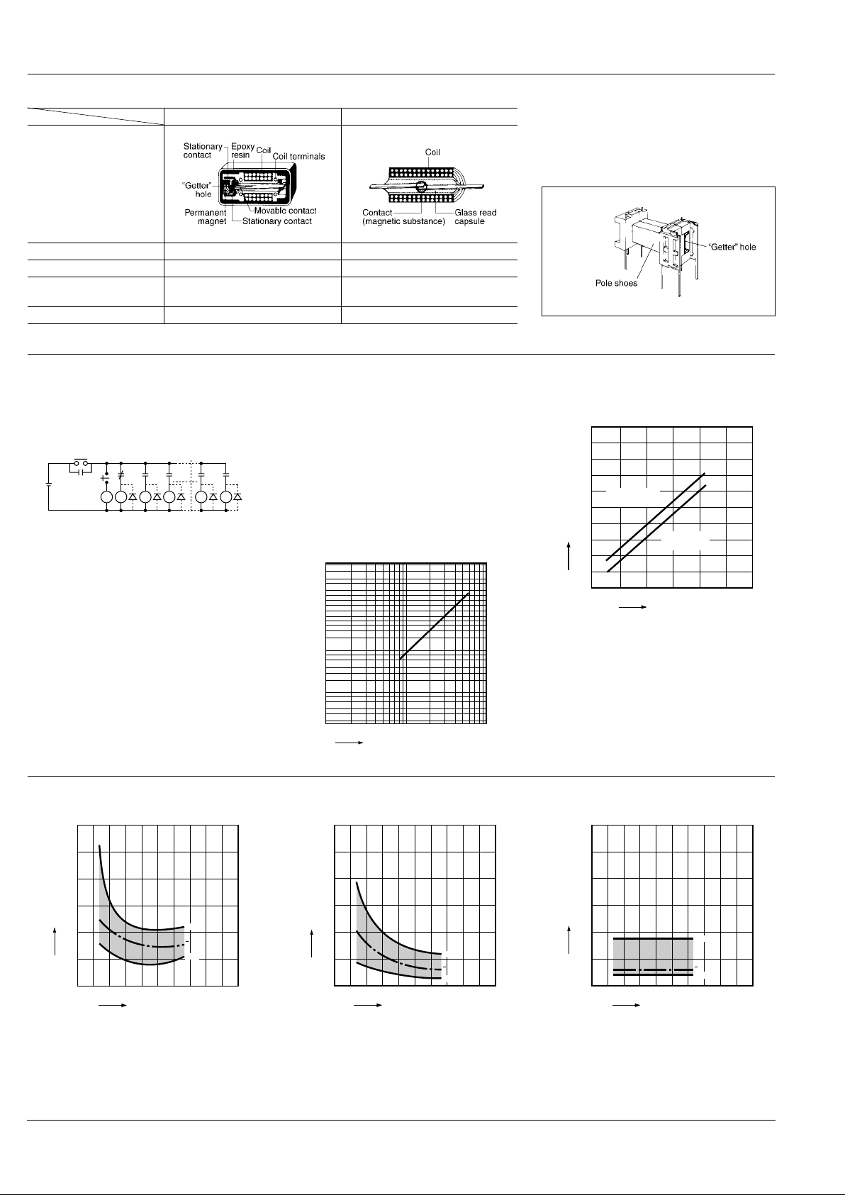
DIFFERENCES BETWEEN NR RELAYS AND REED RELAYS
NR relays Reed relays
Structure
Contact arrangement 1 Form C 1 Form A or 1 Form B
Contact capacity 20 W (high contact pressure) 5 to 15 W
Operating function
Single side stable
Latching
Single side stable
"Getter" hole Yes No
"Getter" holes are formed on both pole
shoes to obtain uniform contact resistance throughout life. Film-forming phenomena on contacts is thus fully
prevented.
REFERENCE DATA
1.-(1) Contact reliability
Test sample: NR-SD-24V 54 pcs.
Circuits: (A) Following figure with diode
(B) Following figure without diode
Item to be checked: Detect with the circuit stopped
Circuits:
(A) Diode provided: The circuit does not stop through-
out 100 million times.
(B) Diode not provided: λ
60
= 2.5 × 10
-8
times
1.-(2) Contact reliability
TEST CONDITION
Sample: NR-SD-24V, 10 pcs.
Contact voltage: 100 mV
Contact current: 10 µ A
Cycle rate: 50 cps.
Detection level: 100 Ω
Testing operation: 3 × 10
7
m = 1.9
σ
= 2.5 × 10
7
µ
= 4.7 × 10
7
95% reliability limit: 1.15 × 10
7
(Mean time between failure)
2. Coil temperature rise
(under saturated condition)
R0
R0
R54 R1 R2 R52 R53
R1 R2 R3 R53 R54
24 V DC
Stop
Start
1051
0.1
0.2
0.5
1.0
2.0
5.0
10.0
30.0
50.0
70.0
95.0
99.0
99.9
F(t)(%)
No. of operations, ×10
7
(WEIBULL)
100
250 500 750 1,000 1,250
90
80
70
60
50
40
30
20
10
Operating power, mW
Coil temperature rise, °C
Magnetically
sealed type
Plastic
sealed type
3.-(1) Operate time including bounce time
(Single side stable)
3.-(2) Operate time including bounce time
(2 coil latching)
4. Release time including bounce time
(Single side stable)
22018014010060
3.0
2.5
2.0
1.5
1.0
0.5
0
Min.
Max.
x
Coil applied voltage, %V
Operate time, ms
22018014010060
3.0
2.5
2.0
1.5
1.0
0.5
0
Min.
Max.
x
Coil applied voltage, %V
Operate time, ms
22018014010060
3.0
2.5
2.0
1.5
1.0
0.5
0
Min.
Max.
x
Coil applied voltage, %V
Release time, ms
Page 4

NR
115
5.-(1) Leaving at high temperature
(Change of pick-up and drop-out voltages)
Tested sample: NR-SD-24V, 30 pcs.
Condition: Deenergized leaving at 90 ° C 194 ° F
(constant temperature)
5.-(2) Leaving at high temperature
(Change of contact resistance)
Tested sample: NR-SD-24V, 30 pcs.
Condition: Deenergized leaving at 90 ° C 194 ° F
(constant temperature)
6. High frequency characteristics
Tested sample: NR-SD-24V
Tested condition:
500 1,000 1,500
8
4
12
10
6
2
20
18
16
14
Max.
Max.
Min.
Min.
Time, hr
Voltage, V
x
x
Pick-up voltage
Drop out voltage
100 1,000 10,000
50
100
500
1,000
Max.
Max.
Min.
Min.
Time, hr
Contact resistance, mΩ
N.C. side contact
N.O. side contact
A
SG(Signal generator)
N.C.
Frequency, MHz
Isolation loss between
A and B is measured.
Isolation, dB
N.O.
B
5 10 50 100
–50
–100
50Ω
50Ω
7. Contact sticking resistance
TEST CONDITION
The purpose of this test was to confirm contact sticking resistance and contact stability against coil ripples.
Tested Sample: NR-SD-24V, 10 pcs.
Test method: Following coil ripples were applied.
Test period: 500 hours
TEST RESULT
No occurance of sticking was observed.
Contact resistance: Fig. 1
NR-SD-24V: 29 m Ω to 30.4 m Ω
In actual application, above coil ripples should be
avoided and use of a capacitor in the circuit is recommended to keep the ripple factor below 5%.
8. Distribution of contact resistance
Tested sample: NR-SD-24V (WG type) 105 pcs.
7 V DC
100 Hz
24 V DC
10 100 1,000
50
100
Max.
Min.
x
Energization time, Hr Fig. 1
Contact resistance mΩ
10 20 30 40 50
10
20
30
40
50
Contact resistance, mΩ
Quantity
x = 24.2 mΩ
3σ = 9.27 mΩ
9.-(1) Rate of change in pick-up and drop-out
voltage (Single side stable)
9.-(2) Rate of change in pick-up voltage
(2 coil latching)
10.-(1) Mechanical life
(Change of pick-up and drop-out V)
Tested Sample: NR-SD-24V, 10 pcs.
Operation frequency: 500 cps
180
160
140
120
100
80
60
40
20
–40
–30
–20
–100102030405060708090
100
Ambient temperature, °C
Rate of change, %
Drop-out
voltage
Pick-up
voltage
180
160
140
120
100
80
60
40
20
–40
–30
–20
–100102030405060708090
100
Ambient temperature, °C
Rate of change, %
Pick-up
voltage
1,000 10,000 100,000
5
10
15
Min.
Max.
Min.
Max.
No. of operations, ×10
4
Pick-up/drop-out Voltage, V
Pick-up Voltage
Drop-out Voltage
10.-(2) Mechanical life
(Change of contact resistance)
Tested Sample: NR-SD-24V, 10 pcs.
Operation frequency: 500 cps
11.-(1) Electrical life
(1 A 20 V DC resistive load)
Tested sample: NR-SD-24V, 10 pcs.
11.-(2) Electrical life
Tested Sample: NR-SD-24V, 10 pcs.
Load: 60 mA 24 V DC resistive load
Frequency: 50 cps
1,000 10,000 100,000
50
40
30
20
10
60
70
80
90
Min.
Max.
No. of operations, ×10
4
Contact resistance, mΩ
N.C. side
N.O. side
1051
0.1
0.2
0.5
1.0
2.0
5.0
10.0
30.0
50.0
70.0
95.0
99.0
99.9
F(t)(%)
No. of operations, ×10
4
η: 1.85×10
6
µ: 1.65×10
6
σ: 5.64×10
4
(Weibull probability paper)
100 1,000 1,0000
50
100
150
No. of operations, ×10
4
Contact resistance, mΩ
N.C. side
N.O. side
Page 5

NR
116
11.-(3) Electrical life
Tested Sample: NR-SD-12V, 10 pcs.
Load: 54 mA 12 V DC inductive load
with diode protection
(4 relay coils in parallel of NR-SD-12V)
Frequency: 50 cps
11.-(4)Electrical life
(327 mA 24 V DC relay coil load)
Tested sample: NR-SD-24V, 5 pcs.
Condition: HP2-DC24×6 pcs. in parallel,
diode protector provided
1,000 10,000
100
1,000
Max.
Min.
No. of operations, ×10
4
Contact resistance, mΩ
100 200 300
8
4
0
12
16
Min.
Min.
Max.
Max.
x
x
No. of operations, ×10
4
Pick-up/drop-out voltage, V
Pick-up voltage
Drop-out voltage
L1 L2 L3
L4 L5 L6
100 200 300
80
100
40
20
60
x
Min.
No. of operations, ×10
4
Contact resistance, mΩ
24 V DC
NR relay contact
L1~L6: HP2-DC24V × 6 pcs. in parallel
Diode protector provided
Max.
12. Thermal electro motive force
Tested Sample: NR-SD-12V, 5 pcs.
Coil applied V: 12 V DC
Ambient atmosphere: 25°C 77°F, 60% RH
13. High temperature test
TEST CONDITION
Tested Sample: NR-SD-24V, 30 pcs.
Ambient temperature: 80°C 176°F
Humidity: less than 50% R.H.
Exposure time: 2,000 hours with relays deenergized.
TEST RESULT
Contact resistance: Fig. 1
All samples were measured less than
100 mΩ in contact resistance throughout this test.
14. Influence of adjacent mounting mm inch
15. Resistive load test
TEST CONDITION
Tested Sample: NR-SD-24V, 10 pcs.
Load: 1 A 20 V DC Resistive
Cycle rate: 1.4 cps.
Contact resistance in life test
2 4 6 8 10 12 14 16
100
200
Hour
Thermal EMF, µV
N.C.
N.O.
10
20
40
60
80
100
100
1,000 2,000
Exposure time, hr
Contact resistance, mΩ
Max.
Max.
Min.
Distance
0
(0)5(.197)10(.394)15(.591)
Type
Magnetically
shielded type
±5% ±1% 0 0
Sealed type — ±10% ±6% ±2%
No. of operations, ×10
6
1
20
50
100
500
N.C.
Max.
Max.
Mean value
of N.O.
Mean value
of N.C.
Min.
Min.
N.O.
2 5 10 15
Contact resistance, mΩ
APPLICATION HINTS
Contact protection circuit
When using NR relays in inductive load circuits, a contact protection circuit is recommended.
Examples:
CR CR Diode
1. r = more than 20 to 30 ohms
2. In an AC circuit impedance of L is to be
somewhat smaller than impedance of r
and c.
Can be used for both AC and DC circuits.
Use 500 to 1000 ohms for r and 0.1 µF to
0.2 µF 200 V for c in a general 12 to 24 V
load circuit.
For DC circuits only.
S
Relay contact
: Inductive load
rc
L
L
r
S
c
L
S
L
Page 6

NR
117
The following is life data under our HP2 relay load.
(Notes)
1. When inrush current occurs in the capacitor load circuit or incandescent lamp load circuit, reduce it to less than 5 A. Electrical life of "AuCo" contact
types is 10,000 operations in a 5 A inrush current circuit.
2. When 5 A to 10 A inrush current occurs in the capacitor load circuit or incandescent lamp load circuit, the use of power types is recommended.
Contact voltage Contact current Contact protection circuit Operating speed Expected life, min. op.
6 V DC 232 mA 0.2 µF + 1kΩ or diode 2 op./s 3×10
7
12 V DC 106 mA 0.2 µF + 1kΩ or diode 2 op./s 3×10
7
24 V DC 54 mA 0.1 µF + 1kΩ or diode 2 op./s 3×10
7
100 V DC 15 mA 0.1 µF + 1kΩ or diode 2 op./s 2×10
7
24 V DC 80 mA 0.2 µF + 1kΩ 2 op./s 3×10
7
100 V DC 20 mA 0.1 µF + 1kΩ or varistor 2 op./s 2×10
7
200 V DC 10 mA 0.1 µF + 1kΩ 2 op./s 2×10
7
2 coil latching types
A) The circuit at right is recommended
when using one coil for latching and the
other coil for reset.
NR relays are sensitive enough to be operated by the discharge of energy accumulated in the inner-coil capacitance. The
use of a diode of over 200 V breakdown
will prevent misoperation from this source .
In order to maintain the insulation between the two coils, connection of the terminal No. 3 and No. 6 or the terminal No.
2 and No. 5 is recommended, as shown in
the right figure.
Rectifiers should be inserted in this circuit
when the nominal coil voltage of the NR
relay is more than 24 V DC.
B) No damage will occur to the coil of either the one or two coil latching types
even if the operating voltage is as much
as 2 or 3 times the nominal coil voltage.
C) If separate pulses are applied to each
coil of the 2 coil latching types, the first
pulse will operate when the pulses are of
equal voltage. When voltages differ the
higher voltage will cause operation provided the voltage difference is greater
than the measured pick-up voltage. Voltage difference on the coils will reduce
contact pressure proportionately.
Continuous bias voltage after an operating pulse lowers contact pressure and vibration resistance.
bias voltage
coil
coil
Ripple factor
Coils should be operated on pure DC.
Rectified AC may cause changes in the
pick-up/drop-out characteristics because
of the ripple factor. Use of a capacitor in
the circuit is recommended to keep the
ripple factor below 5%.
: relay
E min. E max. E mean DC component
Pulsating component
capacitor (ripple filter)
R
R
To calculate the ripple factor
Ripple factor (%) = × 100%
E max. = max. value of pulsating component
E min. = min. value of pulsating component
E mean - average value DC component
E max. – E min.
E mean
When designing NR relay circuits
Care should be taken when designing relay circuits since the response of the relay
is so fast that bouncing or chattering from
conventional relays in the circuit may
cause false operation.
When using long lead wires
When long wires (as long as 100 m or
more) are to be used, the use of resistance (10 to 50 Ω) in series with the contact is required in order to eliminate the
effect of the possible inrush current due to
the stray capacitance existing between
the two wires or between the wire and
ground.
Contact of NR relay
Lead wire
+
Energy accumulated in
static capacitance
(100 to 300 m)
10 to 50 Ω
(Equivalent circuit)
Page 7

NR
118
AC operation of latching relays
When using circuits such as those at the
right, avoid continued or extended latching or resetting power input.
Latching
switch
1 coil bistable type
Reset
switch
Latching
switch
2 coil bistable type
Reset
switch
2
5
36
Capacitor discharge operation of latching types
When operating latching types by discharge of a capacitor, more reliable operation can be expected if the time to reach
pick-up voltage is greater than 2 ms at 5
to 10 µF: (24 V type).
NR relay
coil
Specified
Pick-up voltage
more than 2 ms
t
(V)
SW
C
Flicker circuit
NR relay contact
CC
5
6
2
3
Automatic coil circuit interruption
Misoperation may occur in self-operated
cutoff circuits such as shown at right. This
can be avoided by adding a resistor and
capacitor and increasing the pick-up voltage to above that specified.
In a timer circuit, step-pulse voltage from
PUT (Programmable Unijunction Transistor) or SBS (Silicon Bilateral Switch) is
recommended.
NR relay contact
NR relay coil
SW
NR relay coil
Coil voltage wave form
V
T
(Time)
Residual voltage
When single side stable types or latching
types are driven by transistor or UJT, residual voltage is sometimes applied to the
coils and decreases contact pressure at
N.O. side e v en if the transistor or UJT are
in OFF condition. As a result, characteris-
tics of relays may be harmed. Design your
circuits in principle to make such residual
voltage zero.
Short circuit prevention between N.C. and N.O.
The separation of loads or insertion of a
resistor for circuit protection are recommended for the circuits where large current flows due to arcing. (See Fig. 1).
Fig. 1
COM
N.C.
N.O.
Load
COM
N.C.
N.O.
Load
Load separation
Load
Page 8

NR
119
ACCESSORIES
PC board terminal sockets (with hold-down clip)
R-PS
Terminal width: 1.3 .051
Terminal thickness: 1.2 .047
General tolerance: ±0.5 ±.020
10
.394
9.9
.390
6.15
.242
0.3
.012
20.9
.823
1
4
2
7
6
3
E
5
PC board pattern (Copper-side view)
Tolerance: ±0.2 ±.008
5.0
.197
8-1.5 to 1.6 dia.
8-.059 to .063 dia.
2.4
.094
2.7
.106
7.4
.291
4.4
.173
mm inch
For Cautions for Use, see Relay Technical Information (Page 48 to 76).
9/1/2000 All Rights Reserved, © Copyright Matsushita Electric Works, Ltd.
Go To Online Catalog
 Loading...