

Page 1

NMF480-1 480MHz SAW Filter
Approved by:
Checked by:
Issued by:
SPECIFICATION
PRODUCT: SAW FILTER
MODEL: NMF 480-1 TO-39
HOPE MICROELECTRONICS CO.,LIMITED
Tel:+86-755-82973806 Fax:+86-755-82973550 E-mail: [email protected] http://www.hoperf.com
Page 1 of 3
Page 2
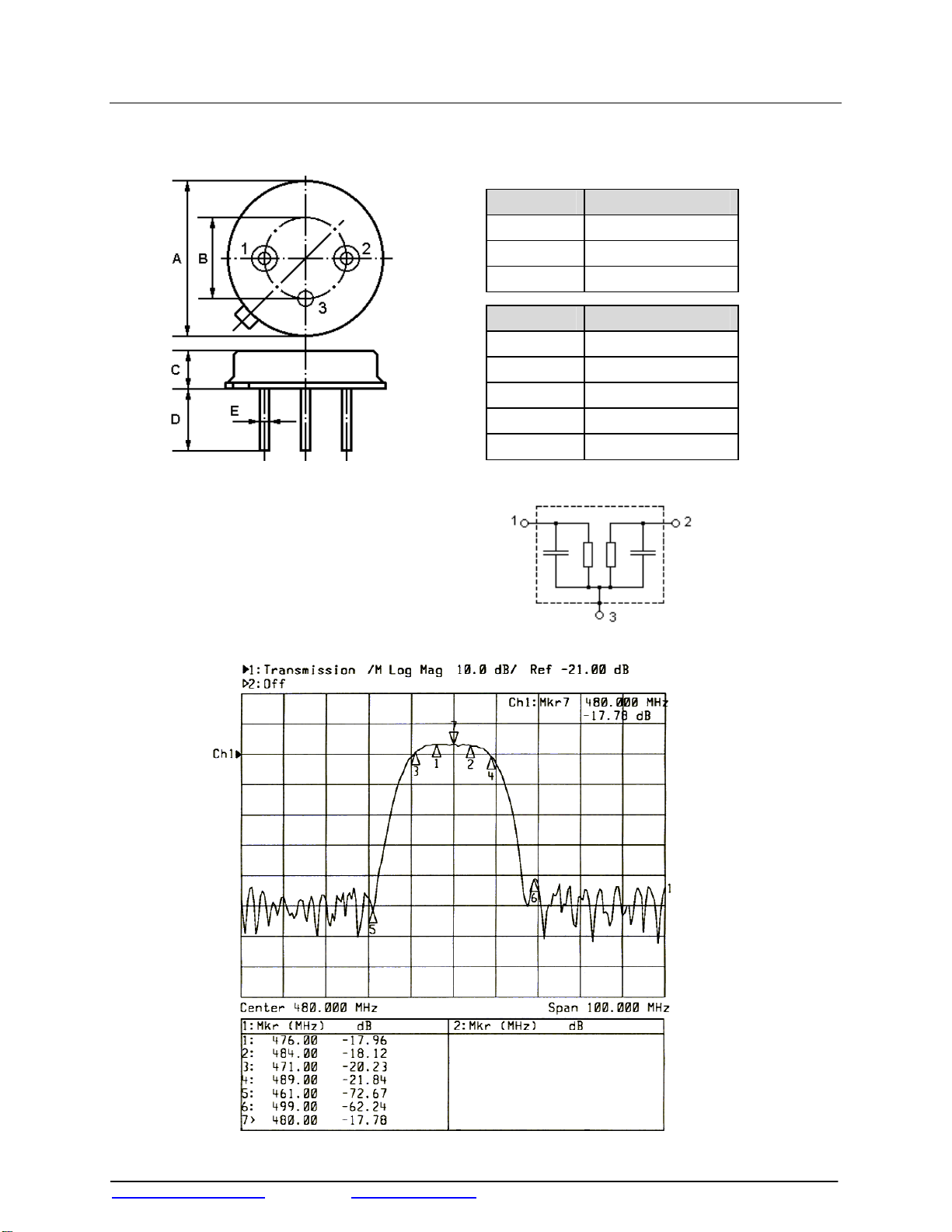
SAW Filter NMF480-1
The NMF480-1 is an IF filter for DBS receivers with constant group delay.
1.Package Dimension (TO-39)
Pin Configuration
1 Input / Output
2.Marking 3.Equivalent LC Model
2 Output / Input
3 Case Ground
Dimensions Data (Unit: mm)
A 9.35±0.10
B 5.08±0.10
C 3.40±0.10
D 3.00±0.20
E Φ0.45±0.20
NMF480-1
Color: Black or Blue
4.Typical Frequency Response
Tel:+86-755-82973806 Fax:+86-755-82973550 E-mail: [email protected] http://www.hoperf.com
Page 3
SAW Filter NMF480-1
τ
τ
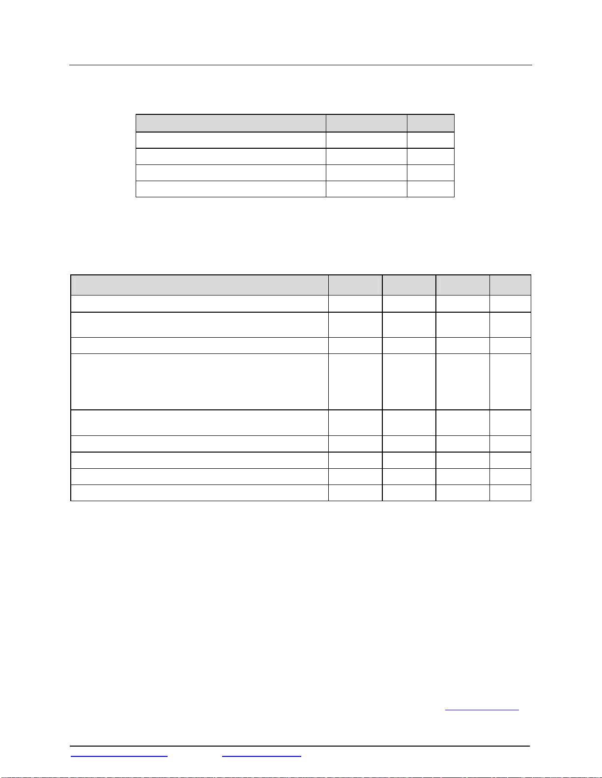
5.Performance
5-1.Maximum Ratings
Rating Value Units
AC Voltage Between Any Two Pins Vpp 5 V
DC Voltage Between Any Two Pins V
Storage temperature range T
Operable temperature range TA -25 to +85 ℃
DC
-40 to +85 ℃
stg
5-2.Electronic Characteristics
Reference temperature: T
= 25 ℃
A
Terminating source impedance: ZS = 50 Ω
Terminating load impedance:
ZL = 50 Ω
Characteristic Min. Typ. Max. Units
Center Frequency f
Insertion attenuation 480.00 MHz
(Reference level for the following data)
Pass bandwidth α
Relative attenuation α
Lower sidelobe 430.00 ….461.00 MHz
Upper sidelobe 499.00 … 530.00 MHz
Reflected wave signal suppression
0.13µs … 2.0µs after main pulse
Amplitude ripple (p-p) 476.00 … 484.00 MHz ∆ α
Group delay (aperture 0.25MHz) 480.00 MHz
Group delay ripple (p-p) 471.50 … 488.50 MHz ∆
Temperature coefficient of frequency TC
≤3dB B
rel
471.00 MHz
489.00 MHz
C
α
3dB
rel
f
LCAUTION: Electrostatic Sensitive Device. Observe precautions for handling!
C 2003. All Rights Reserved.
○
1. The frequency fC is defined as the midpoint between the 3dB frequencies.
2. Unless noted otherwise, all measurements are made with the filter installed in the specified test fixture that is
connected to a 50Ω test system with VSWR≤1.2:1. The test fixture L and C are adjusted for minimum insertion
loss at the filter center frequency, f
the impedance matching component values and quality.
3. Unless noted otherwise, specifications apply over the entire specified operating temperature range.
4. The specifications of this device are based on the test circuit shown above and subject to change or
obsolescence without notice.
5. All equipment designs utilizing this product must be approved by the appropriate government agency prior to
manufacture or sale.
6. Our liability is only assumed for the Surface Acoustic Wave (SAW) component(s) per se, not for applications,
processes and circuits implemented within components or assemblies.
7. For questions on technology, prices and delivery, please contact our sales offices or e-mail sales@hoperf.com
. Note that insertion loss, bandwidth, and passband shape are dependent on
C
0 V
479.00 480.00 481.00 MHz
-- 21 23.0 dB
16.60 17.80 18.60 MHz
--
--
38.0
38.0
40.0 46.0 -- dB
-- 0.6 1.0 dB
-- 281.0 -- ns
-- 11.5 18.0 ns
-- -94 -- ppm/K
3.4
3.0
50.0
45.0
5.4
5.4
--
--
dB
dB
dB
dB
.
Tel:+86-755-82973806 Fax:+86-755-82973550 E-mail: [email protected] http://www.hoperf.com
 Loading...