

Page 1

NJU6475B
PRELIMINARY
12-Character 4-Line Dot Matrix Low Power
LCD Controller Driver with key Scan Function
GENERAL DESCRIPTION PACKAGE OUTLINE
The NJU6475B is a Dot Matrix LCD Controller Driver for
12-character 4-line with Icon display in single chip. It contains
voltage converter, voltage regulator, bleeder resistance, CR
oscillator, instruction decoder, character generator ROM/RAM,
high voltage operation controller/driver and key scan circuit.
The voltage converter generates (about 8V) from the
supply voltage (3V) and regulated by the regulator. The bias
level of LCD driving voltage is generated of high value bleeder
resistance and the buffer amplifier matches the
impedance. 16-step contrast control function is incorporated
for its adjustment. Therefore, simple power supply circuit and NJU6475B
easy contrast adjustment are available. The complete CR
oscillator is incorporated without external components for
oscillation circuit. The microprocessor interface circuit w hich
operates by 1MHz, can be selected serial interface.
The character generator ROM consisting of 10,080bits stores
252 kinds of character Font.
Each 160bits CG RAM and Icon display RAM can story
4 kinds of special character to display on the dot matrix
display area or 128 kinds of Icon on the display area.
FEATURES
12-Character 4-Line Dot Matrix LCD Controller Driver
•
Maximum 128-Icon Display
•
Serial CPU Interface
•
Display Data RAM - 48 x 8 Bits :Maximum 12-Character 4-Line Display
•
Character Generator ROM - 10,080 Bits:252 Characters (5 x 8 Dots)
•
Character Generator RAM - 32 x 5 Bits :4 Patterns (5 x 8 Dots)
•
Icon Display RAM - 32 x 5 Bits :Maximum 128-Icon
•
High Voltage LCD Driver : 37-Common/63-Segment
•
Duty & Bias Ratio : 1/36 duty 1/7Bias
•
Useful Instruction Set : Clear Display, Return Home, Display On/Off Control
•
Common and Segment Driver location Order Select Function (Mode-A, Mode-B)
•
Power On Reset Circuit On Chip
•
Hardware Reset
•
Voltage Regulator On Chip
•
Electrical Variable Resistance On Chip
•
32-key scan function (8 x 4 Matrix)
•
Oscillation circuit On Chip
•
Voltage Converter (Doubler,Tripler) On Chip
•
Bleeder Resistance On Chip
•
Low Oprating Current
•
Operating Voltage - 2.4V to 3.6V (Except For LCD Driving Voltage)
•
Package Outline - Bumped-Chip / TCP
•
C-MOS Technology
•
Display Blink,Cursor Shift, Character Shift
Page 2

NJU6475B
PAD LOCATION
Page 3

NJU6475B
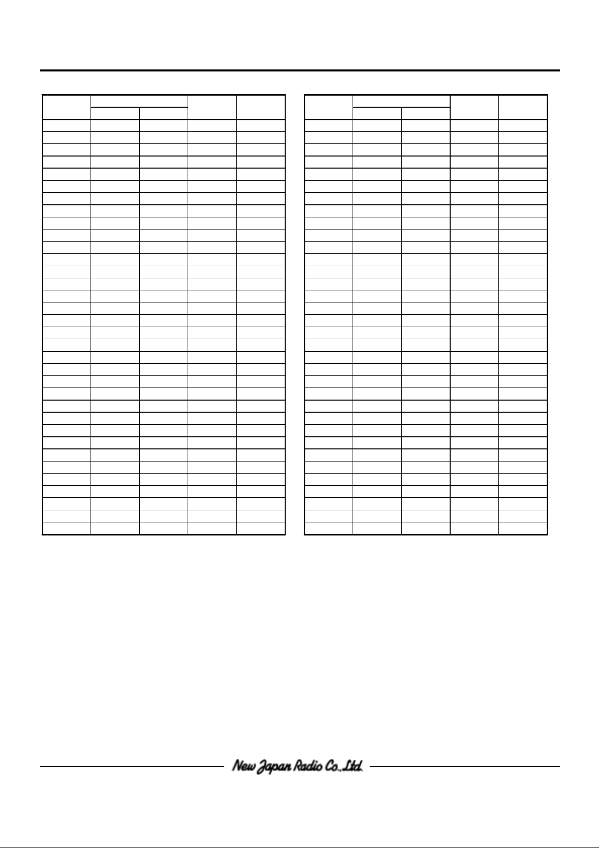
PAD COORDINATES
Chip Size 11.22×2.5mm (Chip Center X=0um,Y=0um)
PAD No. PAD No.
PAD Name PAD Name
Mode A Mode B Mode A Mode B
1 ALI-A1 ALI-A1 -6240 -1090 51 NC NC 5817 1090
2 OSC OSC -6020 -1090 52 NC NC 5617 1090
3 OSC OSC -5775 -1090 53 NC NC 5417 1090
4 V V -5479 -1090 54 NC NC 5217 1090
5 V V -4979 -1090 55 NC NC 5017 1090
6 V V -4479 -1090 56 NC NC 4817 1090
7 C2 C2 -3979 -1090 57 NC NC 4617 1090
8 C2 C2 -3479 -1090 58 NC NC 4417 1090
9 C1 C1 -2979 -1090 59 NC NC 4217 1090
10 C1 C1 -2479 -1090 60 NC NC 4017 1090
11 V V -1979 -1090 61 NC NC 3817 1090
11
22
55
SS SS
5OUT 5OUT
--
++
--
++
DD DD
12 VR VR -1479 -1090 62 NC NC 3617 1090
13 V V - 979 -1090 63 NC NC 3417 1090
REG REG
14 TEST TEST - 531 -1090 64 SEGS SEGS 3160 1090
15 SEL SEL - 302 -1090 65 COM COM 2780 1090
16 - 74 -1090 66 COM COM 2700 1090
RESET RESET
17 P/S P/S 155 -1090 67 COM COM 2620 1090
18 RS RS 383 -1090 68 COM COM 2540 1090
19 R/W R/W 612 -1090 69 COM COM 2460 1090
20 E/SCL E/SCL 840 -1090 70 COM COM 2380 1090
21 1069 -1090 71 COM COM 2300 1090
LCD/KEY LCD/KEY
22 REQ REQ 1298 -1090 72 COM COM 2220 1090
23 DB /CS DB /CS 1536 -1090 73 COM COM 2140 1090
24 1773 -1090 74 COM COM 2060 1090
25 DB DB 2010 -1090 75 COM COM 1980 1090
26 DB DB 2247 -1090 76 COM COM 1900 1090
27 DB DB 2484 -1090 77 COM COM 1820 1090
28 DB DB 2721 -1090 78 COM COM 1740 1090
29 DB DB 2958 -1090 79 COM COM 1660 1090
30 DB DB 3195 -1090 80 COM COM 1580 1090
31 K K 3466 -1090 81 SEGM SEGM 1500 1090
32 K K 3632 -1090 82 SEG SEG 1420 1090
33 K K 3903 -1090 83 SEG SEG 1340 1090
34 K K 4068 -1090 84 SEG SEG 1260 1090
35 S S 4244 -1090 85 SEG SEG 1180 1090
36 S S 4352 -1090 86 SEG SEG 1100 1090
37 S S 4460 -1090 87 SEG SEG 1020 1090
38 S S 4568 -1090 88 SEG SEG 940 1090
39 S S 4676 -1090 89 SEG SEG 860 1090
40 S S 4784 -1090 90 SEG SEG 780 1090
41 S S 4892 -1090 91 SEG SEG 700 1090
42 S S 5000 -1090 92 SEG SEG 620 1090
77 25 25
66
DB /SIO DB /SIO
55 27 27
44 28 28
33 29 29
22 30 30
11 31 31
00 32 32
00 12
11 160
22 259
33 358
00 457
11 556
22 655
33 754
44 853
55 952
66 10 51
77 11 50
43 NC NC 5217 -1090 93 SEG SEG 540 1090
44 NC NC 5417 -1090 94 SEG SEG 460 1090
45 NC NC 5617 -1090 95 SEG SEG 380 1090
46 NC NC 5817 -1090 96 SEG SEG 300 1090
47 NC NC 6017 -1090 97 SEG SEG 220 1090
48 ALI-A2 ALI-A2 6217 -1090 98 SEG SEG 140 1090
49 ALI-B2 ALI-B2 6217 1090 99 SEG SEG 60 1090
50 NC NC 6017 1090 100 SEG SEG - 20 1090
X=(um) Y=(um) X=(um) Y=(um)
11
99
10 10
11 11
12 12
13 13
14 14
15 15
16 16
26 26
12 49
13 48
14 47
15 46
16 45
17 44
18 43
19 42
Page 4
NJU6475B
PAD No. PAD No.
101 SEG SEG - 100 1090 135 SEG SEG -2820 1090
102 SEG SEG - 180 1090 136 SEG SEG -2900 1090
103 SEG SEG - 260 1090 137 SEG SEG -2980 1090
104 SEG SEG - 340 1090 138 SEG SEG -3060 1090
105 SEG SEG - 420 1090 139 SEG SEG -3140 1090
106 SEG SEG - 500 1090 140 SEG SEG -3220 1090
107 SEG SEG - 580 1090 141 SEG SEG -3300 1090
108 SEG SEG - 660 1090 142 SEGM SEGM -3380 1090
109 SEG SEG - 740 1090 143 COM COM -3460 1090
110 SEG SEG - 820 1090 144 COM COM -3540 1090
111 SEG SEG - 900 1090 145 COM COM -3620 1090
112 SEG SEG - 980 1090 146 COM COM -3700 1090
113 SEG SEG -1060 1090 147 COM COM -3780 1090
114 SEG SEG -1140 1090 148 COM COM -3860 1090
115 SEG SEG -1220 1090 149 COM COM -3940 1090
116 SEG SEG -1300 1090 150 COM COM -4020 1090
117 SEG SEG -1380 1090 151 COM COM -4100 1090
118 SEG SEG -1460 1090 152 COM COM -4180 1090
119 SEG SEG -1540 1090 153 COM COM -4260 1090
120 SEG SEG -1620 1090 154 COM COM -4340 1090
121 SEG SEG -1700 1090 155 COM COM -4420 1090
122 SEG SEG -1780 1090 156 COM COM -4500 1090
123 SEG SEG -1860 1090 157 COM COM -4580 1090
124 SEG SEG -1940 1090 158 COM COM -4660 1090
125 SEG SEG -2020 1090 159 COMM COMM -4740 1090
126 SEG SEG -2100 1090 160 COMM COMM -4820 1090
127 SEG SEG -2180 1090 161 COMM COMM -4900 1090
128 SEG SEG -2260 1090 162 COMM COMM -4980 1090
129 SEG SEG -2340 1090 163 COMS COMS -5085 1090
130 SEG SEG -2420 1090 164 NC NC -5285 1090
131 SEG SEG -2500 1090 165 NC NC -5485 1090
132 SEG SEG -2580 1090 167 NC NC -5885 1090
133 SEG SEG -2660 1090 168 NC NC -6085 1090
134 SEG SEG -2740 1090 169 ALI-B2 ALI-B2 -6240 1090
PAD Name PAD Name
Mode A Mode B Mode A Mode B
20 41 54 7
21 40 55 6
22 39 56 5
23 38 57 4
24 37 58 3
25 36 59 2
26 35 60 1
27 34 21
28 33 24 24
29 32 23 23
30 31 22 22
31 30 21 21
32 29 20 20
33 28 19 19
34 27 18 18
35 26 17 17
36 25 88
37 24 77
38 23 66
39 22 55
40 21 44
41 20 33
42 19 22
43 18 11
44 17 44
45 16 33
46 15 22
47 14 11
48 13 11
49 12
50 11
51 10
52 9
53 8
X=(um) Y=(um) X=(um) Y=(um)
Page 5

BLOCK DIAGRAM
NJU6475B
Page 6

NJU6475B
TERMINAL DESCRIPTION
PAD No. Symbol I/O F u n c t i o n
11,5 V ,V - P ower Source : V =+3V GND : V =0V
4 V - LCD driving voltage
2,3 OSC , I/O System clock terminal
DD SS DD SS
5
1
2
OSC Oscillation C and R are incorporated. (Normally Open)
For external clock operation, the clock should be input on OSC .
17 P/S I Serial input select terminal (fixed to "L")
Register selection signal input terminal
18 RS I "0" instruction r egister. (Writing)
"1" Data register. (Writing, Reading)
19 R/W I Read(R) / Write(W) selection signal input terminal
20 E/SCL I Serial clock input terminal
23 DB /CS I Chip select signal
24 DB /SIO I/O Data input terminal (3-state data bus.)
25 - 30 DB - DB I I/O port output terminal
7
6
05
1
22 REQ O This terminal normally output "L".
When confirm a key action, REQ terminal output puls.
21 LCD/KEY I Fix to "H" Level
35 - 42 S -S O Key scan signal data output terminal
o7
Open Drain Output
31 - 34 K - K I Key scan data input terminal
03
In case of non use, fix to "H".
158 - 151 COM - COM O Common signal output terminal
132
65 - 72
150 - 143
73 - 80
162 - 159 COMM - O Icon common display signal output terminal
163 COMS O Static driving common signal output terminal
82 - 141 SEG - SEG O Segment signal output terminal
1
COMM
160
4
1
When power down mode V or V levels are output.
DD SS
81,142 SEGM ,SEGM O Icon segment driving signal output terminal
12
Page 7

PAD No. Symbol I/O F u n c t i o n
NJU6475B
57 SEGS O Static driving segment signal output terminal
10,9 C1 C1 I/O Step up voltage capacitor connecting terminal
8,7 C2 ,C2
6 V O Step up voltage output terminal
13 V O Voltage regulator output terminal
1
+-
+-
5OUT
REG
When power down mode V or V level are output.
DD SS
Connect the resistor between this terminal and VR terminal.
12 VR I Reference voltage for voltage regulator input terminal
Connect the resistor between this reference voltage and
DD
V terminal.
Reset terminal
16 RESET I When the "L" level input over than 1.2ms to this terminal,
the system is reset (at f =180KHz).
osc
Common and Segment driver location order select terminal.
15 SEL I "0" Mode A location (See PAD COORDINATES)
"1" Mode B location (See PAD COORDINATES)
14 TEST I Maker test terminal
This terminal should be connected to V (or open.)
SS
43 - 47 NC - Non connection terminal
50 - 63
These terminals are electrically open.
164 - 168
169 ALI-A1 Alignment mark
49 ALI-A2 - These terminals are electrically open.
1ALI-B1
48 ALI-B2
Page 8

NJU6475B
FUNCTIONAL DESCRIPTION
(1) Description for each blocks
(1-1) Register
The NJU6475B incorporates three 8-bit registers, an instruction register (IR), and a Data Register (DR), Key
Register (KR). The register (IR) stores an instruction code such as "clear display" and "cursor shift" or address
data for Display Data RAM (DD RAM), Character Generator RAM (CG RAM) and Icon Display RAM (MK RAM).
The MPU can write the instruction code and address data to the register (IR), but it cannot read out from
register (IR). The Register (DR) is a temporary register, the data stored in the Register (DR) is written into
DD RAM, MK RAM. A register from these two registers is selected by the register select signal (RS). Register
(KR) is an only temporary register for key scan data. This Register (KR) can read out the contents when
selected Key signal at "H" signal. And non relation ship with signal of register select (RS).
The Relation ship with RS, R/W register as shown below.
<Table-1> Register selection
RS R/W O p e r a t i o n
0 0 IR write & internal register operation mode
0 1 Read out (KR)
1 0 Write (DR) & internal register operation mode
1 1 Read out (KR)
(Clear Display etc...)
(DR DD RAM/CG RAM/MK RAM)
(1-2) Address Counter (AC)
The address counter (AC) addresses the DD RAM, CG RAM or MK RAM. When the address setting instruction is written into register (IR), the address information is transferred from register (IR) to the address counter
(AC). The selection of DD RAM, CG RAM or MK RAM is also determined by this instruction.
After writing (or reading) the display data to (or from) the DD RAM, CG RAM or MK RAM, the address counter
(AC) increments (or decrements) automatically.
(1-3) Display Data RAM (DD RAM)
The display data RAM (DD RAM) consisting of 48 x 8 bits stores up to 48-character display data represented
in 8-bit code.
The DD RAM address data set in the address counter (AC) is represented in Hexadecimal code.
(Example) DD RAM Address "08"
upper order bit lower order bit
ACACACACACACACAC 0 001000
6543210
hexadecimal hexadecimal 0 8
Page 9

(1-3-1) The relation between DD RAM address and display position on the LCD
12-Characters 4-Line Display
-
123 4567 89101112 DisplayPosition
1stLine000102030405060708090A0B DDRAMAddress
2ndLine101112131415161718191A1B
3rdLine202122232425262728292A2B
4thLine303132333435363738393A3B
When the display shift is performed, the DD RAM address changes as follows:
[Left shift display]
(00) 01 02 03 04 05 06 07 08 09 0A 0B 00
NJU6475B
(Hexadecimal)
(10) 11 12 13 14 15 16 17 18 19 1A 1B 10
(20) 21 22 23 24 25 26 27 28 29 2A 2B 20
(30) 31 32 33 34 35 36 37 38 39 3A 3B 30
[Right shift display]
0B 00 01 02 03 04 05 06 07 08 09 0A (0B)
1B 10 11 12 13 14 15 16 17 18 19 1A (1B)
2B 20 21 22 23 24 25 26 27 28 29 2A (2B)
3B 30 31 32 33 34 35 36 37 38 39 3A (3B)
(1-4) Character Generator ROM (CG ROM)
The Character Generator ROM (CG ROM) stores 5 x 8 dots character pattern represented in 8-bit character
code. The capacity is up to 252 kinds of 5 x 8 dots character pattern.
The correspondence between character code and standard character pattern of NJU6475B is shown in table 2.
User defined character patterns (Custom Font) are also available by mask option. (in this case, the address
H
(20) are using for "Space Pattern".)
Page 10

NJU6475B
<Table-2> The Correspondence Between Character Code
and Standard Character Pattern (ROM Version -02)
Page 11

NJU6475B
(1-5) Character Generator RAM (CG RAM)
The Character Generator RAM stores any kinds of character pattern in 5 x 8 dots written by the user
program to display user's original character pattern. The CG RAM can store 4 kinds of character in 5 x 8 dots
mode.
To display user's original character pattern stored in the CG RAM, the address data (00) -(03) should
be written to the DD RAM as shown in Table-3.
Table-3> Correspondence of CG RAM address, DD RAM character code
<
and CG RAM character pattern (5 x 8 dots)
HH
Character Code Character Pattern
(DD RAM Data) (CG RAM Data)
76543210 76543 210 43210
Upper Lower
Bits Bits Upper Lower Upper Lower
00000000 01000 100 0 0011
00000011 01011
CG RAM Address
000 01111
11001 000
010 000 CharacterPattern11
011 0 Example(1)1111
101 00 011
11110 000
111 00000 CursorPosition
11000 000
001 0 0 011
0 1 0 Character Pattern11111
011 00 00 Example(2)1
1111100000001 01001 100
101 00 001
110 00 001
111 00000 CursorPosition
000
001
100
101
110
111
Notes : 1. Character code bit 0,1 correspond to the CG RAM address bit 3,4 (2bits ; 4patterns).
2. CG RAM address 0 to 2 designate character pattern line position. The 8th line should be "0".
If there is "1" in the 8th line, but bit "1" is always displayed on the cursor position regardless of cursor
existence.
3. Row position character pattern correspond to CG RAM data bits 0 to 4 are shown above.
4. CG RAM character patterns are selected when character code bits 2 to 7 are all "0" and these are
addressed by character code bits "0" and "1".
5. "1" for CG RAM data corresponds to display on and "0" to display off.
Page 12

NJU6475B
(1-6) Icon display RAM (MK RAM)
The NJU6475B can display maximum 128 Icons.
The Icon display can be controlled by writing the data into MK RAM corresponding to the Icons.
The relation between MK RAM address and Icon display position is shown in Table-4.
Table-4> Correspondence among Icon Position, MK RAM Address and Data
<
MK RAM Address Bits for Icon Position MK RAM Address and Data
HH 76543210
(60-7F) DDDDDDDD
0110000060 ***123497
0110000161 ***567898 COMMLineand
0110010165 ***21222324102
0110011066 *******103 (COM,COM,COM,COM)
0110011167 *******104
0110100068 ***25262728105
0110100169 ***29303132106 COMMLineand
011011016D***45464748110
011011106E*******111 (COM,COM,COM,COM)
011011116F*******112
0111000070 ***49505152113
0111000171 ***53545556114 COMMLineand
0111010175 ***69707172118
0111011076 *******119 (COM,COM,COM,COM)
0111011177 *******120
0111100078 ***73747576121
0111100179 ***77787980122 COMMLineand
011111017D***93949596126
011111107E*******127 (COM,COM,COM,COM)
011111117F*******128
H
H 1
H
H 1357
H
H
H 2
H
H 9111315
H
H
H 3
H
H 17 19 21 23
H
H
H 4
H
H 25 27 29 31
H
Both besides of 1st Line
Both besides of 2nd Line
Both besides of 3rd Line
Both besides of 4th Line
Notes : 1. When the Icon display function using, the system should be initialized by the software initialization
Because the MK RAM is not initialized by the power on reset and hardware.
2. The cross-points between segments (SEGM and SEGM ) and commons (COMM to COMM and
232
COM to COM ) are always set "OFF" level.
12 14
3. In the table 4, * mark are invalid, therefore both of "0" or "1" can be written but these are no meaning.
Page 13

NJU6475B
(1-7) Timing generator
The timing generator generates a timing signals for the DD RAM, CG RAM and MK RAM and other
internal circuits. RAM and timing for the display and internal operation timing for MPU access are separately
generated, so that may not interfere with each other.
Therefore, when the data write to the DD RAM for example, there will be undesirable influence, such as
flickering, in areas other than display area.
(1-8) LCD Driver
LCD Driver consists of 37-common driver and 63-segment driver. The character pattern data are latched
to the addressed segment-register respectively.
This latched data controls display driver to output LCD driving waveform.
(1-9) Cursor Blinking control circuit
This circuit controls cursor On / Off and cursor position character blinking. The cursor or blinking appear in
the digit locating at the DD RAM address set in the address counter (AC). When the address counter is (08) ,
a cursor position is shown as bellow.
6543210
AC AC AC AC AC AC AC
AC0001000
H
4-Line Display
1 2 3 4 5 6 7 8 9 10 11 12 Display position
1stLine000102030405060708090A0B DDRAMAddress
(Hexadecimal)
2nd Line 10 11 12 13 14 15 16 17 18 19 1A 1B
3rdLine202122232425262728292A2B
4thLine303132333435363738393A3B
Cursor position
Note : The cursor or blinking also appear when the address counter (AC) selects the CG RAM or the MK RAM.
But the displayed cursor and blinking are meaningless.
If the AC stores the CG or MK RAM address data, the cursor and blinking are displayed in the meaningless position.
Page 14

NJU6475B
(2) Power on Initialization by internal circuits
(2-1) Internal Reset circuits Initialization
The NJU6475B is automatically initialized by internal power on initialization circuits when the power is turned
on. In the internal power on initialization, following instructions are executed.
During the Internal power on initialization, the busy flag (BF) is "1" and this status is kept during 6ms
OSC DD
(f =180KHz) after V rose to 2.4V.
Initialization sequence
Set Function PD=1 : Power down OFF
Contrast Control Set (00) to the contrast register
H
Display ON/OFF D=0 : Display OFF
Control C=0 : Cursor OFF
B=0 : Cursor Blink OFF
I/D=1 : Increment by 1
Set Mode Entry S=0 : Non shift
Clear Display
END
Note : If the condition of power supply rise time described in the Electrical Characteristics is not satisfied, the
internal Power On Initialization will not performed.
In this case, the software initialization by MPU is required.
(2-2) Hardware Initialization
The NJU6475B prepares RESET terminal to initialize the all system.
When the "L" level is input over 1.2ms to the RESET terminal, reset sequence is executed. In this time, the
busy signal is output during 6ms (f =180KHz) after RESET terminal went to "H".
OSC
-Timing Chart
External Reset
Signal
BUSY
Over 1.2ms
6ms
Page 15

NJU6475B
(3) Instruction
The NJU6475B incorporates two registers, an Instruction Register (IR) and a Data Register (DR). These
two registers store control information temporarily to allow interface between NJU6475B and MPU or peripheral
IC operating different cycles. The operation of NJU6475B is determined by this control signal from MPU.
The control information includes resister selection signals (RS), Read / Write signals (R/W) and data signal
(SIO).
<Table-5> shows each instruction and its operating time
Instruction D e s c r i p t i o n (f or f
R/W
RS =180kHz)
Code (MAX)
DB DB DB DB DB DB DB DB
76543210
CP OSC
MakerTest 0000000000All"0"codeisusingfor
maker testing. -
ClearDisplay 0000000001ClearsDisplayandsetsRAM 5.42ms
Execute Time
address (00) in AC.
Return Home Sets RAM address (00) in AC
H
H
000000001*andreturnsshifteddisplayto 83.4us
original position. RAM contents
are not changed
Entry Mode Set sets cursor move direction and
00000001I/DSdisplayshiftoperationwhichare 0us
performed at data read/write.
Display ON/OFF Set Display Control
Control 0000001DCBOn/Off (D), cursor On /Off (C) 0us
and character blinking (B) at
cursor position.
Cursor or moves cursor and shifts dis- Cursor :
DisplayShift 000001 * * playwithoutchangingRAM(DR) 83.4us
S/C R/L
contents. Display : 0us
FunctionSet 00001****PDSetsInterfacedatalength (DL)
and power down mode (PD). 0us
ElectronicVolume 0001** Electronic SetsVregdatatoEVRcontrol
Register Set volume register. 0us
RAM Address Set 0 0 1 Address Sets RAM Address. After this 83.4us
instruction, the data is transferred to/from RAM.
Key Data Read 0 1 Read Data (KEY DATA) When LCD/Key= "1", reads key
data out. 0us
Data Write to CG Write Data (DD RAM) Writes data into DD or CG or
or DD or MK RAM (CG RAM) MK RAM. 83.4us
10
***
(MK RAM)
I/D=1:Increment, I/D=0:Decrement, DD RAM : Display data RAM When FRQ is
S=1:Include Display Shift, CG RAM : Character generator changed, the
S/C=1:Shift Display, S/C=0:Cursor RAM execute time is
* : Don't care shift, R/L=1:Shift to Right, MK RAM : Icon display RAM also changed.
R/L=1:Shift left, PD=0:Power Down Mode AC : Address counter use for
PD=1:Cancel Power Down Mode DD, CG and MK RAM
Note : If the oscillation frequency is changed, the execution time is also changed.
Page 16

NJU6475B
(3-1) Description of each instructions
(a) Maker Test
RSR/WDBDBDBDBDBDBDBDB
76543210
Code0000000000
(b) Clear Display
RSR/WDBDBDBDBDBDBDBDB
76543210
Code0000000001
Clear Display Instruction is executed when the code "1" is written into DB .
When this instruction is executed, the space code (20) is written into every DD RAM address, then
the DD RAM (00) is set into address counter and I/D of entry mode is set as increment mode. If the cursor
H
H
0
or blink are displayed, they are returned to the left end of the 1st line on the LCD panel.
In addition, S of entry mode is not changes and contents of MK RAM and CG RAM are also not changed.
Note : The character code (20) must be blank code in the user defined character pattern (Custom font).
H
(c) Return Home
RSR/WDBDBDBDBDBDBDBDB
76543210
Code000000001**=Don'tCare
Return Home instruction is executed when the code "1" is written into DB .
When this instruction is executed, the DD RAM address (00) is set into the address counter. Display is
H
1
returned to its original position if shifted, the cursor or blink are returned to the left end of the 1st line on
the LCD if the cursor or blink are operating. The DD RAM contents do not change.
(d) Entry Mode Set
RSR/WDBDBDBDBDBDBDBDB
76543210
Code00000001I/DS
Entry Mode Set instruction which sets the cursor moving direction and display shift On/Off, is executed
when the code "1" is written into DB and codes of (I/D) and (S) are written into DB (I/D) and DB (S).
2 10
(I/D) sets the address increment or decrement, and the (S) sets the entire display shift at the DD RAM
writing.
I/D Function
1 Address increment : The address of the DD RAM or CG RAM increment (+1) when the
read/write operation, and the cursor or blink moves to the right.
0 Address decrement : The address of the DD RAM or CG RAM decrement (-1) when the
read/write operation, and the cursor or blink moves to the left.
SFunction
Entire display shift.
The shift direction is determined by I/D. : shift to left at I/D=1 and shift to the right at
1 the I/D=0. The shift is operated only for the character, so that it looks as if the cursor
stands still and display moves.
The display does not shift when reading from DD RAM and writing/reading into/from
CG RAM.
0 The display does not shift.
Page 17

(e) Display ON/OFF Control
NJU6475B
RSR/WDBDBDBDBDBDBDBDB
76543210
Code0000001DCB
Display ON/OFF control instruction which controls the whole display ON/OFF, the cursor ON/OFF and the
cursor position character blink, is executed when the code "1" is written into DB and codes of (D), (C)
and (B) are written into DB (D), DB (C) and DB (B), as shown below.
21 0
3
DFunction
1 Display On
0 Display Off. In this mode, the display data remains in the DD RAM so that it is
retrieved immediately on the display when the D changes to 1.
CFunction
1 Cursor On. The cursor is displayed by 5 dots on the 8th line.
0 Cursor Off. Even if the display data write, the I/D etc does not change.
BFunction
The cursor position character is blinking.
1 Blinking rate is 480ms at f =180KHz.
OSC
The cursor and the blink can be displayed simultaneously.
0 The character does not blink.
Character Font 5×7 Dots Alternating Display
(1) Cursor Display Example (2) Brink Display Example
(f) Cursor Display Shift
RSR/WDBDBDBDBDBDBDBDB
76543210
Code 0 0 0 0 0 1 S/C R/L * * *= Don't Care
The cursor /display shift instruction shifts the cursor display to the right or left without writing or reading
display data. This function is used to correct or search the display. The cursor moves to the 2nd line after
the 12nd digit of the 1st line. Notice that 1st to 3rd line displays shift at the same time. When the displayed
data are shifted repeatedly, each display moves in only same line. The 2nd and 3rd line display do not shift
intothe1stand2ndline.
The contents of address counter (AC) does not change by operation of only the display shift.
This instruction is executed when the code "1" is written into DB and the codes of (S/C) and (R/L) are
written into DB (S/C) and DB (R/L), as shown below.
32
4
S/C R/L F u n c t i o n
0 0 Shift the cursor position to the left ((AC) is decremented by 1).
0 1 Shift the cursor position to the right ((AC) is incremented by 1).
1 0 Shifts the entire display to the left and the cursor follows it.
1 1 shifts the entire display to the right and the cursor follows it.
Page 18

NJU6475B
(g) Function Set
RSR/WDBDBDBDBDBDBDBDB
76543210
Code00001****PD*=Don'tCare
Function set instruction which sets the interface data length and power down is executed, when the code
"1" is written into DB and (PD) is written into DB , as shown below.
50
When the power down mode is set, the display turns off automatically. Afterward, when the power down
mode is reset, the display is off continuously.
The display appears by the display on instruction.
PD F u n c t i o n
1 Power down mode off (Normal operation)
0 Power down mode on (the display goes to off automatically.)
(h) Set Electronic Volume Register
RSR/WDBDBDBDBDBDBDBDB
Code0 00 1* *CCCC*=Don'tCare
76543210
3210
Higher order bit Lower order bit
Contrast Control instruction which adjusts the contrast of LCD, is executed when the code "1" is written
into DB and the codes of C to C are written into DB to DB as shown below.
60303
The contrast of LCD can be adjusted one of 16 voltage stage by setting 4 bit register.
Set the binary code "0000" when contrast control unused.
3 2 1 0 LCD LCD DD 5
C CCC VV=V-V
0000low
:
:
1111high
Page 19

(i) Set RAM Address
NJU6475B
RSR/WDBDBDBDBDBDBDBDB
76543210
Code001AAAAAAA
Higher order bit Lower order bit
The RAM address set instruction is executed when the code "1" is written into DB and the address is
written into DB to DB as shown above.
The address data (DB to DB ) is written into the address counter (AC) by this instruction.
60
60
7
After this instruction execution, the data writing/reading is performed into/from the addressed RAM.
The RAM includes DD RAM, CG RAM and MK RAM and these RAMs are shared by addressed as shown
below.
RAM Address
DD RAM 1st Line : (00) to (0B)
DD RAM 2nd Line : (10) to (1B)
DD RAM 3rd Line : (20) to (2B)
DD RAM 4th Line : (30) to (3B)
CG RAM 4 Characters : (40) to (5F)
MK RAM 128 Icons : (60) to (7F)
HH
HH
HH
HH
HH
HH
(j) Write Data to CG, DD or MK RAM
-Write Data to DD RAM
RSR/WDBDBDBDBDBDBDBDB
76543210
Code1 0DDDDDDDD
Higher order bit Lower order bit
-Write Data to CG or MK RAM
RSR/WDBDBDBDBDBDBDBDB
76543210
Code1 0* * * DDDDD*=Don'tCare
Higher order bit Lower order bit
Write Data to RAM instruction is executed when the code "1" is written into (RS) and code "0" is written into
(R/W).
By the execution of this instruction, the data is written into RAM. The selection of RAM is determined by the
previous instruction.
After this instruction execution, the address increment (+1) or decrement (-1) is performed automatically
according to the entry mode set.
Page 20

NJU6475B
(3-2) Initialization using the internal reset circuit
When internal reset operates for initialization, the function set, Display ON/OFF Control and Entry Set instruc-
tion must be executed before the data input as shown below.
Power On No display appears
RS R/W DB DB DB DB DB DB DB DB
FunctionSet 00001****1PowerdownmodeOFF
DisplayON/OFF 0000001110Entiredisplayisinspace
Control mode. In case of mark dis-
EntryModeSet 0000000110entandcursorrightshift
Write data to the DD, CG or MK RAM
and set the instruction
76543210
Initialized
Turn on display and cursor.
play function, the contens
of MK RAM should be initialized by instruction before the display on.
Example for address increwhen the data is written to
the DD, CG or MK RAM.
Page 21

(3-3) Initialization by instruction
If the power supply conditions for the correct operation of the internal reset circuits are not met,
the NJU6475B must be initialized by instruction.
NJU6475B
Power On No display appears
Initialized
Wait more than 6ms
DD
after V rises to 2.4 V
RS R/W DB DB DB DB DB DB DB DB
76543 210
FunctionSet 00001*****
Wait more than 3.0ms
FunctionSet 00001*****
Wait more than 200us
FunctionSet 00001*****
FunctionSet 00001***** downmodeOFF.
Set operation and power
DisplayOff 00001*****
DisplayClear 00001*****
Example for address incre-
EntryModeSet 00001***** mentandcursorrightshift
when the data is written to
The DD, CG or MK RAM.
Write data to the DD, CG or MK RAM Note : When the Icon display function using, the contents
and set the Instructions of MK RAM should be initialized by instruc-
tion before the display on.
Page 22

NJU6475B
(4) Power down Function
NJU6475B incorporates the power down mode to reduce the operating current.
The power down mode is set/reset by the function set instruction.
In the power down mode, all the character display and Icon display turn off and only static display operation
is available.
The status of internal circuits at the power down mode is shown below.
-Main oscillator stops and sub oscillator for the static display starts the operation.
-Voltage converter, Key Scan, Voltage Regulator, Voltage follower (OP-AMP) are stopped.
-The contents of DD, CG, MK RAM are kept.
(5) LCD Display
(5-1) Power Supply for LCD Driving
NJU6475B incorporates voltage converter to generate the LCD driving voltage which is adjusted by the
voltage regulater and the EVR.
(a) Voltage Converter
-Voltage Tripler
By connecting capacitor between C1 and C1 , C2 and C2, V and V respectively, two times
negative voltage of V --V output from V .
DD SS 5OUT
-Voltage Doubler
By connecting capacitor between C2 and C2, V and V respectively, and connecting the C1
terminal to C2 terminal, and C1 terminal being open, negative voltage of V --V output from V .
+-
+-+-
+- +
SS 5OUT
SS 5OUT
DD SS 5OUT
DD DD
V =+3V V =+3V
SS SS
V=±0V V =±0V
5OUT
V=-3V
Voltage Doubler V = -6V
(b) Voltage Regulator
Voltage Regulator incorporates a OP-AMP which is supplied V and V , and a reference voltage
source (V ).
REF
By setting the VR level by connecting Ra and Rb, the regulator which amplifies V , outputs the LCD
driving voltage to the V terminal.
REG
Therefore the LCD driving voltage can be output between V and V by setting.
REG REF DD REG 5OUT
V = ( 1+ Rb / Ra) V in condition, V = 0V, V < V
5OUT
Voltage Tripler
DD 5OUT
REF
DD REG
The EVR functions V value adjustment from 1st step to 16th by a step when the 4 bit data write into the
REF
EVR register by the instruction.
Set the EVR register to (00) when the EVR function is unused. Use variable resistances to external to the
external resistances Ra, Rb and thermistor if need due to the voltage reference V is changed by the lot
H
REF
and operating temperature.
Take care the noise input on the VR terminal because of it is designed with high impedance. Short wiring
should be required to avoid the noise input, if necessary.
Page 23

NJU6475B
[ The Voltage Reference V Characteristics ]
Supply Voltage : V = 0V, V = -3V Temperature : 25 C
REF
DD SS
-5
-6
VREG(V)
-7
-8
00H 01H02H 03H 04H05H 06H07H08H09H 0AH0BH0CH0DH0EH 0FH
°
E lectric Volume value
[ The LCD Operating Voltage V Characteristics ]
Supply Voltage : V = 0V, V = -3V, Voltage Tripler Output : V = -9V
External Resistances : Ra = 180K Rb = 820K Temperature : 25 C
Used Formulation : V (XX) = (1 + 820k /180k ) V (XX)
-1.05
-1.1
-1.15
VREF(V)
-1.2
-1.25
-1.3
REG
DD SS 5OUT
,°
ΩΩ
REG H REF H
00H
01H
02H
04H
03H
ΩΩ
06H
05H
Electric Volume value
08H
07H
09H
0AH
0BH
0CH
0DH
0EH
0FH
Page 24

NJU6475B
(c) Bleeder Resistance
Each LCD driving voltage (V , V , V , V , V ) is generated by the high impedance bleeder resistance
buffered by voltage follower OP-AMP to get a enough display characteristics with low operating current. The
bleeder resistance is set 1/7 bias suitable for 1/36 duty by 5M resistance in total.
The capacitor connected between V and V is needed for stabilizing V . The determination of the each
capacitance of C , C and C generating for LCD operating voltage is required to operate with the LCD
12 3
panel actually.
The capacitance for the typical application is shown below:
12345
Ω
5DD 5
LCD Driving Voltage vs Duty
Power Duty Ratio 1/36
Supply Bias 1/7
LCD DD 5
VV-V
LCD
V is the maximum amplitude for LCD driving voltage.
Typical application for LCD operating voltage generation
Note : Take care the noise into the VR terminal as designed with high impedance.
Short wiring or sealed wiring are required to avoid the noise, if necessary.
Page 25

NJU6475B
(5-2) Relation between oscillation frequency and LCD frame frequency
As the NJU6475B incorporates oscillation capacitor and resistor for CR oscillation, 180KHz oscillation is
available without any external components. (1 Clock = 5.56us)
1/36 Duty
1 frame = 5.56 (us) x 62 x 36 = 12.4 (ms)
Frame frequency = 1 / 12.4 (ms) = 80.6 (Hz)
Page 26

NJU6475B
(6) Key S can Circuit
(6-1) Key scan timing chart
CHATTERING CHATTERING
03
KtoK
Continuously 3 times "L" detection Continuously 3 times "H" detection
KEYCHECK
(InnerSide HHHLLLKEYCHECK 0.71mS KEYCHECK LHHLHHH KEYCHECK
of NJU6475B) Fig. 1
REQ Fig. 2
LCD/KEY
R/W
DB7/CS
LCD DATA(Write)
E/SCL
Set Key Register
(Inner Side Set "00010000 00000000" into Register
of NJU6475B)
"Hi-Z"
07
StoS
Fig. 4 Fig. 3
(6-2) Key Scan
1. KEYCHECK signal always operates to check the status of keys excepting for power down mode.
2. When Key signal (K to K ) 3 times detected continuously at rise up edge of KEYCHECK (inner side
03
NJU6475), key Scan circuit performs output request signal (REQ terminal) rise to "H" and simultaneously
key input information transmit to CPU. Its useful for anti-chattering. At the same time of REQ signal output,
the key register status is "00010000 00000000" (Non Key Input) automatically. Key input terminal (K to
3
K ) are "H" in normal, then turn to "L" when Key input.
CHATTERING
03
KtoK
Continuously 3 times "L" detection
KEYCHECK
(InnerSide HHHLLL 0.71mS
of NJU6475B)
REQ Fig. 1
In case of request signal "H", When detects 3 times continuously key released status, request signal will be "L".
CHATTERING
03
KtoK
Continuously 3 times "H" detection
KEYCHECK
(InnerSide LHHLHHH
of NJU6475B)
REQ
Fig. 2
0
Page 27

NJU6475B
3. When the request signal is detected, CPU should be LCD / KEY to "H" and read out key data by instruction. 16-bit key data synchronizing to "SCL" (SCL terminal) is read out to CPU.
(1st time output key data was fixed as "00010000 00000000")
keyscan operation start from the next rising edge of SCL after the end of key data read out opration.
Fig. 3
4. The key data are gotten from 4 terminals (K to K ) at each timing of key scan signals (S to S ).
03 07
The detected data are up dating anytime and stores to key register.
0
S
"L"
1
S
·
·
·
7
S
0.45mS
Fig. 4 End of Key Scan
- Key scan timing : 0.45ms (fosc = 180KHz,MAX =0.64ms)
- Pulth width : 45us (fosc = 180KHz, MAX =64us)
Page 28

NJU6475B
(6-3) Key scanning timing
Key status is gotten at 3/4 port timing of t during "L" period of S to S .
0
S
1
S
kp 0 7
kp
t
·
kp
1/4 t ·
kp
3/4 t ·
·
·
Detecting timing
(6-4) The format of detection
1st Byte 2nd Byte
MSB LSB MSB LSB
0001KKKK KKKKKKKK
L3 L2 L1 L0 H7 H6 H5 H4 H3 H2 H1 H0
Fix
L3 L0 3 0 H7 H0 7 0
K to K : Corresponds to K to K K to K : Corresponds to S to S
( For Example )
1st Byte 2nd Byte
MSB LSB MSB LSB
00011100 00000100
Page 29

(6-5) Key roll over input
NJU6475B can be accepted the key roll over input.
In case of key roll over input, the output results are shown below;
NJU6475B
-Connecting same S signal line at multiple key push.
When key-in shown above case, the data contents are "00011100" "00000100".
The case of connecting different S signal line at multiple key push (1)
-
X
X
When key-in shown above case, the data contents are "00010100" "00010100".
Page 30

NJU6475B
-The case of connecting different S signal line at multiple key push (2)
When key-in like as shown above, the data contents are "00010101" "00010100".
In this case, the result will be same, at each key-in shown below.
[Case 1] [Case 2]
X
[Case 3] [Case 4]
[Case 5] [Case 6]
Page 31

(6-6) The inner composition of Key Scan circuit
The inner composition of key scan circuit shown below :
N J U 6 4 7 5 B Inner Circuit
Output Nch O O O O Input Pull up
· · · Open drain schmitt
01 7 0123
SS S KKKK
NJU6475B
·
·
·
-In case of non input the key each terminal status shown below:
07
S to S : The status of Nch FET output side is ON, output result is "L".
03
K to K : The status is "H" by pull-up resistance.
-When any key key-in, K of key-in side turn to "L" and it can confirms.
-Input terminal (K to K ) are composed by schmitt inverter input method.
03
X
Page 32

NJU6475B
(7) Interface with MPU
Interface circuit of NJU6475B can be connected to serial by turn to "L" P/S terminal on shown below serial
data timing. And DB to DB can be use to output port.
Notes : RS, R/W, LCD/KEY requires setting before CS fall down.
Serial interface circuit is in operation at CS is "L".
When SCL rises, input data was lead, and rises CS case loading input data.
When the input data was less than 16 bits, input data will be invalid at rises CS. And so on equal or over than
16 bits case, rear side total 16 bits are effectiveness. The input data should be total 16 bits.
The data of read/write are composed MSB first.
05
RS is unrelated to read out of key data and writing of port data.
Page 33

Data format
-
The data formatted by 2 byte form at read/write.
When writing data consists LCD data and port data.
The using data in write mode means one of key data.
In write mode of data format, 1st byte means recognition data of LCD data and Port data.
In "0110 0000" (fixed) selects LCD data, in "0110 0001" (fixed) selects Port data.
The data of 2nd byte consists each data contents.
When the 1st byte of MSB 4 bit data are not "0110", in this case the input data will be invalid.
DDDDDDDDDBDBDBDBDBDBDBDB
76543210 76543210
* *
LCD/ RS R/W
KEY
1st Byte 2nd Byte
Higher Lower
LCD
0 0 0 Selected Bit Selected Bit LCD Data (Instruction) Instruction
Data
(0110) (0000) Execution
NJU6475B
Time
Higher Lower
LCD
0 1 0 Selected Bit Selected Bit LCD Data (RAM Data) Instruction
Data
(0110) (0000) Execution
Higher Lower Output Port (Set "L"=0,"H"=1)
PORT
Data
0 * 0 (0110) (0001) Execution
Selected Bit Selected Bit Instruction
** Time
D
D
D
D
D
D
B
B
B
B
B
B
5
4
3
2
1
0
Key Data 1 Key Data 2
KEY
Data
Selected Bit
1 * 1 (0001)
K
K
K
K
K
K
K
K
K
K
K
K
H
H
H
H
H
H
H
L
L
L
L
3
2
1
0
7
6
5
4
3
2
H
1
0
* : Invalid Data
Notes : The instruction requires execution time after transmit 16 bit data. After transmit data can not transmit
continuously
Time
Page 34

NJU6475B
MAXIMUM ABSOLUTE RATINGS
P A R A M E T E R SYMBOL R A T I N G S UNIT N O T E
Supply Voltage (1) V - 0.3 ~ + 7.0 V
Input Voltage V - 0.3 ~ V + 0.3 V
DD
tDD
Operating Temperature Topr - 30 ~ + 80 °C
Storage Temperature Tstg - 55 ~ + 125 °C
Note-1 : If the LSI are used on condition above the absolute maximum ratings, the LSI may be destroyed. Using
the LSI within electrical characteristics is strongly recommended for normal operation. Use beyond the
electric characteristics conditions will cause malfunction and poor reliability.
Note-2 : Decoupling capacitor should be connected between V and V due to the stabilized operation for
DD SS
the voltage converter.
Note-3 : All voltage value are specified as V = 0V.
The relation : V > V , V > V V , V = 0V must be maintained.
DD SS DD SS 5out SS
SS
≥
Page 35

NJU6475B
ELECTRICAL CHARACTERISTICS (V = 2.4 ~ 3.6V, Ta = -20 ~ +75 °C)
PARAMETER CONDITIONS MIN. TYP. MAX.
Input Voltage 1
Input Voltage 2
Input Voltage 3
Output Voltage 1
Output Voltage (S ~ S ) V I = 300uA - - 0.6 V
07 OL2 OL
Driver ON-resist (COM) R ±I = 1uA (All COM Terminal) - - 20 k 8
Driver ON-resist (SEG) R ±I = 1uA (All SEG Terminal) - - 30 k 8
Driver Output-resist R ±I = 1uA (All COM Terminal) - - 40 k 8
SYMBOL UNIT NOTE
IH1 0 3 DD DD
V0.8V-VV4
IL1 0 3 SS DD
VV-0.2VV4
IH2 0 3 DD DD
V0.8V-VV4
IL2 0 3 SS DD
VV-0.2VV4
IH3 DD DD
V (Applicate to terminal OSC1) V -0.5 - V V 4
IL3 SS
V (Applicate to terminal OSC1) V - 0.5 V 4
OH1 OH DD
V -I = 0.205mA, V = 3.0V 2.0 - - V 5
OL1 OL DD
V I = 1.6mA, V = 3.0V - - 0.5 V 5
COM1 d
SEG1 d
COM2 d
(COM) V = V , V
Driver Output-resist R ±I = 1uA (All SEG Terminal) - - 50 k 8
SEG2 d
(SEG) V = V , V
11
Driver current
IV V Sink Current - - -12.3 uA
44
IV V Source Current 16.8 - - uA
Input Leak Current ILI V = 0 ~ V -1 - 1 uA 6
Pull-up MOS Current -Ip 10 25 50 uA
DD1 OSC
I320380uA7
Operating Current
voltage Output V V = 3V I 3 Times -4.6 -4.8 V
DD2 OSC
I-640uA7
5OUT DD OUT
DD
(OSC1, Except terminals K K )~
(OSC1, Except terminals K K )~
(Application to terminals )
(Application to terminals )
ODD5
V=V,V
ODD5
V=V,V
O14
O23
in DD
DD 0 3
V = 3V (ALL DB, terminal)
KK~
KK~
KK~
f = Internal OSC on Display
DD 5
V = 3V, On display, V = -5V
f = Internal OSC on Display
DD CYCE
V = 3V On access, t = 5uS
,
Ω
Ω
Ω
Ω
Voltage Ta = 25°C = 100uA
converter
Voltage V R = 3 Times 90.0 95.0 %
ef L
∞
Part Efficiency
1
V Ta = 25°C 2.44 2.57 2.70
2DD
LCD Drive Voltage V
V V = 3V 2.01 2.14 2.27
35
V V = 0V 0.73 0.86 0.99
4
V Measured at COM/SEG 0.30 0.43 0.56
terminal
Bleeder Resistance
BDD5 B DD5
R (V - V )/IB R V - V = 3V 5.0
B
I :Bleeder Resistance Cur.
B
R : 5 Bleeder Resist
Output Voltage V V -10.8 - V -1.8
reg. Operating voltage V V Reference V -11 - V -3.6 V
Reference Voltage V V Reference, Ta=25°C V -0.75 V -1.05 V -1.35
Clock Oscillation Freq. f V = 3V, Ta=25°C 125 180 235 kHz
LCD Driving Voltage V V Terminal, V = 3V V -3 - V -13.5 V 9
REG L RV 5OUT DD DD
5OUT DD DD DD
REF DD DD DD DD
OSC DD
LCD 5OUT DD DD DD
R= ,R =1M ,V =-10.8V
∞Ω
M
Ω
Page 36

NJU6475B
Note-4 : Input/Output structure except LCD display are as shown below.
-Input terminal structure
(without pull-up MOS) (Pull-up with MOS, schmitt) (Pull down MOS)
Applicated terminals : E/SCL, RS, K ~ K TEST
R/W, P/S, SEL, RESET, LCD/KEY
03
-Input terminals structure
Applicated terminal : OSC1
-Common terminals
Input/Output structure.
Applicated terminal
:DBtoDB
70
Page 37

Note-5 : Apply to the output and Input/Output Terminals.
Note-6 : Except current of pull-up MOS and output drive MOS.
Note-7 : Except Input/Output part current but including the current on bleeder resistance.
If the input level is medium, current consumption will increase due to penetration current.
therefore, the input level must be fixed to "H" or "L".
Operating Current Measurement Circuit
-
NJU6475B
Note-8 : Rcom and Rseg are the resistance values between power supply terminals (V , V ) and
each common terminal (Com to Com / COMM to COMM ) and Supply voltage (V ,
5OUT 160 1 2
V ) and each segment terminal (SEG to SEG / SEGM to SEGM ) respectively, and
132 1 4 DD
DD 5OUT
measured when the current Id is flown on every common and segment terminals at same time.
Note-9 : Apply to the voltage from each COM and SEG are less than ±0.15V against the LCD driving
contrast voltage (V , V ) at no load condition.
DD 5OUT
Page 38

NJU6475B
BUS TIMING CHARACTERISTICS
-Serial Interface sequence
P A R A M E T E R SYMBOL MIN. MAX. CONDITION UNIT
Serial clock cycle time t 1 - Fig. 1 uS
Serial clock "High" level t 300 - Fig. 1 nS
width "Low" level t 700 - Fig. 1 nS
Serial clock rise and fall down time t , t - 20 Fig. 1 nS
Chip select pulse width PW 500 - Fig. 1 nS
Chip select set up time t 200 - Fig. 1 nS
Chip select hold time t 300 - Fig. 1 nS
Chip select rise and fall time t , t - 20 Fig. 1 nS
Set up time RS, R/W, LCD/KEY-CS t 200 - Fig. 1 nS
Address hold time t 200 - Fig. 1 nS
Serial input data set up time t 200 - Fig. 1 nS
Serial input data hold time t 200 - Fig. 1 nS
Serial output data delay time t - 700 Fig. 1 nS
Serial output data hold time t 200 - Fig. 1 nS
DD SS
(V =2.4~3.6V,V =0V,Ta=-20~+75°C)
CYCE
SCH
SCL
SCr SCf
CS
CSU
CH
CSr CSf
AS
AH
SISU
SIH
SOD
SOH
Serial Interface
Fig. 3 Serial Interface Sequence Characteristics
Page 39

-I/O Part sequence
PARAMETER SYMBOL MIN. MAX. CONDITON UNIT
Port set time t - 500 Fig. 2 uS
PS
NJU6475B
TheloadofDB toDB isCL=100pF
-
07
CS
IH1
V
IH1
V
05
DB ~ DB
PS IL1
tV
Fig. 2 I/O Port Sequence (Serial Interface)
-The input conditions of using hardware reset circuit.
Input Timing
RSL
t
RESET
VIL
PARAMETER SYMBOL CONDITION MIN. TYP. MAX. UNIT
Reset Input RAW level width t - 1.2 - - ms
RSL
The power supply conditions of using power on reset circuit.
-
(Ta = -20 ~ +75°C)
PARAMETER SYMBOL CONDITION MIN. TYP. MAX. UNIT
The power supply rise time t - 0.1 - 5 ms
The power OFF time t - 1 - - ms
rDD
OFF
Since the internal initialization circuits will not operate normally unless the above conditions are met, in
such a case of initialized by instruction. (Refer to initialization by the instruction)
OFF
t specifies the power off time in a short period off or cyclical on/off.
OFF
* t specifies the power off time in a short period off or cyclical ON/OFF.
Page 40

NJU6475B
Key Scan Sequence
-
P A R A M E T E R SYMBOL MIN. TYP. MAX. CONDITION UNIT
E/SCL-S to S Delay time t - 66.7 300 Fig. 3 uS
Key scan pulse width "H","L" level t - 44.4 48 Fig. 3 uS
Key scan time t - 0.36 0.38 Fig. 3 mS
REQ output delay time t - - 1.0 Fig. 3 uS
Key in check signal frequency t 0.98 1.41 1.84 Fig. 3 KHz
07 KDS
KP
KS
KDR
KF
-The load of K to K is CL = 20 pF
KEYCHECK 0.5V 0.5V
03
DD DD
KF
1/t
DD DD
0.7V 0.7V
DD
0.7V
REQ 0.3V
KDR KDR
tt
SCL/E V
0
S
1
S
IH1
KDS
t
DD
2
S
3
S
4
S
5
S
KP
t
6
S
7
S
KS
t
Fig. 3 Key scan sequence
Page 41

-External clock input
External clock operating frequency f 125 235 Fig. 4 KHz
External clock duty Duty 45 55 Fig. 4 %
External clock rise time t - 0.2 Fig. 4 uS
External clock fall time t - 0.2 Fig. 4 uS
OSC1
NJU6475B
P A R A M E T E R SYMBOL MIN. MAX. CONDITION UNIT
CP
CPr
CPf
CP
Tf
KI K
TT T
Duty =
KI
T+T
DD
V-0.5
DD CP CP
0.5V Tf = 1/f
DD
V+0.5
CPf CPr
tt
Fig.4 External clock input
-The key scan circuit timing characteristics measurement cricurit
NJU6475B
01~7 01~3
S(S ) K(K )
NOTE : SW Resistance is 0
CL=20pF (measurement : only pattern wires)
Ω
Page 42

NJU6475B
LCD DRIVING WAVE FORM
Page 43

APPLICATION CIRCUIT (1)
NJU6475B
12-Character 4-Line
(Terminal description, Mode A)
Page 44

NJU6475B
APPLICATION CIRCUIT (2)
12-Character 4-Line
(Terminal description, Mode B)
Page 45

NJU6475B
MEMO
[CAUTION]
The specif ications on this da tabook are only
given f or information , without any g uarantee
as regards e ither mistakes or omi ssions. The
applicatio n circuits in this d atabook are
described only to show representative us ages
of the prod uct and not intended for th e
guarantee or per mission of any rig ht including
the industri al rights.
 Loading...