

Page 1

This product is obsolete.
This information is available for your
convenience only.
For more information on
Zarlink’s obsolete products and
replacement product lists, please visit
http://products.zarlink.com/obsolete_products/
Obsolescence Notice
Page 2
NJ8823 IS FOR MAINTENANCE PURPOSES ONLY AND IS NOT RECOMMENDED FOR NEW DESIGNS
NJ8823
FREQUENCY SYNTHESISER (MICROPROCESSOR INTERFACE)
WITH NON-RESETTABLE COUNTERS
T
he NJ8823 is a synthesiser circuit fabricated on the GPS
CMOS process and is capable of achieving high sideband
attenuation and low noise performance. It contains a reference
oscillator, 11-bit programmable reference divider, digital and
sample-and-hold comparators, 10-bit programmable ‘M’ counter,
7-bit programmable ‘A’ counter and the necessary control and
latch circuitry for accepting and latching the input data.
Data is presented as eight 4-bit words under external control
from a suitable microprocessor..
It is intended to be used in conjunction with a two-modulus
prescaler such as the SP8710 series to produce a universal
binary coded synthesiser.
The NJ8823 is available in Plastic DIL (DP) and Miniature
Plastic DIL (MP) packages, both with operating temperature
range of 230
Ceramic DIL package with operating temperature range of
240°C to 185°C.
FEATURES
■
Low Power Consumption
■ Microprocessor Compatible
■
High Performance Sample and Hold Phase Detector
■
>10MHz Input Frequency
■
Fast Lock-up Time
ORDERING INFORMATION
NJ8823 BA DP Plastic DIL Package
NJ8823 BA MP Miniature Plastic DIL Package
NJ8823 MA DG Ceramic DIL Package
°
C to 170°C. The NJ8823MA is available only in
PDA
PDB
LD
F
IN
V
SS
V
DD
OSC IN
OSC OUT
D0
D1
1
2
3
4
5
6
7
8
9
10
NJ8823
20
19
18
17
16
15
14
13
12
11
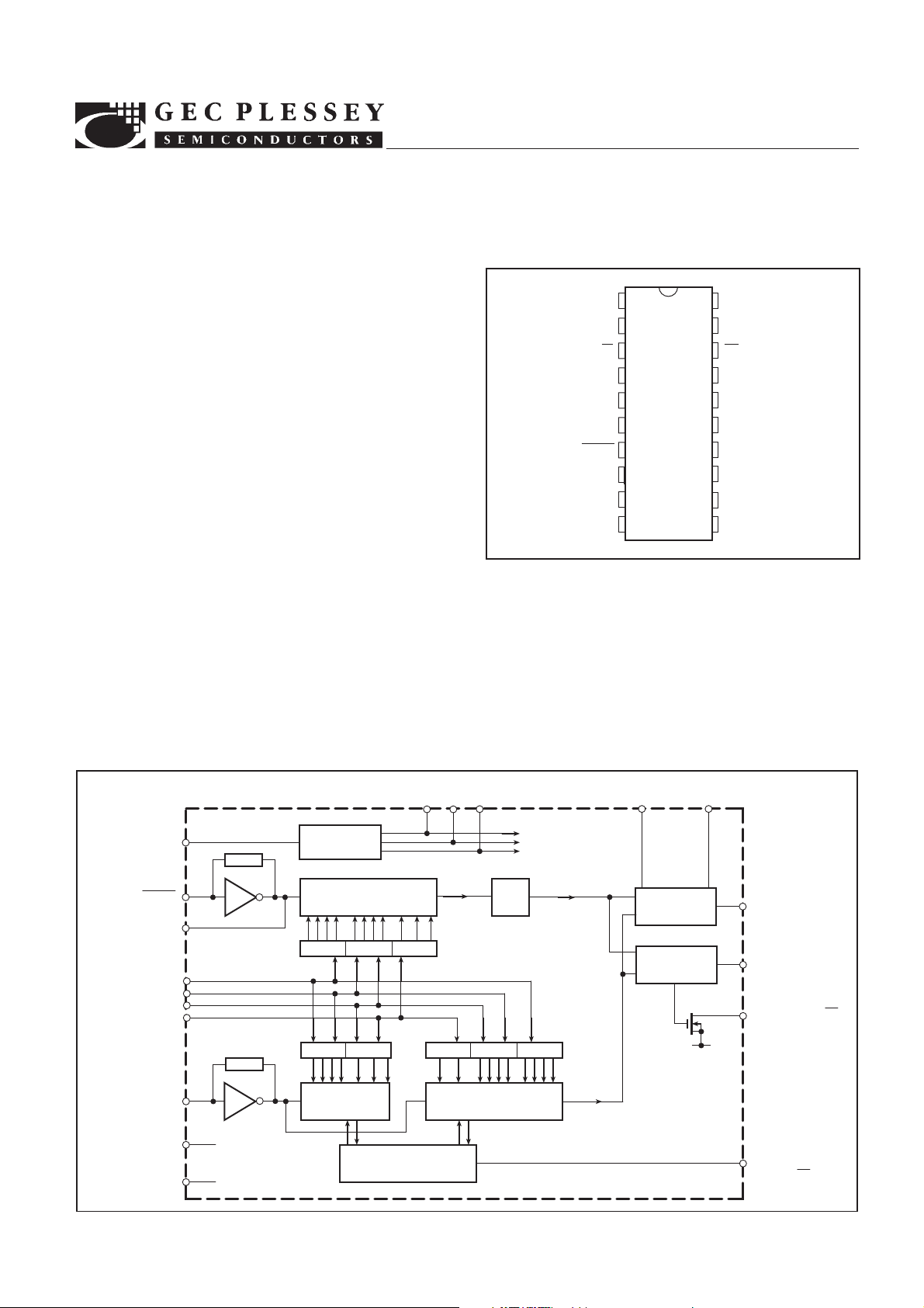
Fig.1 Pin connections - top view
ABSOLUTE MAXIMUM RATINGS
Supply voltage, VDD2V
Input voltage
Open drain output, pin 3
All other pins
Storage temperature
Storage temperature
SS
V
(DG package, NJ8823MA)
(DP and MP packages, NJ8823)
NJ8823
DS3279-1.3
CH
RB
MC
DS2
DS1
DS0
PE
NC
D3
D2
SS
DP20, MP20
DG20
20·5V to 7V
20·3V to VDD10·3V
265°C to 1150°C
255°C to 1125°C
7V
PROGRAM
ENABLE (PE)
OSC IN
OSC OUT
D0
DATA
D1
INPUTS
D2
D3
F
V
DD
V
SS
DATA SELECT INPUTS
DS0 DS1 DS2
15 16 17
14
7
8
9
10
11
12
4
IN
6
5
LATCH SELECT
LOGIC
REFERENCE COUNTER
(11BITS)
LATCH 6 LATCH 7 LATCH 8
LATCH 4 LATCH 5
‘A’ COUNTER
(7 BITS)
CONTROL LOGIC
LATCH 1 LATCH 2 LATCH 3
‘M’ COUNTER
(10 BITS)
42
TO
INTERNAL
LATCHES
f
f
r
v
RB CH
19 20
SAMPLE/HOLD
PHASE
DETECTOR
FREQUENCY/
PHASE
DETECTOR
1
PDA
2
PDB
3
LOCK DETECT (LD)
V
SS
MODULUS
18
CONTROL
OUTPUT (MC)
Fig.2 Block diagram
Page 3
NJ8823
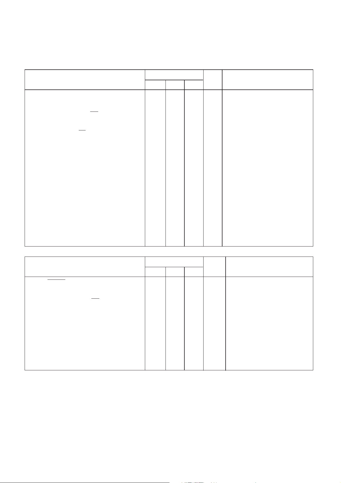
ELECTRICAL CHARACTERISTICS AT VDD = 5V
Test conditions unless otherwise stated:
V
DC Characteristics
=5V ±0·5V. Temperature range NJ8823 BA: –30°C to +70°C; NJ8823 MA: –40°C to +85°C
DD–VSS
Characteristic
Supply current
OUTPUT LEVELS
Modulus Control Output (
MC)
High level
Low level
Lock Detect Output (
LD)
Low level
Open drain pull-up voltage
PDB Output
High level
Low level
3-state leakage current
INPUT LEVELS
Data Inputs (D0-D3)
High level
Low level
Program Enable Input (PE)
High level
Low level
Data Select Inputs (DS0-DS2)
High level
Low level
Min.
4·6
4·6
4·25
4·25
4·25
Value
Typ. Max.
3·5
0·7
5·5
1·5
0·4
0·4
0·4
±0·1
0·4
0·75
0·75
Units
mA
mA
V
V
V
7
V
V
V
, f
f
osc
, f
f
osc
I
SOURCE
I
SINK
I
SINK
I
SOURCE
I
SINK
= 1mA
= 4mA
= 5mA
= 10MHz
FIN
= 1·0MHz
FIN
= 1mA
= 5mA
Conditions
0 to 5V
square
wave
µA
TTL compatible
V
See note 1
V
V
V
V
V
AC Characteristics
200
Value
Typ. Max.
Units
mVRMS
MHz
Conditions
10MHz AC-coupled sinewave
Input squarewave V
to VSS,
DD
Characteristic
and OSC IN input level
F
IN
Max. operating frequency, f
FIN
and f
osc
Min.
10·6
See note 4.
Propagation delay, clock to MC
Strobe pulse width, t
Data set-up time, t
Data hold time, t
W(ST)
DS
DH
Latch address set-up time, t
Latch address hold time, t
HE
SE
2
1
1
1
1
Digital phase detector propagation delay
Gain programming resistor, RB
5
Hold capacitor, CH
Output resistance, PDA
Digital phase detector gain
NOTES
1. Data inputs have internal pull-up resistors to enable them to be driven from TTL outputs.
2. All counters have outputs directly synchronous with their respective clock rising edges.
3. The finite output resistance of the internal voltage follower and ‘on’ resistance of the sample switch driving this pin will add a finite time constant
to the loop. An external 1nF hold capacitor will give a maximum time constant of 5µs, typically.
4. Operation at up to 15MHz is possible with a full logic swing but is not guaranteed.
30
500
0·4
50
1
5
ns
µs
µs
µs
µs
µs
ns
kΩ
nF
kΩ
V/Rad
See note 2.
See Fig. 6
See note 3.
2
Page 4
PIN DESCRIPTIONS
NJ8823
Pin no.
1
2
3
4
5
6
7, 8
9,10, 11, 12
13
14
15, 16, 17
18
19
20
Name
PDA
PDB
LD
F
IN
V
SS
V
DD
OSC IN/
OSC OUT
D0-D3
NC
PE
DS0-DS2
MC
RB
CH
Description
Analog output from the sample and hold phase comparator for use as a ‘fine’ error signal. Output at
(VDD2VSS)/2 when the system is in lock. Voltage increases as fv phase lead increases; voltage
decreases as fr phase lead increases. Output is linear over only a narrow phase window, determined
by gain (programmed by RB).
Three-state output from the phase/frequency detector for use as a ‘coarse’ error signal.
f
. fr or fv leading: positive pulses with respect to the bias point V
v
fv , fr or fr leading: negative pulses with respect to the bias point V
BIAS
BIAS
fv = fr and phase error within PDA window: high impedance.
An open-drain lock detect output at low level when phase error is within PDA window (in lock); high
impedance at all other times.
The input to the main counters, normally driven from a prescaler, which may be AC-coupled or, when
a full logic swing is available, may be DC-coupled.
Negative supply (ground).
Positive supply.
These pins form an on-chip reference oscillator when a series resonant crystal is connected across
them. Capacitors of appropriate value are also required between each end of the crystal and ground
to provide the necessary additional phase shift. An external reference signal may, alternatively, be
applied to
OSC IN. This may be a low-level signal, AC-coupled, or if a full logic swing is available it may
be DC-coupled. The program range of the reference counter is 3 to 2047, with the division ratio being
twice the programmed number.
Data on these inputs is transferred to the internal data latches during the appropriate data read time
slot. D3 is MSB, D0 is LSB.
No connection
This pin is used as a strobe for the data. A logic ‘1’ on this pin transfers data from the D0-D3 pins to
the internal latch addressed by the data select (DS0-DS2) pins . A logic ‘0’ disables the data inputs.
Data select inputs for addressing the internal data latches
Modulus control output for controlling an external dual-modulus prescaler.
of a count cycle and will remain low until the ‘A’ counter completes its cycle.
MC will be low at the beginning
MC then goes high and
remains high until the ‘M’ counter completes its cycle, at which point both ‘A’ and ‘M’ counters are reset.
This gives a total division ratio of MP1A, where P and P11 represent the dual-modulus prescaler
values. The program range of the ‘A’ counter is 0-127 and therefore can control prescalers with a
division ratio up to and including 4128/129. The programming range of the ‘M’ counter is 8-1023
and, for correct operation,
ratio should be
2
P
2P.
M>A
. Where every possible channel is required, the minimum total division
An external sample and hold phase comparator gain programming resistor should be connected
between this pin and VSS.
An external hold capacitor should be connected between this pin and V
SS
.
2·0
VDD = 5V
OSC IN, F
1·5
1·0
SUPPLY CURRENT (mA)
0·5
= 0V TO 5V SQUARE WAVE
IN
1 2 3 4 5 6 7 8 9 10
OSC IN
TOTAL SUPPLY CURRENT IS
THE SUM OF THAT DUE TO
AND OSC IN
INPUT FREQUENCY (MHz)
FIN
FIN
8
7
6
5
4
3
SUPPLY CURRENT (mA)
2
1
0·2 0·4 0·6 0·8 1·0 1·2 1·4 1·6
VDD = 5V
= LOW FREQUENCY
F
IN
0V TO 5V SQUARE WAVE
10MHz
1MHz
INPUT LEVEL (V RMS)
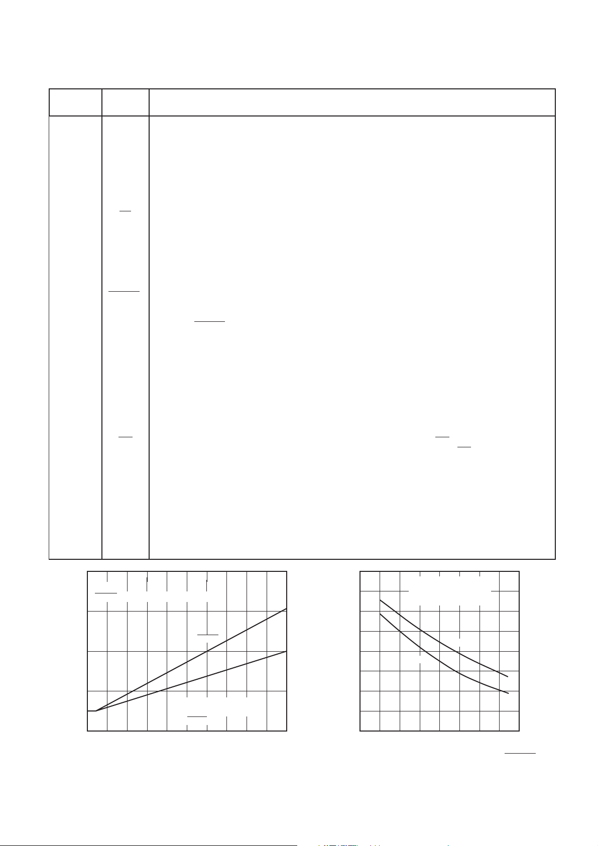
Fig. 3 Typical supply current v. input frequency Fig. 4 Typical supply current v. input level, OSC IN
3
Page 5
NJ8823
PROGRAMMING
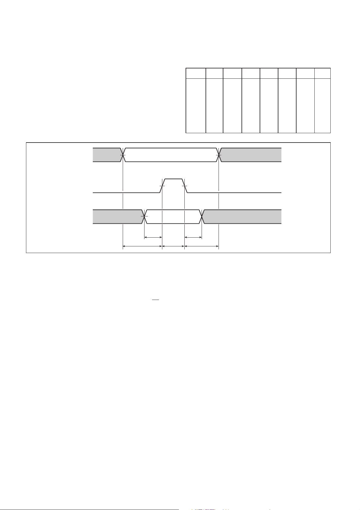
Timing is generated externally, normally from a
microprocessor, and allows the user to change the data in
selected latches as defined by the data map Fig.5. The PE pin
is used as a strobe for the data: taking PE high causes data to
be transferred from the data pins (D0-D3) into the addressed
latch. Following the falling edge of PE, the data is retained in
the addressed latch and the data inputs are disabled. Data
transfer from all internal latches into the counters occurs
simultaneously with the transfer of data into latch 1, which
would therefore normally be the last latch addressed during
each channel change. Timing information for this mode of
operation is given in Fig. 6.
When re-programming,the counters are changed only when
they reach a zero state. There is no reset to zero state, which
means that the synthesiser loop lock-up time will be variable.
DS0-DS2
PE
For the case when only small changes in frequency are
required, the non-resettable synthesiser should achieve the
shortest loop lock-up times.
WORD
1
2
3
4
5
6
7
8
DS2
0
0
0
0
1
1
1
1
DS1
0
0
1
1
0
0
1
1
DS0
D3
D2
D1
D0
M1
0
1
0
1
0
1
0
1
M5
M9
A3
R3
R7
-
M0
M4
M8
A2
A6
R2
R6
R10
M3
M7
A1
A5
R1
R5
R9
-
M2
M6
A0
A4
R0
R4
R8
Fig. 5 Data map
D0 - D3
t
DS
t
SE
Fig. 6 Timing diagram
PHASE COMPARATORS
The digital phase/frequency detector drives a three-state
output, PDB, which provides a ‘coarse’ error signal to enable
fast switching between channels. The PDB output is active
until the phase error is within the sample and hold phase
detector, PDA, window, when PDB becomes high impedance.
Phase-lock is indicated at this point by a low level on
sample and hold phase detector provides a ‘fine’ error signal
to give further phase adjustment and to hold the loop in lock.
An internally generated ramp, controlled by the digital
output from both the reference and main divider chains, is
sampled at the reference frequency to give the ‘fine’ error
signal, PDA. When in phase lock, this output would be typically
at (V
DD2VSS
)/2 and any offset from this would be proportional
to phase error. The relationship between this offset and the
LD. The
t
DH
t
W(ST)
t
HE
phase error is the phase comparator gain, which is
programmable with an external resistor, RB. An internal 50pF
capacitor is used in the sample and hold comparator.
CRYSTAL OSCILLATOR
When using the internal oscillator, the stability may be
enhanced at high frequencies by the inclusion of a resistor
between pin 8 (OSC OUT) and the other components. A value
of 150-270Ω is advised.
PROGRAMMING/POWER UP
Data and signal input pins should not have input applied to
them prior to the application of V
occur.
, as otherwise latch-up may
DD
4
Page 6

NJ8823
HEADQUARTERS OPERATIONS
GEC PLESSEY SEMICONDUCTORS
Cheney Manor, Swindon,
Wiltshire SN2 2QW, United Kingdom.
Tel: (0793) 518000
Fax: (0793) 518411
CUSTOMER SERVICE CENTRES
• FRANCE & BENELUX Les Ulis Cedex Tel: (1) 64 46 23 45 Fax : (1) 64 46 06 07
• GERMANY Munich Tel: (089) 3609 06-0 Fax : (089) 3609 06-55
• ITALY Milan Tel: (02) 66040867 Fax: (02) 66040993
• JAPAN Tokyo Tel: (03) 5276-5501 Fax: (03) 5276-5510
• NORTH AMERICA Scotts Valley, USA Tel (408) 438 2900 Fax: (408) 438 7023.
• SOUTH EAST ASIA Singapore Tel: (65) 3827708 Fax: (65) 3828872
GEC PLESSEY SEMICONDUCTORS
P.O. Box 660017
1500 Green Hills Road,
Scotts Valley, California 95067-0017,
United States of America.
• SWEDEN Stockholm, Tel: 46 8 702 97 70 Fax: 46 8 640 47 36
• TAIWAN, ROC Taipei Tel: 886 2 5461260. Fax: 886 2 71900260
• UK, EIRE, DENMARK, FINLAND & NORWAY
Swindon Tel: (0793) 518510 Fax : (0793) 518582
These are supported by Agents and Distributors in major countries world-wide.
Tel: (408) 438 2900
Fax: (408) 438 5576
This publication is issued to provide information only which (unless agreed by the Company in writing) may not be used, applied or reproduced for any purpose nor form part of any order or contract nor to be regarded
as a representation relating to the products or services concerned. No warranty or guarantee express or implied is made regarding the capability, performance or suitability of any product or service. The Company
reserves the right to alter without prior knowledge the specification, design or price of any product or service. Information concerning possible methods of use is provided as a guide only and does not constitute
any guarantee that such methods of use will be satisfactory in a specific piece of equipment. It is the user's responsibility to fully determine the performance and suitability of any equipment using such information
and to ensure that any publication or data used is up to date and has not been superseded. These products are not suitable for use in any medical products whose failure to perform may result in significant injury
or death to the user. All products and materials are sold and services provided subject to the Company's conditions of sale, which are available on request.
GEC Plessey Semiconductors 1992
Page 7

For more information about all Zarlink products
visit our Web Site at
www.zarlink.com
Information relating to products and services furnished herein by Zarlink Semiconductor Inc. trading as Zarlink Semiconductor or its subsidiaries (collectively
is believed to be reliable. However, Zarlink assumes no liability for errors that may appear in this publication, or for liability otherwise arising from the application or
use of any such information, product or service or for any infringement of patents or other intellectual property rights owned by third parties which may result from
such application or use. Neither the supply of such information or purchase of product or service conveys any license, either express or implied, under patents or
other intellectual property rights owned by Zarlink or licensed from third parties by Zarlink, whatsoever. Purchasers of products are also hereby notified that the use
of product in certain ways or in combination with Zarlink, or non-Zarlink furnished goods or services may infringe patents or other intellectual property rights owned
by Zarlink.
This publication is issued to provide information only and (unless agreed by Zarlink in writing) may not be used, applied or reproduced for any purpose nor form part
of any order or contract nor to be regarded as a representation relating to the products or services concerned. The products, their specifications, services and other
information appearing in this publication are subject to change by Zarlink without notice. No warranty or guarantee express or implied is made regarding the capability,
performance or suitability of any product or service. Information concerning possible methods of use is provided as a guide only and does not constitute any guarantee
that such methods of use will be satisfactory in a specific piece of equipment. It is the user
equipment using such information and to ensure that any publication or data used is up to date and has not been superseded. Manufacturing does not necessarily
include testing of all functions or parameters. These products are not suitable for use in any medical products whose failure to perform may result in significant injury
or death to the user. All products and materials are sold and services provided subject to Zarlink
Purchase of Zarlink s I
that the system conforms to the I
2
C components conveys a licence under the Philips I
2
C Standard Specification as defined by Philips.
’
s responsibility to fully determine the performance and suitability of any
’
s conditions of sale which are available on request.
2
C Patent rights to use these components in and I
2
C System, provided
“
Zarlink
Zarlink and the Zarlink Semiconductor logo are trademarks of Zarlink Semiconductor Inc.
Copyright 2001, Zarlink Semiconductor Inc. All Rights Reserved.
”
)
TECHNICAL DOCUMENTATION - NOT FOR RESALE
 Loading...