

Page 1
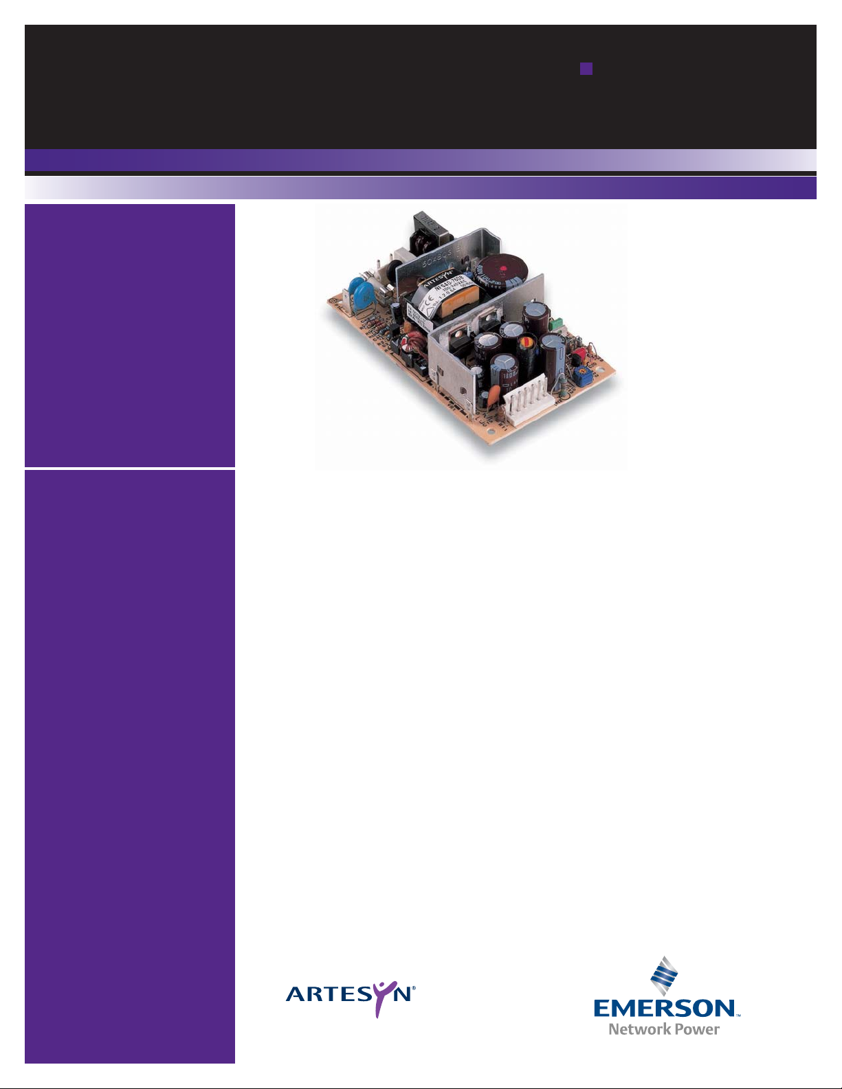
The NFS40 series is a 40 W universal input ac-dc power supply on a
5" x 3" card with a maximum component height of 1.2" for use in
1U applications. The NFS40 series is available with a wide range of
models in the industry standard 5" x 3" footprint and has proven
itself to be highly reliable and versatile product for a wide range of
communication and industrial applications. The NFS40 provides
40 W of output power with free air convection cooling which can
be boosted to 50 W with 20 CFM of air. Standard features include
OVP and short-circuit protection. The series, with full international
safety approval and the CE mark, meets conducted noise
EN55022 level A. The NFS40 series is designed for use in low
power data networking, computer, telecom and industrial
applications such as hubs, routers, POS terminals, cable modems,
PABX's, industrial PC's and machine control.
Embedded Power for
Business-Critical Continuity
NFS40 Series
SIngle and
triple output
Special Features
• 5.0 x 3.0 x 1.2 inch package
(1U applications)
• Industry standard package
• Overvoltage and
short circuit protection
• 40 W with free air convection
• EN55022, EN55011
conducted noise level A
• UL, VDE and CSA
safety approvals
• Available RoHS compliant
• 2 year warranty
Total Power: 40 - 50W
Input Voltage: 85 - 264VAC
120 - 370VDC
# of Outputs: Single, triple
Safety
VDE0805/EN60950/
IEC950/IEC1010
File No. 10401-3336-0044
Licence No. 2559
UL1950 File No. E136005
CSA C22.2 No. 950
File No. LR41062C
Rev.02.16.07
NFS40 Series
1 of 4
Page 2
Rev.02.16.07
NFS40 Series
2 of 4
Embedded Power for
Business-Critical Continuity
All specifications are typical at nominal input, full load at 25°C unless otherwise stated
Specifications
GENERAL SPECIFICATIONS
Hold-up time 110 Vac, 40 Watts 14 ms
230 Vac, 40 Watts 110 ms
Efficiency 70% typical
Isolation voltage Input/output 3000 Vac
Input/chassis 1500 Vac
Switching frequency Variable
Approvals and VDE0805, EN60950
standards IEC950, IEC1010, UL1950
(See Note 13) CSA C22.2 No. 950
Weight 280 g (9.88 oz)
MTBF (See Note 9) MIL-HDBK-217E 170,000 hours
ENVIRONMENTAL SPECIFICATIONS
Thermal performance Operating 0 °C to +70 °C
(See Notes 8, 10) Non-operating -40 °C to +85 °C
50 ¡C ambient temp., 40 W
Convection cooled
Forced air cooling 50 W @ 20 CFM
50 ¡C to 70 ¡C ambient Derate linearly
to 50% load
Peak (60 seconds) 60 W
Relative humidity Non-condensing 5% to 80% RH
Altitude Operating 10,000 feet max.
Non-operating 40,000 feet max.
Vibration (See Note 11) 5 Hz to 500 Hz 2.4 G rms peak
OUTPUT SPECIFICATIONS
Output voltage +5 V output on triples ±5.0%
adjustability Vout on singles ±5.0%
Line regulation Main output ±0.2%
LL to HL, FL Auxiliary outputs ±1.0%
Load regulation Main output ±2.0%
FL to NL Auxiliary outputs ±5.0%
Transient response +5 V (1.5-3 A) ±120 mV max. dev.
500 μs recovery
Temperature coefficient All outputs ±0.02%/°C
Overvoltage protection +5 V output 125% ±15% Vout
Output power limit Primary power limited 90 W input
power limit
Short circuit protection Single outputs Continuous
Multiple outputs Short term
INPUT SPECIFICATIONS
Input voltage range Universal input 85-264 Vac
120-370 Vdc
Input frequency range 47-440Hz
Max. input surge 132 Vac, cold start 12 A max.
current 264 Vac, cold start 24 A max.
Safety ground 110 Vac, 60 Hz 0.13 mA max.
leakage current 230 Vac, 50 Hz 0.32 mA max.
EMC CHARACTERISTICS
Conducted emissions EN55022, FCC part 15 Level A
Radiated emissions EN55022 Level A
ESD air EN61000-4-2, level 3 Perf. criteria 1
ESD contact EN61000-4-2, level 4 Perf. criteria 1
Surge EN61000-4-5, level 3 Perf. criteria 1
Fast transients EN61000-4-4, level 3 Perf. criteria 1
Radiated immunity EN61000-4-3, level 3 Perf. criteria 2
Conducted immunity EN61000-4-6, level 3 Perf. criteria 2
Page 3

Rev.02.16.07
NFS40 Series
3 of 4
Embedded Power for
Business-Critical Continuity
Specifications Contd.
Notes
1 Natural convection cooled, 40 W maximum.
2 Peak output current lasting less than 30 seconds with duty cycle less than 10%.
During peak loading, outputs may go outside of total regulation limits. Peak
total power must not exceed 60 W.
3 Forced air, 20 CFM at 1 atmosphere, 50 W maximum.
4 Figure is peak-to-peak. Output noise is measured across a 50 MHz bandwidth
using a 12 inch twisted pair, terminated with a 47 μF capacitor.
5 Total regulation is defined as the static output regulation at 25
°C, including
initial tolerance, line voltage within stated limits, load currents within stated
limits, and output voltages adjusted to their factory settings. Also,
0.25<I(A)/I(B)<5.0 to maintain stated regulation. This does not apply to the
NFS40-7628 power supply as it has regulated auxiliary outputs.
6 A minimum load of 0.5 A is required on the +5 V output to obtain full current
from the negative output.
7 The NFS40 offers the possibility of power sharing between outputs. Consult
factory for details.
8 Derating curve is application specific for ambient temperatures >50
°C, for
optimum reliability no part of the heatsink should exceed 110
o
C and no
semiconductor case temperature should exceed 115
o
C.
9 A 4 W minimum load is recommended to achieve the design MTBF.
10 Caution: Allow a minimum of 1 second after disconnecting the power when
making thermal measurements.
11 Three orthogonal axes, sweep at 1 octave/minute, 5 minute dwell at four major
resonances.
12 The NFS40-7628 has separately linear regulated +12 V and -12 V outputs. The
loading conditions in Notes 5 and 6 do not apply.
13 This product is only for inclusion by professional installers within other
equipment and must not be operated as a stand alone product.
14 The ‘J’ suffix indicates that these parts are Pb-free (RoHS 6/6) compliant. TSE
RoHS 5/6 (non Pb-free) compliant versions may be available on special request,
please contact your local sales representative for details.
15 NOTICE: Some models do not support all options. Please contact your local
Artesyn representative or use the on-line model number search tool at
http://www.artesyn.com/powergroup/products.htm to find a suitable
alternative.
OUTPUT
OUTPUT CURRENTS
RIPPLE
(4)
TOTAL
MODEL NUMBER
(14,15,D)
VOLTAGE
MAX
(1)
PEAK
(2)
FAN
(3)
REGULATION
(5)
+5.1 V (A) 3 A 7 A 5 A 50 mV ±2.0% NFS40-7608J
(5,6)
+12.0 V (B) 2 A 3 A 2 A 120 mV ±5.0%
-12.0 V (C) 0.35 A 1 A 0.5 A 120 mV ±5.0%
+5.1 V (A) 4 A 7 A 5 A 50 mV ±2.0% NFS40-7628J
(12)
+12.0 V (B) 0.35 A 1 A 0.5 A 120 mV ±5.0%
-12.0 V (C) 0.35 A 1 A 0.5 A 120 mV ±5.0%
+5.1 V (A) 3 A 7 A 5 A 50 mV ±2.0% NFS40-7607J
(5,6)
+12.0 V (B) 2 A 3 A 2 A 120 mV ±5.0%
-5.0 V (C) 0.35 A 1 A 0.5 A 50 mV ±5.0%
+5.1 V (A) 3 A 7 A 5 A 50 mV ±2.0% NFS40-7610J
(5,6)
+15.0 V (B) 2 A 2.5 A 2 A 150 mV +10%/-3.0%
-15.0 V (C) 0.35 A 1 A 0.5 A 150 mV ±5.0%
+5.1 V 6 A 12 A 8 A 100 mV ±2.0% NFS40-7605J
+12.0 V 3.3 A 5 A 4 A 120 mV ±2.0% NFS40-7612J
+15.0 V 2.6 A 4 A 3.3 A 150 mV ±2.0% NFS40-7615J
+24.0 V 1.6 A 2.5 A 2 A 240 mV ±2.0% NFS40-7624J
PIN CONNECTIONS
J1 -7608J, -7628J -7607J -7610J SINGLES
Pin 1 AC Live AC Live AC Live AC Line
Pin 2 AC Neutral AC Neutral AC Neutral AC Neutral
J2
Pin 1 +12 V +12 V +15 V +Vout
Pin 2 +5.1 V +5.1 V +5.1 V +Vout
Pin 3 +5.1 V +5.1 V +5.1 V +Vout
Pin 4 Return Return Return Return
Pin 5 Return Return Return Return
Pin 6 -12 V -5 V -15 V Return
P1
(C)
Pin 1 Safety Ground
DERATING CURVE (See Notes 8, 9, 10)
Output Power (Watts)
50W
20 CFM FORCED AIR COOLING
40W
4W MIN. LOAD REQUIRED TO ACHIEVE DESIGN MTBF
4W
0°C 10°C 20°C 30°C 40°C 50°C 60°C 70°C
NATURAL
CONVECTION
COOLING
25W
20W
Page 4

Embedded Power for
Business-Critical Continuity
Rev.02.16.07
NFS40 Series
4 of 4
Emerson Network Power and the Emerson
Network Power logo are trademarks and
service marks of Emerson Electric Co.
©2007 Emerson Electric Co.
Emerson Network Power.
The global leader in enabling
business-critical continuity.
EmersonNetworkPower. com
AC Power
Connectivity
DC Power
Embedded Power
Inbound Power
Integrated Cabinet Solutions
Outside Plant
Precision Cooling
Site Monitoring and Services
Americas
5810 Van Allen Way
Carlsbad, CA 92008
USA
Telephone: +1 760 930 4600
Facsimile: +1 760 930 0698
Europe (UK)
Waterfront Business Park
Merry Hill, Dudley
West Midlands, DY5 1LX
United Kingdom
Telephone: +44 (0) 1384 842 211
Facsimile: +44 (0) 1384 843 355
Asia (HK)
16th - 17th Floors, Lu Plaza
2 Wing Yip Street, Kwun Tong
Kowloon, Hong Kong
Telephone: +852 2176 3333
Facsimile: +852 2176 3888
For global contact, visit:
www.powerconversion.com
technicalsupport@powerconversion.com
While every precaution has been taken to ensure
accuracy and completeness in this literature, Emerson
Network Power assumes no responsibility, and disclaims
all liability for damages resulting from use of this
information or for any errors or omissions.
Mechanical Notes
A In order to meet safety requirements, a non-metallic stand-off is mandatory for one hole as specified in the mechanical
drawing above.
B The ground pad of the mounting hole near P1 allows system grounding through a metal stand-off.
C To improve conducted noise, the ground pad of the mounting hole near the output connector should be connected with
the ground pad of the mounting hole near P1. Use metal stand-offs attached to a common metal chassis. This connection
also significantly attenuates common mode noise.
D A standard L-bracket and cover is available for mounting which contains all screws, connectors and necessary mounting
hardware. Order part number ‘NFS40 COVER KIT’.
5.00
0.156 (3.96) Dia.
(4 Places)
(127.00)
3.00
(76.2)
0.22
(5.59)
NON-METALLIC
STAND-OFF
(SEE NOTE A)
J1
~
N
~
L
F1
F 3.15A, H 250VAC
P1 (SEE NOTE C)
C5
Q1
T1
4.55
(115.8)
ALL DIMENSIONS IN INCHES (mm)
MAXIMUM
COMPONENT
HEIGHT 1.2
inches
J2
1
2.550
(64.8)
0.22 (5.59)
 Loading...