

Page 1

INTEGRATED CIRCUITS
NE/SA576
Low power compandor
Product specification 1993 Dec 15
IC17 Data Handbook
Page 2
Philips Semiconductors Product specification
SYMBOL
PARAMETER
UNITS
NE/SA576Low power compandor
DESCRIPTION
The NE/SA576 is a unity gain level programmable compandor
designed for low power applications. The NE576 is internally
configured as an expandor and a compressor to minimize external
component count.
The NE576 can operate at 1.8V . During normal operations, the
NE576 can operate from at least a 2V battery. If the battery voltage
drops to 1.8V , this part will still continue to function, however, turning
on the part at a V
V
to half VCC. One resistor connects between VCC and V
REF
the other connects from V
of 1.8V requires two external resistors to bring
CC
to ground. A typical value for these
REF
REF
;
external resistors is approximately 20k. A lower value can be used,
but the power consumption will go up.
The NE576 is available in a 14-pin plastic DIP and SO packages.
FEATURES
•Operating voltage range: 1.8V to 7V
•Low power consumption
(1.4mA @ 3.6V)
•Over 80dB of dynamic range
•Wide input/output swing capability
(rail-to-rail)
•Low external component count
•ESD hardened
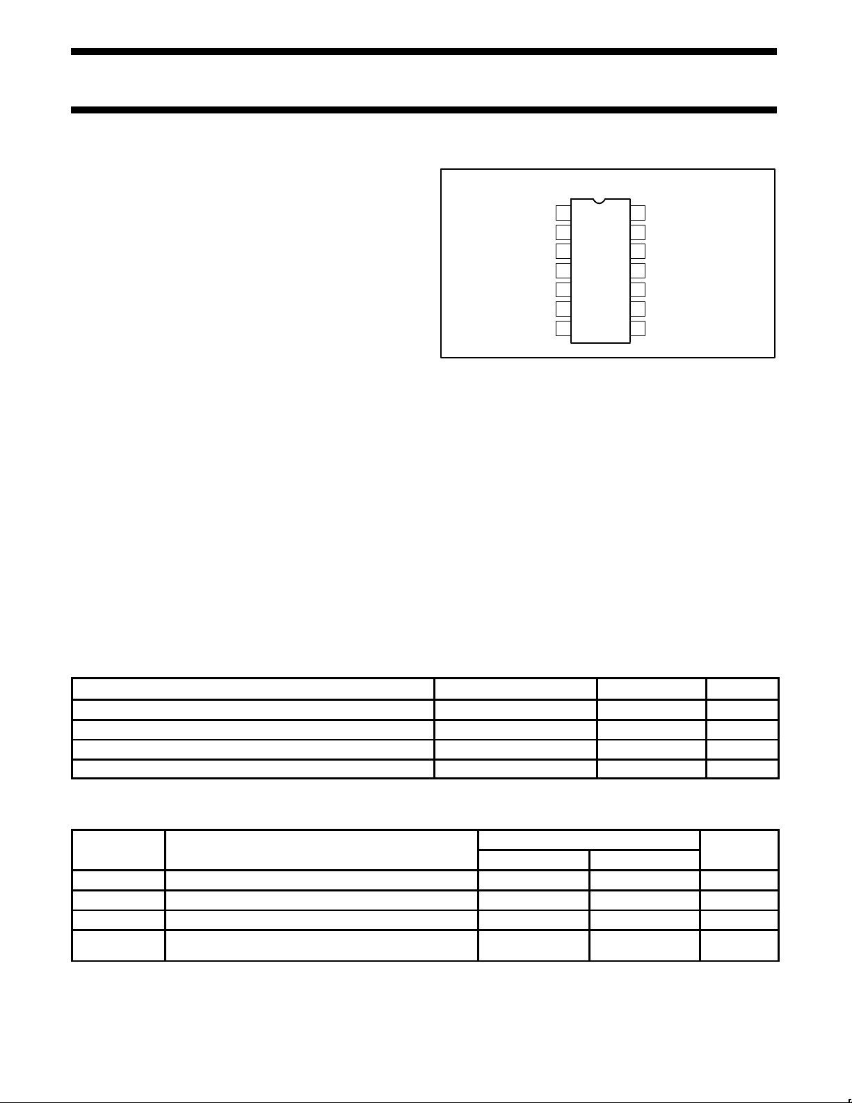
PIN CONFIGURATION
D and N Packages
OUT
V
I
REF
GND
IN
IN
CAP
REF
1
2
3
4
5
6
7
GCELL
RECT
EXP
EXP
Figure 1. Pin Configuration
APPLICATIONS
•Cordless telephone
•Consumer audio
•Wireless microphones
•Modems
•Electric organs
•Hearing aids
•Automatic level control
14
V
CC
13
COMP
CAP2
12
COMP
IN
11
COMP
CAP1
10
RECT
IN
9
GCELL
IN
8
COMP
OUT
SR00713
ORDERING INFORMATION
DESCRIPTION TEMPERATURE RANGE ORDER CODE DWG #
14-Pin Plastic Dual In-Line Package (DIP) 0 to +70°C NE576N SOT27-1
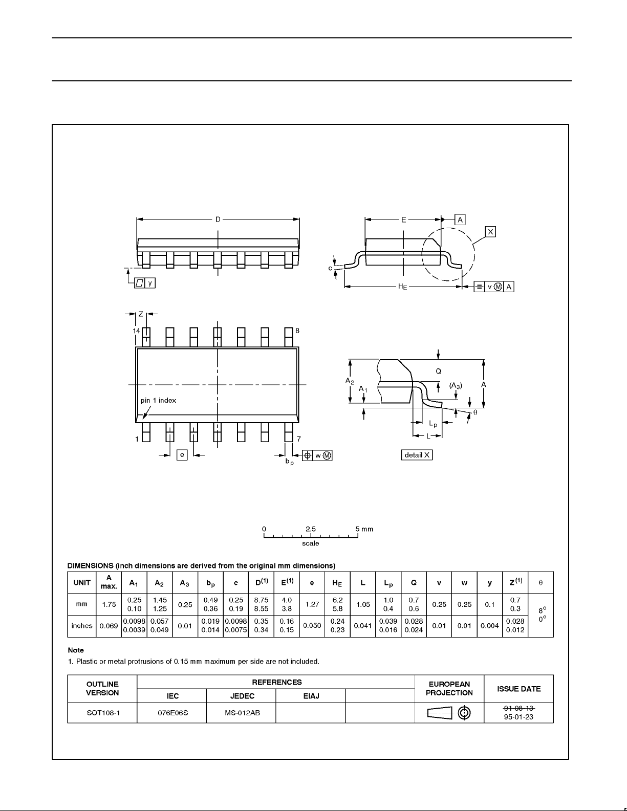
14-Pin Plastic Small Outline (SO) 0 to +70°C NE576D SOT108-1
14-Pin Plastic Dual In-Line Package (DIP) –40 to +85°C SA576N SOT27-1
14-Pin Plastic Small Outline (SO) –40 to +85°C SA576D SOT108-1
ABSOLUTE MAXIMUM RATINGS
RATING
NE576 SA576
T
V
θ
CC
T
A
STG
JA
Supply voltage 8 8 V
Operating ambient temperature range 0 to +70 –40 to +85 °C
Storage temperature range –65 to +150 –65 to +150 °C
Thermal impedance DIP
SO
90
125
90
125
°C/W
°C/W
1993 Dec 15 853-1536 11649
2
Page 3
Philips Semiconductors Product specification
V
V
NE/SA576Low power compandor
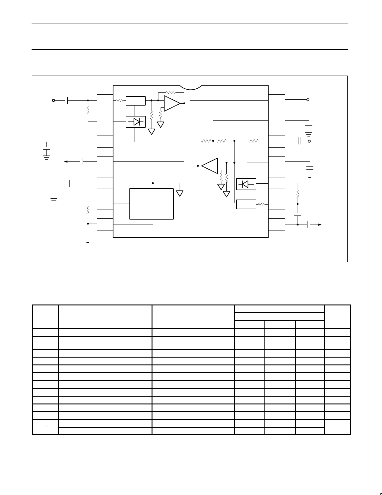
BLOCK DIAGRAM and TEST AND APPLICATION CIRCUIT
C1
EXP
IN
+
10µF
RECT
EXP
CAP
+
2.2µF
C2
C3
EXP
OUT
10µF
C4
V
REF
*R1, R2 and R3 are 1% resistors.
+
10µF
R2*
V
REF
GND
10k
C7
10µF
CAP2
+
CAP1
RECT
R3*
GCELL
+
C5
+
V
C8
COMP
+
IN
C9
10µF
CC
2.2µF
C6
2.2µF
IN
IN
COMP
SR00714
OUT
Σ
5k
14
COMP
13
30k 30k 10k
Σ
10k
8.6k
RECTIFIER
12
11
+
COMP
10
10k
V
CC
COMPRESSOR
∆G
GAINCELL
9
10µF
8
GAINCELL
10k
1
R1*
IN
RECTIFIER
2
∆G
10k
3
+
4
EXPANDOR
5
6
I
REF
BANDGAP
7
GND
Figure 2. Block Diagram and Test and Application Circuit
ELECTRICAL CHARACTERISTICS
TA = 25°C, VCC = 3.6VDC, compandor 0dB level = –20dBV = 100mV
R1, R2 and R3 are 1% resistors.
SYMBOL PARAMETER TEST CONDITIONS NE/SA576 UNITS
1
2
V
V
I
Supply voltage
CC
Supply current
CC
Reference voltage
REF
R
Summing amp output load 10 kΩ
L
THD Total harmonic distortion 1kHz, 0dB, BW = 3.5kHz 0.25 1.5 %
E
Expandor output noise voltage BW = 20kHz, RS = 0Ω 10 30 µV
NO
0dB Unity gain level 0dB at 1kHz –1.5 0.18 1.5 dB
V
Output voltage offset No signal –150 1 150 mV
OS
Expandor output DC shift No signal to 0dB –100 7 100 mV
Tracking error relative to 0dB output -20dB expandor –1.0 0.3 1.0 dB
Crosstalk, COMP to EXP 1kHz, 0dB, C
Output swing low 0.2
O
Output swing high VCC – 0.2
NOTE:
1. Operation down to V
2. Reference voltage, V
= 1.8V is possible, see description on front page of NE576 data sheet.
CC
, is typically at 1/2 VCC.
REF
, output load RL = 10kΩ, Freq = 1kHz, unless otherwise specified.
RMS
LIMITS
MIN TYP MAX
2 3.6 7 V
No signal
= 100kΩ
R
2
1.4 3 mA
VCC = 3.6V 1.8 V
= 10µF –80 dB
REF
1993 Dec 15
3
Page 4
Philips Semiconductors Product specification
NE/SA576Low power compandor
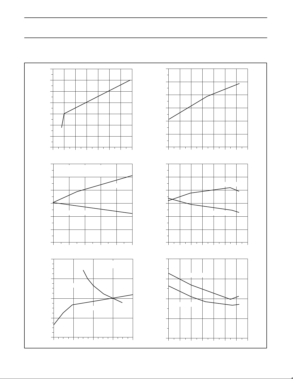
TYPICAL PERFORMANCE CHARACTERISTICS
VCC = 3.6V, TA = 25°C, R1=R3=7.15kΩ, R2=100kΩ, 0dB level = 100mV, Freq. = 1kHz
SUPPLY CURRENT vs SUPPLY VOLTAGE
SUPPLY CURRENT vs TEMPERATURE
1.6
1.8
1.6
1.4
1.2
1
SUPPLY CURRENT (mA)
0.8
0.6
12345678
UNITY GAIN ERROR vs SUPPLY VOLTAGE
0.6
NOTE: UNITY GAIN ERROR MAY BE
SET TO 0 AT ANY V
ADJUSTING THE VALUE OF R1, R3
0.4
0.2
0
-0.2
SUPPLY VOLTAGE (V)
BY
CC
COMPRESSOR
EXPANDOR
1.5
1.4
1.3
1.2
SUPPLY CURRENT (mA)
1.1
1
-40 -20 0 20 40 60 80 100
UNITY GAIN ERROR vs TEMPERATURE
0.6
0.4
0.2
0
-0.2
AMBIENT TEMPERATURE (°C)
EXPANDOR
COMPRESSOR
UNITY GAIN ERROR (dB)
-0.4
-0.6
234567
TRACKING ERROR vs INPUT LEVEL
1
0.5
0
OUTPUT ERROR (dB)
-0.5
-1
23456
SUPPLY VOLTAGE (V)
EXPANDOR
COMPRESSOR
INPUT LEVEL (dB)
NOTE: RELATIVE
TO UNITY GAIN
Figure 3. Typical Performance Characteristics
UNITY GAIN ERROR (dB)
-0.4
-0.6
-40 -20 0 20 40 60 80 100
0.5
0.4
0.3
THD (%)
0.2
0.1
-40 -20 0 20 40 60 80 100
TEMPERATURE (°C)
THD vs TEMPERATURE
COMPRESSOR
EXPANDOR
TEMPERATURE (°C)
SR00715
1993 Dec 15
4
Page 5
Philips Semiconductors Product specification
NE/SA576Low power compandor
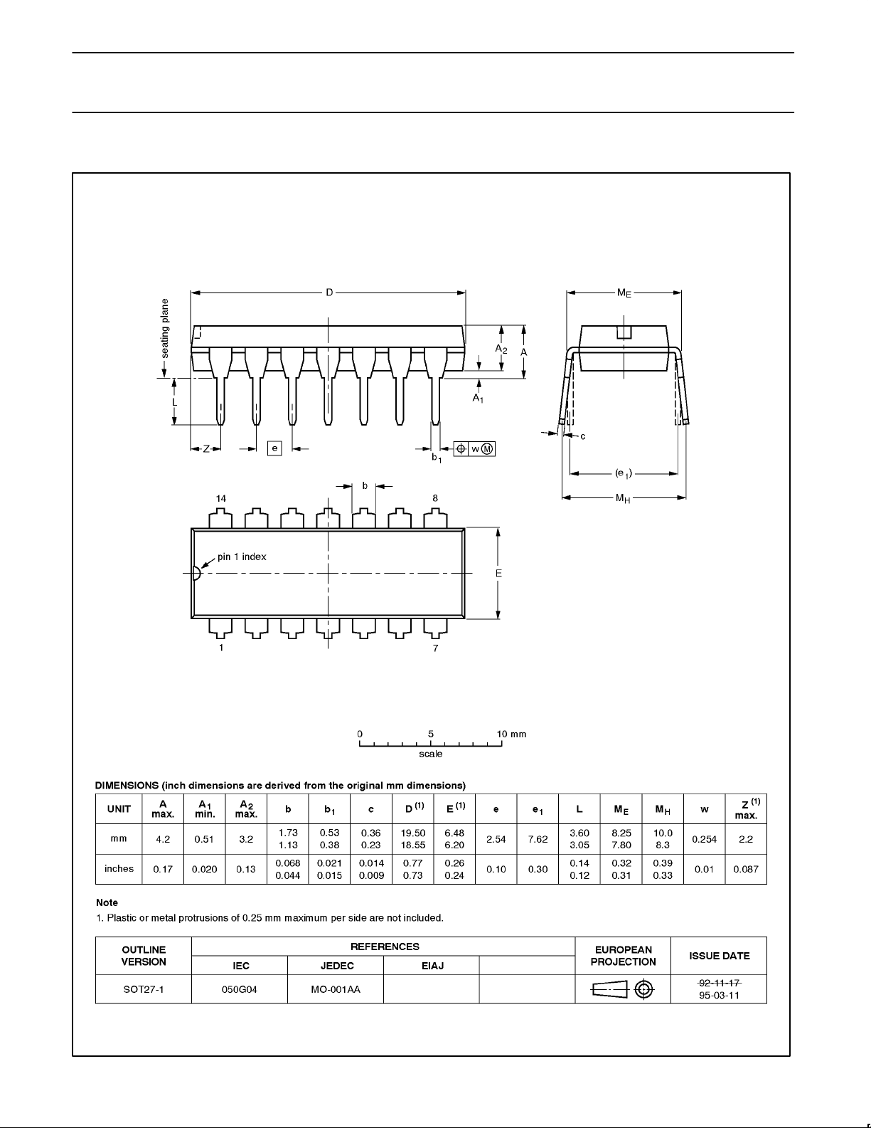
DIP14: plastic dual in-line package; 14 leads (300 mil) SOT27-1
1993 Dec 15
5
Page 6
Philips Semiconductors Product specification
NE/SA576Low power compandor
SO14: plastic small outline package; 14 leads; body width 3.9 mm SOT108-1
1993 Dec 15
6
Page 7

Philips Semiconductors Product specification
NE/SA576Low power compandor
DEFINITIONS
Data Sheet Identification Product Status Definition
Objective Specification
Preliminary Specification
Product Specification
Formative or in Design
Preproduction Product
Full Production
This data sheet contains the design target or goal specifications for product development. Specifications
may change in any manner without notice.
This data sheet contains preliminary data, and supplementary data will be published at a later date. Philips
Semiconductors reserves the right to make changes at any time without notice in order to improve design
and supply the best possible product.
This data sheet contains Final Specifications. Philips Semiconductors reserves the right to make changes
at any time without notice, in order to improve design and supply the best possible product.
Philips Semiconductors and Philips Electronics North America Corporation reserve the right to make changes, without notice, in the products,
including circuits, standard cells, and/or software, described or contained herein in order to improve design and/or performance. Philips
Semiconductors assumes no responsibility or liability for the use of any of these products, conveys no license or title under any patent, copyright,
or mask work right to these products, and makes no representations or warranties that these products are free from patent, copyright, or mask
work right infringement, unless otherwise specified. Applications that are described herein for any of these products are for illustrative purposes
only. Philips Semiconductors makes no representation or warranty that such applications will be suitable for the specified use without further testing
or modification.
LIFE SUPPORT APPLICA TIONS
Philips Semiconductors and Philips Electronics North America Corporation Products are not designed for use in life support appliances, devices,
or systems where malfunction of a Philips Semiconductors and Philips Electronics North America Corporation Product can reasonably be expected
to result in a personal injury. Philips Semiconductors and Philips Electronics North America Corporation customers using or selling Philips
Semiconductors and Philips Electronics North America Corporation Products for use in such applications do so at their own risk and agree to fully
indemnify Philips Semiconductors and Philips Electronics North America Corporation for any damages resulting from such improper use or sale.
Philips Semiconductors
811 East Arques Avenue
P.O. Box 3409
Sunnyvale, California 94088–3409
Philips Semiconductors and Philips Electronics North America Corporation
register eligible circuits under the Semiconductor Chip Protection Act.
Copyright Philips Electronics North America Corporation 1996
All rights reserved. Printed in U.S.A.
Telephone 800-234-7381
print code Date of release: 05-96
Document order number:
 Loading...