

Page 1

DATA SHEET
PHOTO DIODE
NDL5481P Series
1 300 nm OPTICAL ANALOG CATV SYSTEM
φφφφ
µµµµ
80
m InGaAs PIN PHOTO DIODE MODULE WITH SMF
DESCRIPTION
NDL5481P Series is InGaAs PIN photo diode modules with singlemode fiber. They are designed for analog
transmission systems like CATV applications, and feature low intermodulation distortion and 40 dB minimum of
optical return loss.
FEATURES
•
Low intermodulation distortion IMD2 = −75 dBc MAX.
IMD3 = −90 dBc MAX.
•
Optical return loss 45 dB
•
High quantum efficiency
•
Small dark current ID = 0.1 nA
η
= 81 % @ λ = 1 300 nm•Coaxial module with singlemode fiber (SM-9/125)
•
Small capacitance Ct = 0.7 pF
•
Low operating voltage VR = 10 V
•
Detecting area size
•
NDL5481P1 and NDL5481P2 have a flange.
φ
80 µm
NDL5481P
Optical Fiber:
SM-9/125
Length: 1 m MIN.
+0.0
φ
6.0
–0.1
6.9±0.3
–0.1
+0.0
6.0
231
Shrunk tube
φ
2.5
φ
0.45
φ
2.0
30.0 MAX.
12.5 MIN.
3.0±0.3
PACKAGE DIMENSIONS
in millimeters
NDL5481P1
Optical Fiber:
SM-9/125
Length: 1 m MIN.
φ
14.0±0.1
φ
3.9±0.5
6.9±0.3
φ
2– 2.2
1.5
7.0±0.3
231
18.0±0.1
LEAD CONNECTION
1 Anode (Negative)
2 Cathode (Positive)
3 Case
Optical Fiber:
NDL5481P2
SM-9/125
Length: 1 m MIN.
Shrunk tube Shrunk tube
2.5
6.0
+0.0
–0.1
30.0 MAX.
+0.0
φ
6.0
–0.1
4.0±0.1
12.5 MIN.
3
12
4.0±0.3
φ
2.0
0.5±0.1
2.5±0.1
φ
231
12.0±0.1
16.0±0.2
φ
2.5
2– 2.5
2.0
30.0 MAX.
12.5 MIN.
φ
7.0±0.15
•
The information in this document is subject to change without notice.
Document No. P10311EJ3V0DS00 (3rd edition)
Date Published March 1996 P
Printed in Japan
The mark
••••
shows major revised points.
1994©
Page 2
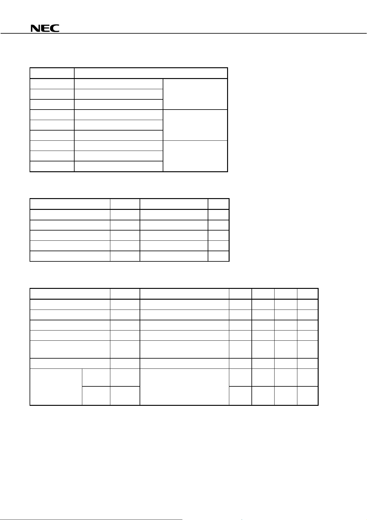
ORDERING INFORMATION
•
Part Number Available Connector
NDL5481P Without Connector no flange
NDL5481PC With FC-UPC Connector
NDL5481PD With SC-UP C Connector
NDL5481P1 Without Connector flat mount flange
NDL5481P1C With FC-UPC Connector
NDL5481P1D With SC-UP C Connector
NDL5481P2 Without Connector vertical flange
NDL5481P2C With FC-UPC Connector
NDL5481P2D With SC-UP C Connector
NDL5481P Series
ABSOLUTE MAXIMUM RATINGS (TC = 25
C)
°°°°
Parameter Symbol Ratings Unit
Reverse Voltage V
Forward Current I
Optical Input Power P
Operating Case Temperature T
Storage Temperature T
R
F
in
C
stg
20 V
10 mA
8mW
−
40 to +85
−
40 to +85
ELECTRO-OPTICAL CHARACTERISTICS (TC = 25
Parameter Symbol Conditions MIN. TYP. MAX. Unit
Dark Current I
Terminal Capacitance C
Quantum Effici ency
Responsivity S
Cut-off Frequency f
Optical Return Loss ORL
Intermodulation
2 order IMD2
Distortion
3 order IMD3
D
VR = 10 V 0.1 1.0 nA
t
VR = 10 V, f = 1.0 MHz 0.7 1.0 pF
η
λ
= 1 300 nm 76 81 %
λ
= 1 300 nm 0.8 0.85 A/W
C
VR = 10 V, λ = 1 300 nm,
L
Ω
= 50
R
λ
= 1 300 nm 40 45 dB
λ
= 1 300 nm, 2 Laser 2 Tone Test,
R
= 10 V, OMI = 50 %/LD,
V
in
P
= 0.5 mW, f1 = 187.25 MHz,
2
= 193.25 MHz
f
°
C
°
C
C)
°°°°
2.5 GHz
−
75 dBc
−
90 dBc
2
Page 3

NDL5481P Series
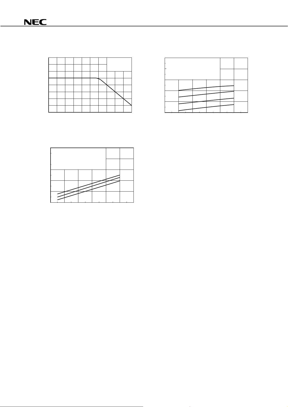
TYPICAL CHARACTERISTICS
WAVELENGTH DEPENDENCE
OF QUANTUM EFFICIENCY
100
80
η
60
40
20
Quantum Efficiency (%)
0
0.9 1.0 1.1 1.31.2 1.4 1.5 1.6 1.7
Wavelength λ ( m)
µ
REVERSE VOLTAGE DEPENDENCE
OF DARK CURRENT
10
∆
Responsivity (Relative Value) S/S (%)
TEMPERATURE DEPENDENCE
OF RESPONSIVITY
10
0
–10
–60
–40 –20 0 20
Operating Case Temperature T
TEMPERATURE DEPENDENCE
OF DARK CURRENT
1
10
0
10
–1
10
λ = 1 300 nm
40 60 80
C
(˚C)
VR = 10 V
••••
100
1.0
(nA)
D
0.1
Dark Current I
0.01
0.001
01020
Reverse Voltage V
TC = 75 ˚C
50 ˚C
25 ˚C
0 ˚C
–25 ˚C
R
(V)
–2
10
Dark Current ID (nA)
–3
10
–60 –40 –20 0
Operating Case Temperature TC (˚C)
20 40
60 80
REVERSE VOLTAGE DEPENDENCE
OF TERMINAL CAPACITANCE
5
f = 1.0 MHz
1
Terminal Capacitance Ct (pF)
0.5
0.01 0.1 1 10 100
Reverse Voltage V
R (V)
100
3
Page 4
NDL5481P Series
FREQUENCY RESPONSE
VR = 10 V
λ = 1 300 nm
RL = 50 Ω
Response (3dB/div.)
0 2.5 5.0
Frequency f (GHz)
OPTICAL INPUT POWER vs. IMD2
0
2 LD, 2 Tone Test
–20
f = 187.25 MHz, 193.25 MHz
R = 10 V, λ = 1 300 nm
V
–40
–60
IMD2 (dBc)
OMI
90%
70%
50%
0
2 LD, 2 Tone Test
–20
f = 187.25 MHz, 193.25 MHz
V
–40
–60
IMD2 (dBc)
–80
–100
40
MODULATION INDEX vs. IMD2
R
= 10 V, λ = 1 300 nm
P
+6 dBm
+3 dBm
–3 dBm
50
60
Modulation Index (%)
80 90 100
70
in
0 dBm
–80
–100
–4
–2
0
Optical Input Power Pin (dBm)
468
2
4
Page 5
NDL5481P Series
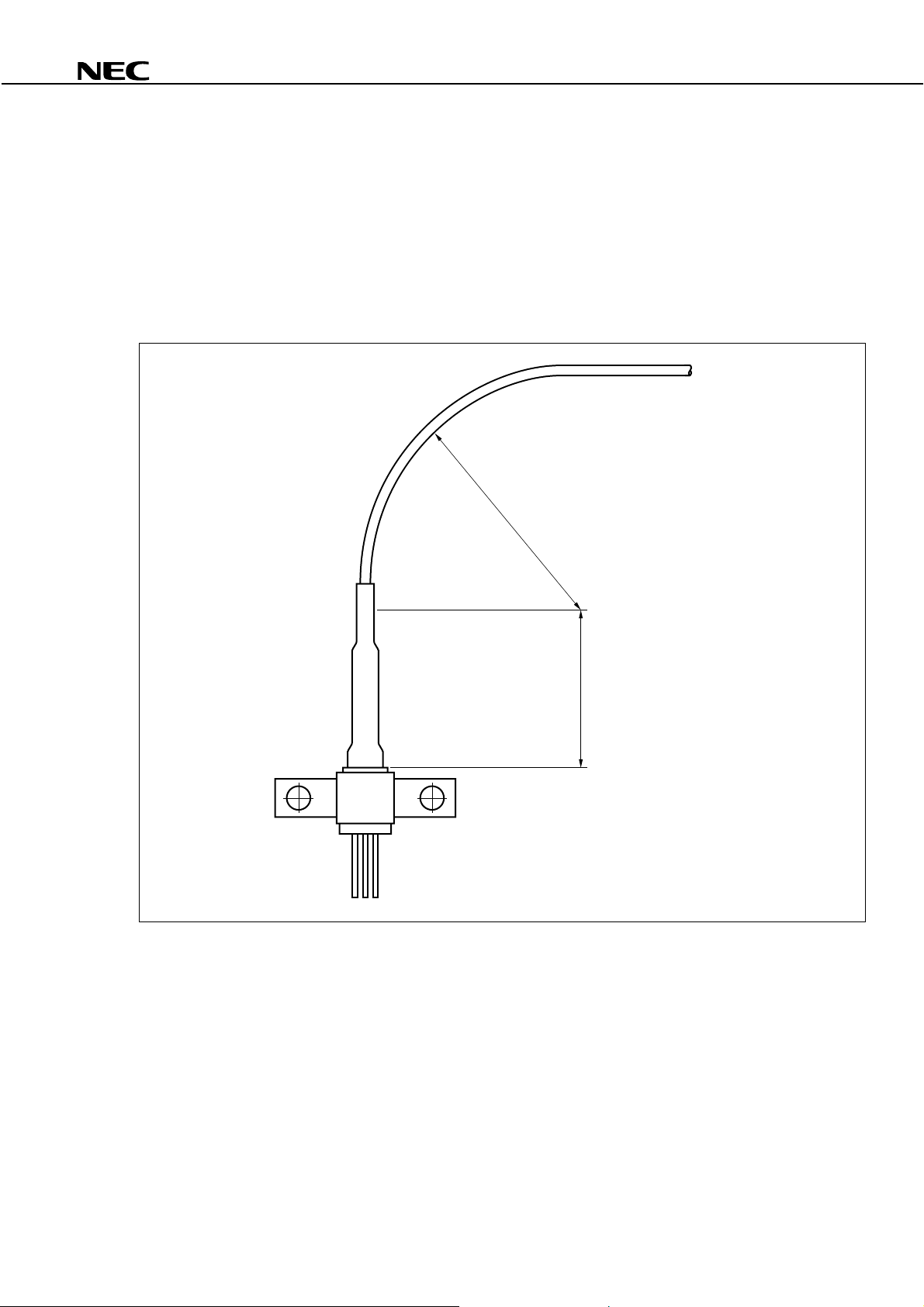
HANDLING PRECAUTION for PD/APD MODULE
The NEC PD/APD module has heat shrink tubing to protect the ferrule edge (*1) and the junction between the
ferrule and the module body (*2). In order to avoid breaking the fiber and/or optical coupling degradation, NEC
recommends the following handling precautions.
1. Do not make the fiber bend radius less than 30 mm (*3).
2. Do not bend the fiber within the 18 mm section from the module body (*4).
3. Do not stress the ferrule with a lateral force exceeding 500 g (*5).
30 mm min (*3)
fiber
•
(*1)
ferrule (*5)
(*2)
module body
18 mm min (*4)
5
Page 6
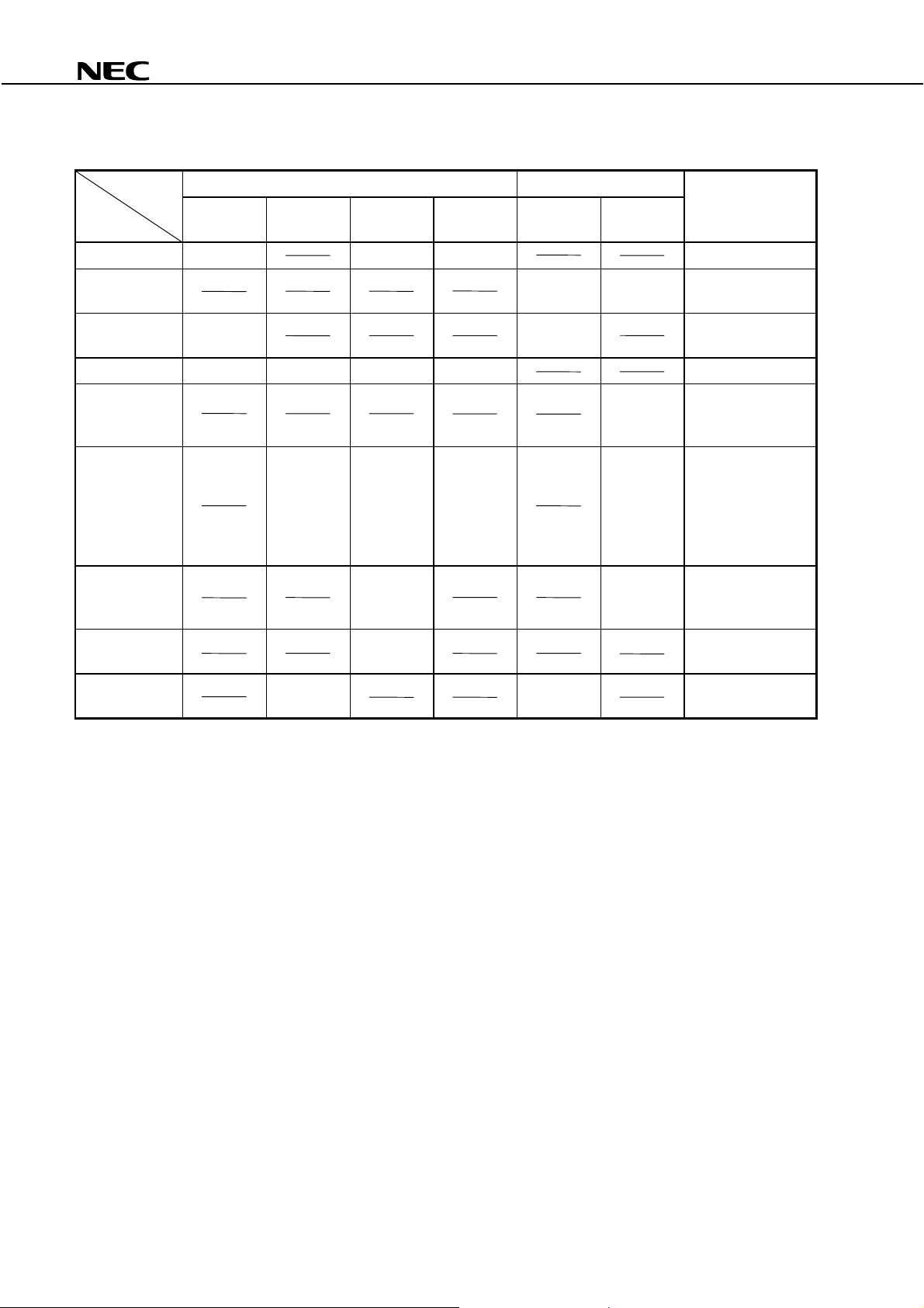
InGaAs APD/PD FAMILY
••••
Features APD PIN-PD
30 µm
φ
Packages
TO-18 type Can NDL5530 NDL5500 NDL5510 3 pins
TO-18 type Can
with Micro Lens
Small Can
5.6 µm
φ
Chip on Carrier NDL5530C NDL5520C NDL5500C NDL5510C
Receptacle Module NDL5471RC
Coaxial Module with
MMF
Coaxial Module with
SMF
14-pin DIP Module
with TEC
6-pin BFY Module
with MMF
(for 2.5 Gb/s)
NDL5531
50 µm
φ
(for 2.5 Gb/s)
NDL5521P
NDL5521P1
NDL5521P2
NDL5522P NDL5422P With Pre-AMP
50 µm
φ
NDL5551P
NDL5551P1
NDL5551P2
NDL5553P
NDL5553P1
NDL5553P2
NDL5553PS
NDL5553P1S
NDL5553P2S
NDL5506P
NDL5506PS
*1
*1
*1
*1
*1
*1
80 µm
φ
NDL5561P
NDL5561P1
NDL5561P2
*2
*2
*2
50 µm
φ
(for 2.5 Gb/s)
NDL5490L
NDL5490
*3,4
*3,4
NDL5405L
NDL5471RD
NDL5461P
NDL5461P1
NDL5461P2
NDL5481P
NDL5481P1
NDL5481P2
NDL5481P Series
80 µm
φ
*5
*5
*5
Remarks
3 pins
3 pins
RC: FC receptacle
RD: SC receptacle
P1, P2: With flange
T = 45 K (@ Ic = 1.1 A)
∆
PS: With SMF
*1
For OTDR
*2
With GI-62.5/125
*3
Under development
*4
Internal pre-amplifier for 1Gb/s
*5
For analog application (optical CATV)
Remark
Modules are available with FC-PC connector or optional SC-PC connector.
6
Page 7

NDL5481P Series
REFERENCE
Document Name Document No.
NEC semiconductor device reliabilit y/ qualit y c ontrol system IEI-1205
Quality grade on NEC semiconductor devices IEI-1209
Semiconductor devic e mounting technology manual C10535E
Semiconductor devic e package manual IEI-1213
Guide to quality assurance for semiconductor devices MEI-1202
Semiconductor sel ection guide X10679E
7
Page 8

NDL5481P Series
CAUTION
Within this device there exists GaAs (Gallium Arsenide) material which is a
harmful substance if ingested. Please do not under any circumstance break the
hermetic seal.
The export of this product from Japan is prohibited without governmental license. To export or re-export this product from
a country other than Japan may also be prohibited without a license from that country. Please call an NEC sales
representative.
No part of this document may be copied or reproduced in any form or by any means without the prior written
consent of NEC Corporation. NEC Corporation assumes no responsibility for any errors which may appear in this
document.
NEC Corporation does not assume any liability for infringement of patents, copyrights or other intellectual
property rights of third parties by or arising from use of a device described herein or any other liability arising
from use of such device. No license, either express, implied or otherwise, is granted under any patents,
copyrights or other intellectual property rights of NEC Corporation or others.
While NEC Corporation has been making continuous effort to enhance the reliability of its semiconductor devices,
the possibility of defects cannot be eliminated entirely. To minimize risks of damage or injury to persons or
property arising from a defect in an NEC semiconductor device, customer must incorporate sufficient safety
measures in its design, such as redundancy, fire-containment, and anti-failure features.
NEC devices are classified into the following three quality grades:
"Standard", "Special", and "Specific". The Specific quality grade applies only to devices developed based on
a customer designated "quality assurance program" for a specific application. The recommended applications
of a device depend on its quality grade, as indicated below. Customers must check the quality grade of each
device before using it in a particular application.
Standard: Computers, office equipment, communications equipment, test and measurement equipment,
audio and visual equipment, home electronic appliances, machine tools, personal electronic
equipment and industrial robots
Special: Transportation equipment (automobiles, trains, ships, etc.), traffic control systems, anti-disaster
systems, anti-crime systems, safety equipment and medical equipment (not specifically designed
for life support)
Specific: Aircrafts, aerospace equipment, submersible repeaters, nuclear reactor control systems, life
support systems or medical equipment for life support, etc.
The quality grade of NEC devices in "Standard" unless otherwise specified in NEC's Data Sheets or Data Books.
If customers intend to use NEC devices for applications other than those specified for Standard quality grade,
they should contact NEC Sales Representative in advance.
Anti-radioactive design is not implemented in this product.
M4 94. 11
 Loading...