

Page 1
Inductive sensor NCB15-30GM40-N0
Technical Data
General specifications
Switching function Normally closed (NC)
Output type NAMUR
Rated operating distance sn15 mm
Installation quasi flush
Assured operating distance sa0 ... 12.15 mm
0102
Model Number
NCB15-30GM40-N0
Features
• 15 mm quasi flush
• Usable up to SIL 2 acc. to IEC 61508
Accessories
BF 30
Mounting flange, 30 mm
Actual operating distance s
Reduction factor rAl 0.33
Reduction factor r
Reduction factor r
Output type 2-wire
Nominal ratings
Nominal voltage Uo8 V
Switching frequency f 0 ... 450 Hz
Hysteresis H 1 ... 15 typ. 5 %
Reverse polarity protection reverse polarity protected
Short-circuit protection yes
Current consumption
Measuring plate not detected
Measuring plate detected
Switching state indicator LED, yellow
Functional safety related parameters
MTTFd 3068 a
Mission Time (TM) 20 a
Diagnostic Coverage (DC) 0 %
Ambient conditions
Ambient temperature -25 ... 100 °C (-13 ... 212 °F)
Storage temperature -40 ... 100 °C (-40 ... 212 °F)
Mechanical specifications
Connection type cable PVC , 2 m
Core cross-section 0.75 mm
Housing material Stainless steel 1.4305 / AISI 303
Sensing face PBT
Degree of protection IP66 / IP67
Cable
Bending radius
General information
Use in the hazardous area see instruction manuals
Category
Compliance with standards and
directives
Standard conformity
NAMUR
Electromagnetic compatibility
Standards
Approvals and certificates
EAC conformity TR CU 012/2011
FM approval
Control drawing
UL approval cULus Listed, General Purpose
CSA approval cCSAus Listed, General Purpose
CCC approval CCC approval / marking not required for products rated ≤36 V
0.29
Cu
0.76
304
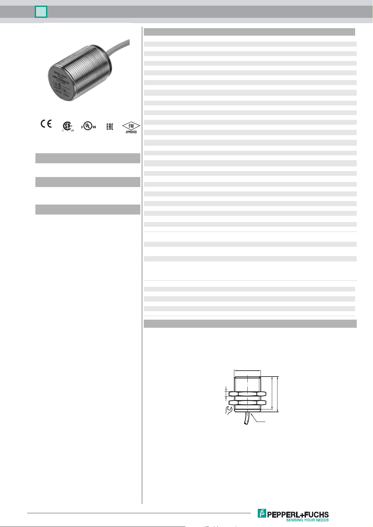
Dimensions
13.5 ... 16.5 mm typ.
r
≥ 2.2 mA
≤ 1 mA
2
> 10 x cable diameter
1G; 2G; 3G; 1D; 3D
EN 60947-5-6:2000
IEC 60947-5-6:1999
NE 21:2007
EN 60947-5-2:2007
EN 60947-5-2/A1:2012
IEC 60947-5-2:2007
IEC 60947-5-2 AMD 1:2012
116-0165
Release date: 2018-04-19 08:11 Date of issue: 2018-04-19 181091_eng.xml
Refer to “General Notes Relating to Pepperl+Fuchs Product Information”.
M30x1,5
LED
37
40
5
36
1
Page 2
Inductive sensor NCB15-30GM40-N0
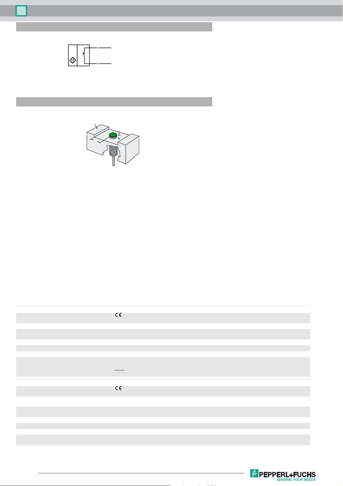
Electrical Connection
Installation Hint
BN
BU
L+
L-
Installation conditions
Metal
A
B
A = 5 mm
B = 15 mm
Equipment protection level Ga
CE marking 0102
ATEX marking ¬ II 1G Ex ia IIC T6…T1 Ga The Ex-related marking can also be printed on the enclosed label.
Standards EN 60079-0:2012+A11:2013 EN 60079-11:2012 Ignition protection "Intrinsic safety"
Appropriate type NCB15-30GM...-N0...
Effective internal inductivity C
Effective internal inductance L
Ambient temperature Details of the correlation between the type of circuit connected, the maximum permissible ambient temperature, the
Equipment protection level Gb
CE marking 0102
ATEX marking ¬ II 1G Ex ia IIC T6…T1 Ga
Standards EN 60079-0:2012+A11:2013 EN 60079-11:2012 Ignition protection "Intrinsic safety"
Appropriate type NCB15-30GM...-N0...
Effective internal inductivity C
Effective internal inductance L
Maximum permissible ambient temperature T
Refer to “General Notes Relating to Pepperl+Fuchs Product Information”.
i
i
i
i
Use is restricted to the following stated conditions
≤ 120 nF ; a cable length of 10 m is considered.
≤ 150 µH ; a cable length of 10 m is considered.
temperature class, and the effective internal reactance values can be found on the EC-type examination certificate.
Note:
Use the temperature table for category 1 !!! The 20 % reduction in accordance with EN 1127-1 has already
been applied to the temperature table for category 1.
The Ex-significant identification is on the enclosed adhesive label
Use is restricted to the following stated conditions
≤ 120 nF ; a cable length of 10 m is considered.
≤ 150 µH ; a cable length of 10 m is considered.
Details of the correlation between the type of circuit connected, the maximum permissible ambient temperature, the
amb
temperature class, and the effective internal reactance values can be found on the EC-type examination certificate.
2
Release date: 2018-04-19 08:11 Date of issue: 2018-04-19 181091_eng.xml
Page 3

Inductive sensor NCB15-30GM40-N0
Equipment protection level Gc (ic)
Certificate PF 13 CERT 2895 X
CE marking
ATEX marking ¬ II 3G Ex ic IIC T6…T1 Gc
Standards EN 60079-0:2012+A11:2013 EN 60079-11:2012 Ignition protection category "ic" Use is restricted to the following
Effective internal inductivity C
Effective internal inductance L
Special conditions
for Pi=34 mW, Ii=25 mA, T6
for Pi=34 mW, Ii=25 mA, T5
for Pi=34 mW, Ii=25 mA, T4-T1
for Pi=64 mW, Ii=25 mA, T6
for Pi=64 mW, Ii=25 mA, T5
for Pi=64 mW, Ii=25 mA, T4-T1
for Pi=169 mW, Ii=52 mA, T6
for Pi=169 mW, Ii=52 mA, T5
for Pi=169 mW, Ii=52 mA, T4-T1
for Pi=242 mW, Ii=76 mA, T6
for Pi=242 mW, Ii=76 mA, T5
for Pi=242 mW, Ii=76 mA, T4-T1
Equipment protection level Gc (nL)
Standard conformity EN 60079-15:2005 Ignition protection category "n"
Effective internal capacitance C
Effective internal inductance Li ≤ 150 µH ; A cable length of 10 m is considered.
General The apparatus has to be operated according to the appropriate data in the data sheet and in this instruction manual.
Special conditions
for Pi=34 mW, Ii=25 mA, T6
for Pi=34 mW, Ii=25 mA, T5
for Pi=34 mW, Ii=25 mA, T4-T1
for Pi=64 mW, Ii=25 mA, T6
for Pi=64 mW, Ii=25 mA, T5
for Pi=64 mW, Ii=25 mA, T4-T1
for Pi=169 mW, Ii=52 mA, T6
for Pi=169 mW, Ii=52 mA, T5
for Pi=169 mW, Ii=52 mA, T4-T1
for Pi=242 mW, Ii=76 mA, T6
for Pi=242 mW, Ii=76 mA, T5
for Pi=242 mW, Ii=76 mA, T4-T1
i
i
≤ 120 nF ; a cable length of 10 m is considered.
i
The Ex-significant identification is on the enclosed adhesive label
stated conditions
≤ 120 nF ; a cable length of 10 m is considered.
≤ 150 µH ; A cable length of 10 m is considered.
55 °C (131 °F)
55 °C (131 °F)
55 °C (131 °F)
55 °C (131 °F)
55 °C (131 °F)
55 °C (131 °F)
41 °C (105.8 °F)
41 °C (105.8 °F)
41 °C (105.8 °F)
29 °C (84.2 °F)
29 °C (84.2 °F)
29 °C (84.2 °F)
Use is restricted to the following stated conditions
The data stated in the data sheet are restricted by this operating instruction!
The special conditions must be observed!
The ATEX Directive applies only to the use of apparatus under atmospheric conditions.
If you use the device outside atmospheric conditions, consider that the permissible safety parameters should be
reduced.
55 °C (131 °F)
55 °C (131 °F)
55 °C (131 °F)
55 °C (131 °F)
55 °C (131 °F)
55 °C (131 °F)
41 °C (105.8 °F)
41 °C (105.8 °F)
41 °C (105.8 °F)
29 °C (84.2 °F)
29 °C (84.2 °F)
29 °C (84.2 °F)
Equipment protection level Da
CE marking 0102
ATEX marking ¬ II 1D Ex ia IIIC T135°C Da The Ex-related marking can also be printed on the enclosed label.
Standards EN 60079-0:2012+A11:2013 EN 60079-11:2012 Ignition protection "Intrinsic safety"
Appropriate type NCB15-30GM...-N0...
Effective internal inductivity C
Effective internal inductance L
Maximum permissible ambient temperature T
Equipment protection level Dc
CE marking 0102
ATEX marking ¬ II 3D IP67 T 111 °C (231.8 °F) X
Standards EN 50281-1-1
Special conditions
Maximum heating (Temperature rise)
at U
using an amplifier in accordance with EN 609475-6
Release date: 2018-04-19 08:11 Date of issue: 2018-04-19 181091_eng.xml
Refer to “General Notes Relating to Pepperl+Fuchs Product Information”.
=9 V, RV=562 Ω
Bmax
i
i
Use is restricted to the following stated conditions
≤ 120 nF A cable length of 10 m is considered.
≤ 150 µH A cable length of 10 m is considered.
Details of the correlation between the type of circuit connected, the maximum permissible ambient temperature, the
amb
surface temperature, and the effective internal reactance values can be found on the EC-type-examination
certificate.
The maximum permissible ambient temperature of the data sheet must be noted, in addition, the lower of
the two values must be maintained.
Protection via housing
Use is restricted to the following stated conditions
Values can be obtained from the following list, depending on the max. operating voltage Ub max and the minimum
series resistance Rv.
11 K
11 K
3
Page 4

Inductive sensor NCB15-30GM40-N0
Equipment protection level Dc (tc)
CE marking
ATEX marking ¬ II 3D Ex tc IIIC T80°C Dc
Standards EN 60079-0:2012+A11:2013, EN 60079-31:2014
General The corresponding datasheets, declarations of conformity, EC-type examination certificates, certifications, and
Special conditions
Maximum permissible ambient temperature T
at U
using an amplifier in accordance with EN 609475-6
Equipment protection level Dc (tD)
General The apparatus has to be operated according to the appropriate data in the data sheet and in this instruction manual.
Special conditions
Minimum series resistance RV
Maximum permissible ambient temperature T
at U
using an amplifier in accordance with EN 609475-6
=9 V, RV=562 Ω
Bmax
=9 V, RV=562 Ω
Bmax
The Ex-related marking can also be printed on the enclosed label.
Protection by enclosure "tc" Some of the information in this instruction manual is more specific than the information
provided in the datasheet.
control draw see datasheets), form an integral part of this document. These documents can
be found at The maximum surface temperature of the device was determined without a
layer of dust of the information in this instruction manual is more specific than the
information provided in the datasheet.
Values can be obtained from the following list, depending on the max. operating voltage Ub max and the minimum
Umax
series resistance Rv.
58 °C (136.4 °F)
58 °C (136.4 °F)
The maximum surface temperature has been determined in accordance with method A without a dust layer on the
equipment.
The data stated in the data sheet are restricted by this operating instruction!
The special conditions must be adhered to!
A minimum series resistance RV is to be provided between the power supply voltage and the proximity switch in
accordance with the following list. This can also be assured by using a switch amplifier.
Values can be obtained from the following list, depending on the max. operating voltage Ub max and the minimum
Umax
series resistance Rv.
58 °C (136.4 °F)
58 °C (136.4 °F)
Release date: 2018-04-19 08:11 Date of issue: 2018-04-19 181091_eng.xml
Refer to “General Notes Relating to Pepperl+Fuchs Product Information”.
4
 Loading...