

Page 1
Inductive power clamp sensor NBN2-F58E-100S3-E8-V1
Technical Data
General specifications
Switching function 2 x normally open (NO)
Output type PNP
Rated operating distance sn2 mm
Installation non-flush
Output polarity DC
Model Number
NBN2-F58E-100S3-E8-V1
Features
• Extremely bright triple luminous band
indication
• For use in direct- and alternating-field
welding systems
• Completely halogen and silicon free
Accessories
V1-G-OR2M-POC
Female cordset, M12, 4-pin, TPE cable, welding-bead
resistant
V1-G-2M-PUR-H/S
Female cordset, M12, 4-pin, irradiated PUR cable
V1-W-2M-PUR-H/S
Female cordset, M12, 4-pin, irradiated PUR cable
Assured operating distance s
Reduction factor rAl 0.35
Reduction factor r
Reduction factor r
Reduction factor r
Output type 4-wire
Nominal ratings
Operating voltage UB10 ... 30 V
Switching frequency f 0 ... 100 Hz
Reverse polarity protection reverse polarity protected
Short-circuit protection pulsing
Voltage drop Ud≤ 3 V
Rated insulation voltage U
Operating current I
Off-state current I
No-load supply current I
Constant magnetic field B 100 mT
Alternating magnetic field B 100 mT
Tuning-out typically 1 s
Operating voltage indicator LED green
Switching state indicator Switching state "closed" = LED red (S2)
Functional safety related parameters
MTTFd 1445 a
Mission Time (TM) 20 a
Diagnostic Coverage (DC) 0 %
Ambient conditions
Ambient temperature -25 ... 50 °C (-13 ... 122 °F)
Storage temperature -40 ... 85 °C (-40 ... 185 °F)
Mechanical specifications
Connection type Connector plug M12 x 1 , 4-pin
Flexible lead, housing-sensor PUR (halogen-free)
Housing material amplifier; PBT, PA6 + GD-ZN AL4
Degree of protection IP65
Protection class II
Compliance with standards and
directives
Standard conformity
Standards
Approvals and certificates
UL approval UL Recognized
CCC approval CCC approval / marking not required for products rated ≤36 V
0.35
Cu
0.7
304
0.45
Brass
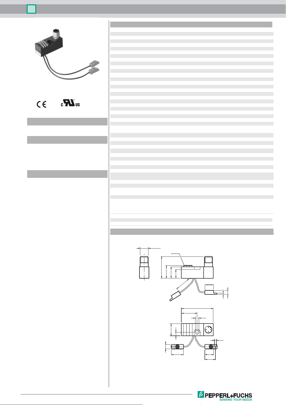
Dimensions
0 ... 1.62 mm
a
60 V
BIS
0 ... 100 mA
L
0 ... 0.5 mA typ. 0.1 µA at 25 °C
r
≤ 15 mA
0
switching state "open" = LED yellow (S1)
oscillators; PBT
EN 60947-5-2:2007
EN 60947-5-2/A1:2012
IEC 60947-5-2:2007
IEC 60947-5-2 AMD 1:2012
Release date: 2018-07-27 07:17 Date of issue: 2018-07-27 297908_eng.xml
Refer to “General Notes Relating to Pepperl+Fuchs Product Information”.
M12 x 1
LEDs
YEGNRD
32
20.5
18.5
14.5
100
±5
13
2
6
46.5
23.5
5.3
18
5
2.8
6.5
1318
15.5
1
Page 2

Inductive power clamp sensor NBN2-F58E-100S3-E8-V1
Electrical Connection
Pinout
1
I
II
Wire colors in accordance with EN 60947-5-2
1 BN
2 WH
3 BU
4 BK
4
I
2
II
3
2
L+
L-
1
4
3
(brown)
(white)
(blue)
(black)
Release date: 2018-07-27 07:17 Date of issue: 2018-07-27 297908_eng.xml
Refer to “General Notes Relating to Pepperl+Fuchs Product Information”.
2
Page 3

Inductive power clamp sensor NBN2-F58E-100S3-E8-V1
Safety instructions
Laws and/or regulations and standards
governing the use or intended usage goal
must be observed.
No changes can be made to the device.
Repairs are not possible.
Protection class II (protective isolation)
is only reached under the stated
mounting conditions.
Release date: 2018-07-27 07:17 Date of issue: 2018-07-27 297908_eng.xml
Refer to “General Notes Relating to Pepperl+Fuchs Product Information”.
3
 Loading...