

Page 1
Inductive sensor NBB8-18GM60-B3-V1
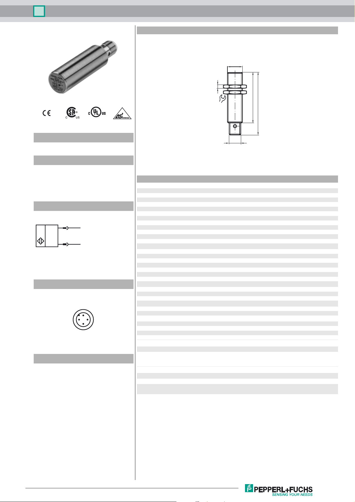
Dimensions
M18x1
4
Model Number
NBB8-18GM60-B3-V1
Features
• Basic series
• 8 mm embeddable
• Cylindrical
• NO/NC selectable
• On/Off delay (disconnectable)
Connection
1
3
(+)
(-)
Pinout
1
2
4
3
Accessories
EXG-18
Quick mounting bracket with dead stop
24
M12x1
60
75
Technical Data
General specifications
Switching element function NO/NC programmable
Rated operating distance s
Installation embeddable
Output polarity AS-Interface
Assured operating distance sa0 ... 6.48 mm
Reduction factor r
Reduction factor rCu 0.4
Reduction factor r
Reduction factor r
Slave type Standard slave
AS-Interface specification V2.1
Required master specification ≥ V2.0
Nominal ratings
Operating voltage UB26.5 ... 31.9 V via AS-i bus system
Switching frequency f 0 ... 200 Hz
Hysteresis H 1 ... 15 typ. 5 %
Reverse polarity protected reverse polarity protected
No-load supply current I
Indication of the switching state dual-LED, yellow
Fault indication dual-LED, red
Functional safety related parameters
MTTFd 926 a
Mission Time (TM) 20 a
Diagnostic Coverage (DC) 0 %
Ambient conditions
Ambient temperature -25 ... 70 °C (-13 ... 158 °F)
Storage temperature -40 ... 85 °C (-40 ... 185 °F)
Mechanical specifications
Connection type connector M12 x 1, 4-pin
Housing material brass, nickel-plated
Sensing face PBT
Protection degree IP67
Compliance with standards and directives
Standard conformity
Standards
Approvals and certificates
UL approval cULus Listed, General Purpose
CSA approval cCSAus Listed, General Purpose
CCC approval Products with a maximum operating voltage of ≤36 V do not bear a
0.4
Al
0.7
304
0.5
Brass
8 mm
n
≤ 25 mA
0
EN 60947-5-2:2007
IEC 60947-5-2:2007
EN 50295:1999
CCC marking because they do not require approval.
Release date: 2012-04-10 15:22 Date of issue: 2012-04-10 226335_eng.xml
Subject to modifications without notice
Copyright Pepperl+Fuchs
1
Page 2

Inductive sensor NBB8-18GM60-B3-V1
Programming Instructions
Adress 00 preset, alterable
via Busmaster
or programming units
IO-Code 1
ID-Code 1
Data bit
Bit Function
D0 Switching state
D1 not used
D2 not used
D3 not used
Paramet er b it
Bit Function
P0 ON / Off delay
activated* / deactivated
P1 Switching element function
NO* / NC
P2 not used
P3 not used
*Standard setting
Release date: 2012-04-10 15:22 Date of issue: 2012-04-10 226335_eng.xml
Subject to modifications without notice
Copyright Pepperl+Fuchs
2
 Loading...