

Page 1
Inductive sensor NBB4-F1-E2
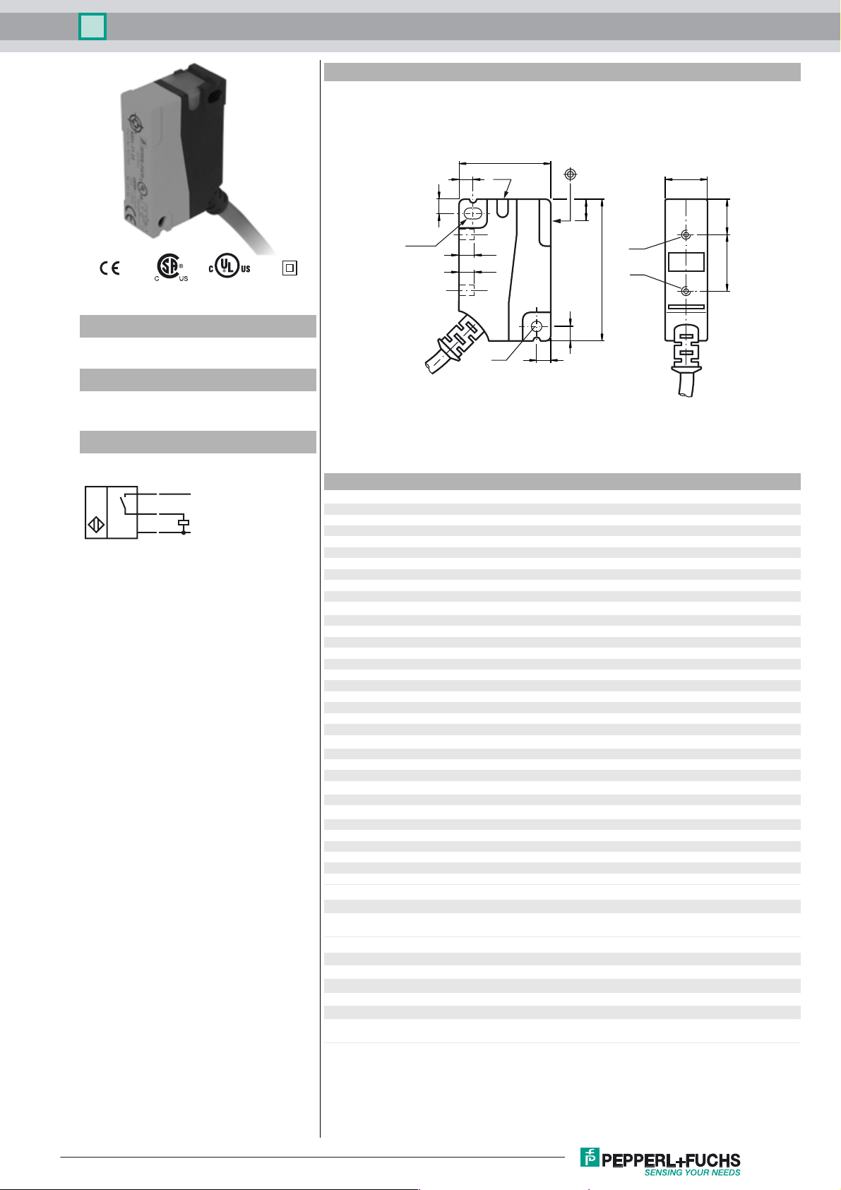
Dimensions
26
4
LED
12
Model Number
NBB4-F1-E2
Features
•4 mm flush
•3-wire DC
Connection
BN
BK
BU
3.2 x 5
4
4.5
4.5
6
1016
M3
M3
40
4
3.2
4
Technical Data
L+
L-
General specifications
Switching element function PNP NO
Rated operating distance s
Installation flush
Output polarity DC
Assured operating distance sa0 ... 3.24 mm
Reduction factor r
Reduction factor rCu 0.45
Reduction factor r
Reduction factor r
Nominal ratings
Operating voltage UB10 ... 30 V DC
Switching frequency f 0 ... 1400 Hz
Hysteresis H typ. 5%
Reverse polarity protected reverse polarity protected
Short-circuit protection pulsing
Voltage drop U
Rated insulation voltage U
Operating current I
Off-state current I
No-load supply current I
Indication of the switching state LED, yellow
Functional safety related parameters
MTTFd 1640 a
Mission Time (T
Diagnostic Coverage (DC) 0 %
Ambient conditions
Ambient temperature -25 ... 70 °C (-13 ... 158 °F)
Mechanical specifications
Connection type cable PVC , 2 m
Core cross-section 0.5 mm
Housing material PA
Sensing face PA
Protection degree IP67
Tightening torque, fastening screws Threading M3 max: 1.1 Nm
Compliance with standards and directives
Standard conformity
Standards
Approvals and certificates
Protection class II
Rated insulation voltage U
Design-impulse-voltage withstand U
UL approval cULus Listed, General Purpose
CSA approval cCSAus Listed, General Purpose
CCC approval Products with a maximum operating voltage of ≤36 V do not bear a
0.4
Al
0.8
304
0.55
Brass
) 20 a
M
4 mm
n
≤ 2.5 V
d
60 V
BIS
0 ... 250 mA
L
0 ... 0.01 mA typ. 0.1 µA at 25 °C
r
≤ 15 mA
0
2
EN 60947-5-2:2007
IEC 60947-5-2:2007
60 V
i
800 V
imp
CCC marking because they do not require approval.
Release date: 2012-06-04 10:29 Date of issue: 2012-06-04 184367_eng.xml
Subject to modifications without notice
Copyright Pepperl+Fuchs
1
 Loading...