

Page 1
Inductive sensor NBB20-U1-A0-M
Technical Data
General specifications
Switching element function NPN NO/NC
S
Model Number
NBB20-U1-A0-M
Features
• Sensor head bidirectional and rotatable
• 20 mm flush
• E1-Type approval
• Extended temperature range 40 ... +85 °C
• 4 LEDs indicator for 360° visibility
Accessories
MHW 01
Modular mounting bracket
E 1
Rated operating distance s
Installation flush
Output polarity DC
Assured operating distance sa0 ... 16.2 mm
Actual operating distance s
Reduction factor rAl 0.34
Reduction factor r
Reduction factor r
Reduction factor r
Reduction factor r
Nominal ratings
Operating voltage UB10 ... 60 V DC
Switching frequency f 0 ... 200 Hz
Hysteresis H typ. 5 %
Reverse polarity protection reverse polarity protected
Short-circuit protection pulsing
Vol tag e d rop U
Operating current I
Off-state current I
No-load supply current I
Operating voltage indicator LED, green
Switching state indicator LED, yellow
Functional safety related parameters
MTTFd 670 a
Mission Time (T
Diagnostic Coverage (DC) 0 %
Ambient conditions
Ambient temperature -40 ... 85 °C (-40 ... 185 °F)
Mechanical specifications
Connection type screw terminals
Information for connection A maximum of two conductors with the same core cross-section
Core cross-section up to 2.5 mm
Minimum core cross-section
Maximum core cross-section
Housing material PA/metal with epoxy powder coating
Sensing face PA -G F 35
Housing base plastic
Degree of protection IP68 / IP69K
Mass 225 g
Note Tightening torque: 1.8 Nm (housing)
Compliance with standards and directives
Stan dard conf ormit y
Sta ndar ds
Approvals and certificates
UL approval cULus Listed, General Purpose
CSA approval cCSAus Listed, General Purpose
CCC approval Certified by China Compulsory Certification (CCC)
E1 Type approval 10R-04
0.32
Cu
0.77
304
1
St37
0.43
Brass
) 20 a
M
20 mm
n
18 ... 22 mm typ. 20 mm
r
≤ 2 V
d
0 ... 200 mA
L
0 ... 0.5 mA
r
≤ 20 mA
0
may be mounted on one terminal connection!
tightening torque 1.2 Nm + 10 %
without wire end ferrule 0.5 mm
without wire end ferrule 2.5 mm2 , with connector sleeves 1.5 mm
EN 60947-5-2:2007
IEC 60947-5-2:2007
2
2
, with connector sleeves 0.34 mm
2
2
Release date: 2016-09-29 11:33 Date of issue: 2016-10-10 207745_eng.xml
Refer to “General Notes Relating to Pepperl+Fuchs Product Information”.
1
Page 2
Inductive sensor NBB20-U1-A0-M
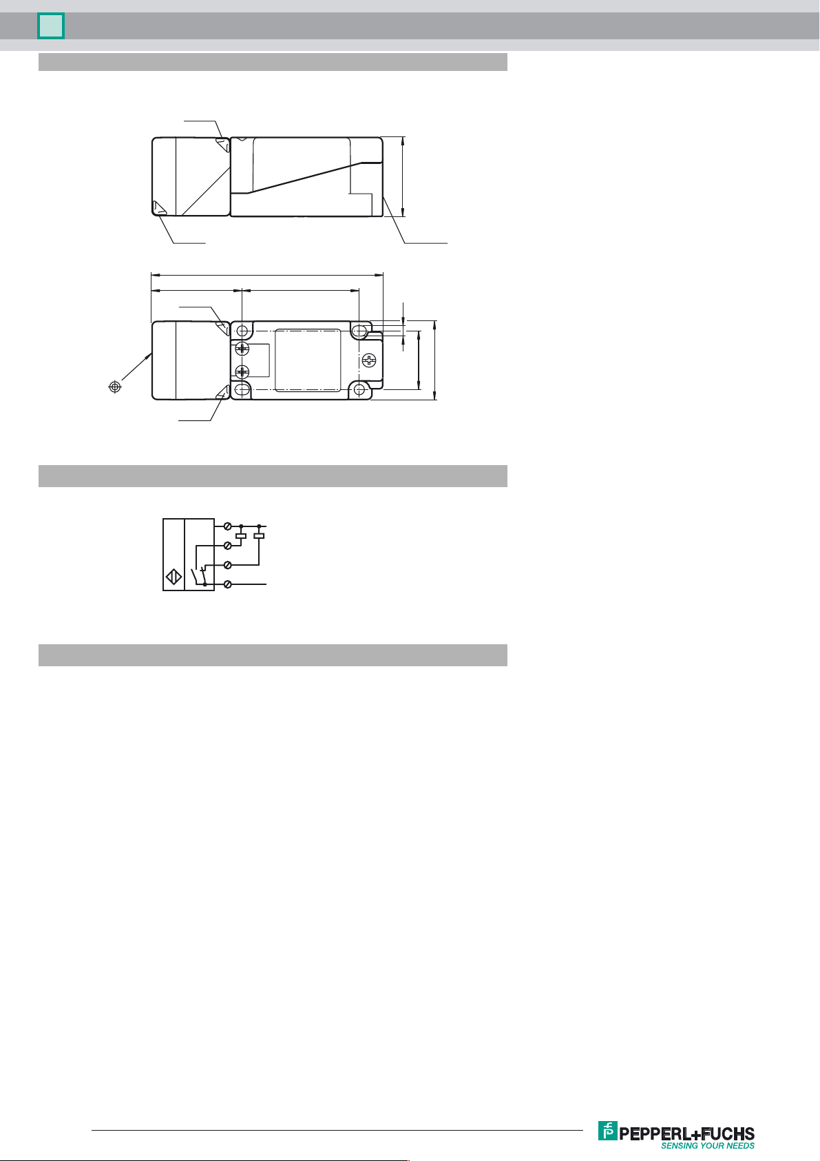
Dimensions
LED ye
40
LED gn
Electrical Connection
LED gn
LED ye
M20 x 1.5
118
6046
5.3
30
40
1
4
2
3
L+
L-
Installation Hint
Emitted interference and interference immunity in
accordance with motor vehicle directive 2006/28/EG
(e1 Type approval)
Interference immunity in accordance with
DIN ISO 11452-2: 100 V/m
Frequency band 20 MHz up to 2 GHz
Mains-borne interference in accordance with ISO
7637-2: Pulse 1 2a 2b 3 a 3b 4 5
Severity level III III III III III III IV
Failure criterion C A C A A A C
EN 61000-4-2: CD: 8 kV / AD: 15 kV
Severity level IV IV
EN 61000-4-3: 30 V/m (80...2500 MHz)
Severity level IV
EN 61000-4-4: 2 kV
Severity level III
EN 61000-4-6: 10 V (0.01...80 MHz)
Severity level III
EN 55011: Class A
Release date: 2016-09-29 11:33 Date of issue: 2016-10-10 207745_eng.xml
Refer to “General Notes Relating to Pepperl+Fuchs Product Information”.
2
 Loading...