

Page 1
Inductive sensor NBB1,5-8GM50-A2-V1
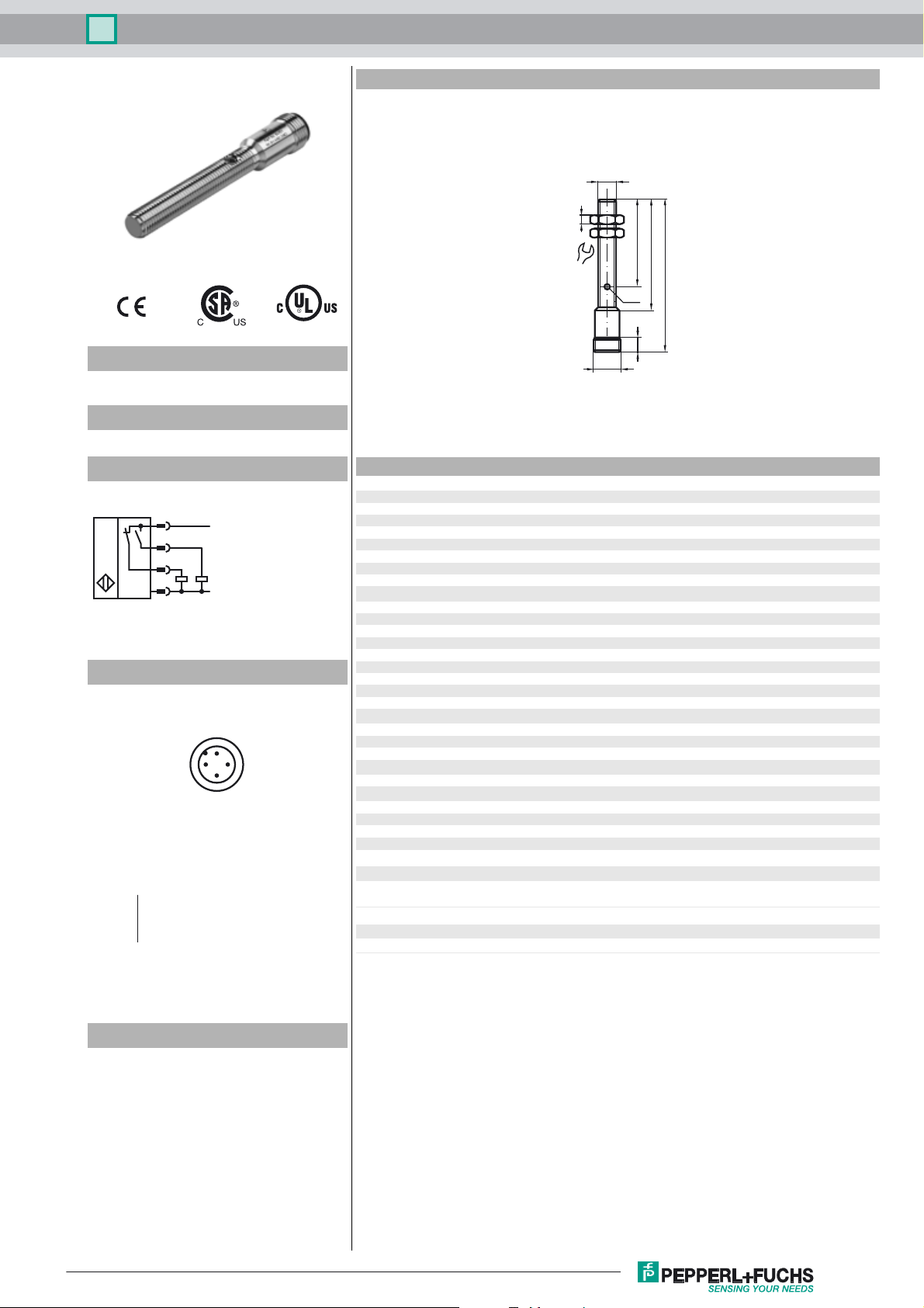
Dimensions
M8x1
4
Model Number
NBB1,5-8GM50-A2-V1
Features
• 1.5 mm flush
Connection
1
4
2
3
L+
L-
Pinout
1
2
Wire colors in accordance with EN 60947-5-2
1 BN
2 WH
3 BU
4 BK
(brown)
(white)
(blue)
(black)
4
3
LED
40
50
6
M12x1
70
13
Technical Data
General specifications
Switching element function PNP NO/NC
Rated operating distance s
Installation flush
Output polarity DC
Assured operating distance sa0 ... 1.215 mm
Reduction factor r
Reduction factor rCu 0.35
Reduction factor r
Nominal ratings
Operating voltage UB10 ... 30 V
Switching frequency f 0 ... 1500 Hz
Reverse polarity protection reverse polarity protected
Short-circuit protection pulsing
Voltage drop U
Operating current I
Off-state current I
No-load supply current I
Switching state indication LED, yellow
Functional safety related parameters
MTTFd 2660 a
Mission Time (TM) 20 a
Diagnostic Coverage (DC) 0 %
Ambient conditions
Ambient temperature -25 ... 70 °C (-13 ... 158 °F)
Mechanical specifications
Connection type Device connector M12 x 1 , 4-pin
Housing material brass, nickel-plated
Sensing face LCP
Protection degree IP67
Compliance with standards and directives
Standard conformity
Standards
Approvals and certificates
UL approval cULus Listed, General Purpose
CSA approval cCSAus Listed, General Purpose
0.45
Al
0.75
304
1. 5 m m
n
≤ 3 V
d
0 ... 100 mA
L
0 ... 0.5 mA typ. 0.1 µA at 25 °C
r
≤ 20 mA
0
EN 60947-5-2:2007
IEC 60947-5-2:2007
Accessories
BF 8
Mounting flange, 8 mm
V1-G
4-pin, M12 female field-attachable connector
V1-W
4-pin, M12 female field-attachable connector
V1-G-2M-PUR
Cable socket, M12, 4-pin, PUR cable
V1-W-2M-PUR
Cable socket, M12, 4-pin, PUR cable
EXG-08
Quick mounting bracket with dead stop
Release date: 2013-02-18 08:43 Date of issue: 2013-02-18 089953_eng.xml
Subject to modifications without notice
Copyright Pepperl+Fuchs
1
 Loading...