

Page 1
Inductive sensor NBB15-30GM50-E1-V1-M1
Technical Data
General specifications
Switching function Normally closed (NC)
Output type NPN
Rated operating distance sn15 mm
Installation flush
Output polarity DC
E
Model Number
NBB15-30GM50-E1-V1-M1
Features
• 15 mm flush
• Increased operating distance
• Extended temperature range
-40 ... +85 °C
• With increased sealing, protection
class
IP68 / IP69K
• E1-Type approval
Accessories
BF 30
Mounting flange, 30 mm
V1-G
Female connector, M12, 4-pin, field attachable
V1-W
Female connector, M12, 4-pin, field attachable
V1-G-2M-PUR
Female cordset, M12, 4-pin, PUR cable
V1-W-2M-PUR
Female cordset, M12, 4-pin, PUR cable
Assured operating distance s
Actuating element mild steel, e. g. 1.0037, SR235JR (formerly St37-2)
Reduction factor r
Reduction factor rCu 0.4
Reduction factor r
Reduction factor r
Output type 3-wire
Nominal ratings
Operating voltage UB7 ... 30 V
Switching frequency f 0 ... 1400 Hz
Hysteresis H typ. 5%
Reverse polarity protection reverse polarity protected
Short-circuit protection pulsing
1
Voltage drop Ud≤ 2 V
Operating current I
Off-state current I
No-load supply current I
Time delay before availability t
Switching state indicator LED, yellow
Functional safety related parameters
MTTFd 1494 a
Mission Time (TM) 20 a
Diagnostic Coverage (DC) 0 %
Ambient conditions
Ambient temperature -40 ... 85 °C (-40 ... 185 °F)
Storage temperature -40 ... 85 °C (-40 ... 185 °F)
Mechanical specifications
Connection type Connector M12 x 1 , 3-pin
Housing material brass, nickel-plated
Sensing face PBT
Degree of protection IP68 / IP69K
Mass 115 g
General information
Scope of delivery 2 self locking nuts in scope of delivery
Compliance with standards and
directives
Standard conformity
Standards
Approvals and certificates
UL approval cULus Listed, General Purpose, Class 2 Power Source
CCC approval CCC approval / marking not required for products rated ≤36 V
E1 Type approval 10R-04
0.45
Al
0.7
304
0.5
Brass
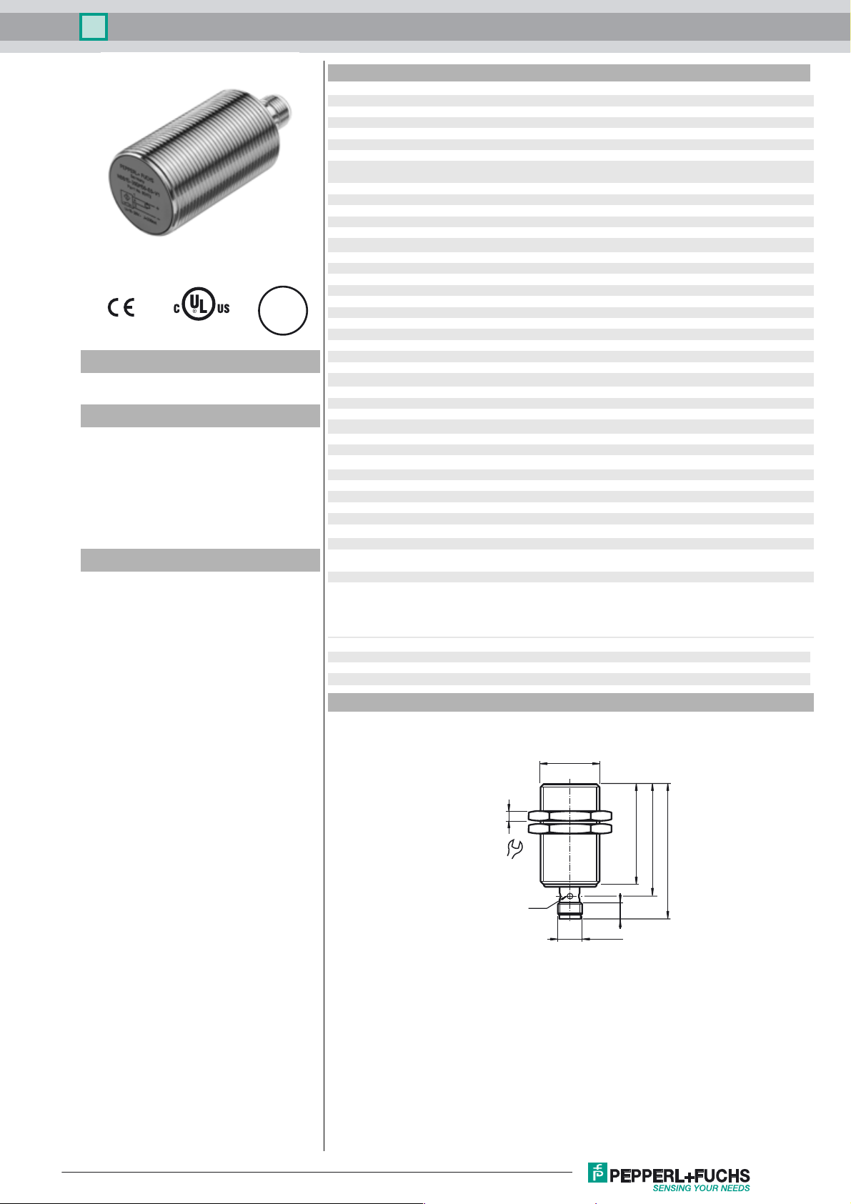
Dimensions
0 ... 12.15 mm
a
45 mm x 45 mm x 1 mm
0 ... 200 mA
L
0 ... 0.5 mA typ. 4 µA at 25 °C
r
≤ 10 mA
0
≤ 100 ms
v
EN 60947-5-2:2007
EN 60947-5-2/A1:2012
IEC 60947-5-2:2007
IEC 60947-5-2 AMD 1:2012
EN 12895: 2015
Release date: 2017-09-18 08:39 Date of issue: 2017-09-18 293454-0033_eng.xml
Refer to “General Notes Relating to Pepperl+Fuchs Product Information”.
M30 x 1.5
5
50
55
36
LED
8
M12 x 1
66
1
Page 2
Inductive sensor NBB15-30GM50-E1-V1-M1
Electrical Connection
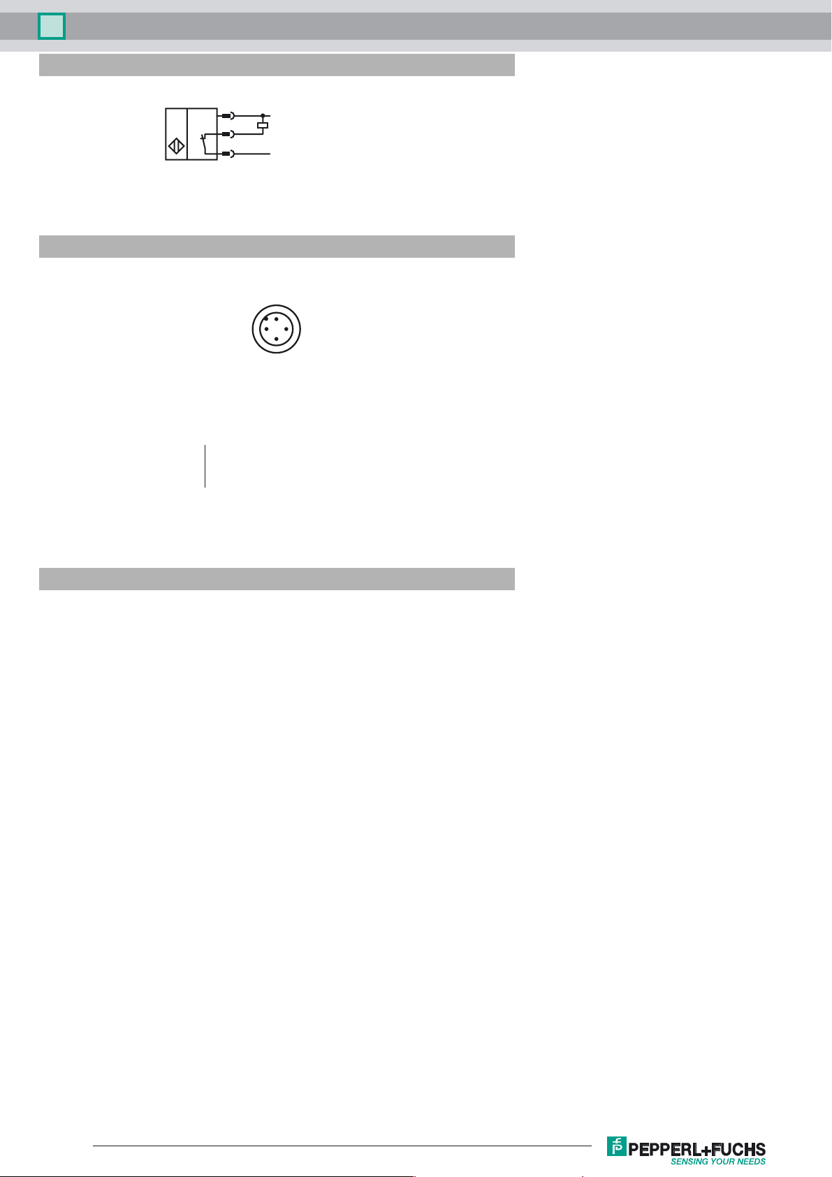
Pinout
1
4
3
Wire colors in accordance with EN 60947-5-2
1 BN
2 WH
3 BU
4 BK
2
L+
L-
1
4
3
(brown)
(white)
(blue)
(black)
Installation Hint
Mains-borne interference in accordance with ISO
7637-2:
Pulse 1 2a 2b 3a 3b 4
Severity level III III III III III III
Failure criterion A A C A A C
EN 61000-4-2: CD: 8 kV / AD: 15 kV
Severity level IV IV
EN 61000-4-3: 36 V/m (80...2500 MHz)
Severity level IV
EN 61000-4-4: 2 kV
Severity level III
EN 61000-4-6: 30 V (0.01...80 MHz)
Severity level III
EN 55011: Class A
Release date: 2017-09-18 08:39 Date of issue: 2017-09-18 293454-0033_eng.xml
Refer to “General Notes Relating to Pepperl+Fuchs Product Information”.
2
 Loading...