

Page 1
October 1994 Order Number: 231244-006
82C54
CHMOS PROGRAMMABLE INTERVAL TIMER
Y
Compatible with all Intel and most
other microprocessors
Y
High Speed, ‘‘Zero Wait State’’
Operation with 8 MHz 8086/88 and
80186/188
Y
Handles Inputs from DC
Ð 10 MHz for 82C54-2
Y
Available in EXPRESS
Ð Standard Temperature Range
Ð Extended Temperature Range
Y
Three independent 16-bit counters
Y
Low Power CHMOS
ÐI
CC
e
10 mA@8 MHz Count
frequency
Y
Completely TTL Compatible
Y
Six Programmable Counter Modes
Y
Binary or BCD counting
Y
Status Read Back Command
Y
Available in 24-Pin DIP and 28-Pin PLCC
The Intel 82C54 is a high-performance, CHMOS version of the industry standard 8254 counter/timer which is
designed to solve the timing control problems common in microcomputer system design. It provides three
independent 16-bit counters, each capable of handling clock inputs up to 10 MHz. All modes are software
programmable. The 82C54 is pin compatible with the HMOS 8254, and is a superset of the 8253.
Six programmable timer modes allow the 82C54 to be used as an event counter, elapsed time indicator,
programmable one-shot, and in many other applications.
The 82C54 is fabricated on Intel’s advanced CHMOS III technology which provides low power consumption
with performance equal to or greater than the equivalent HMOS product. The 82C54 is available in 24-pin DIP
and 28-pin plastic leaded chip carrier (PLCC) packages.
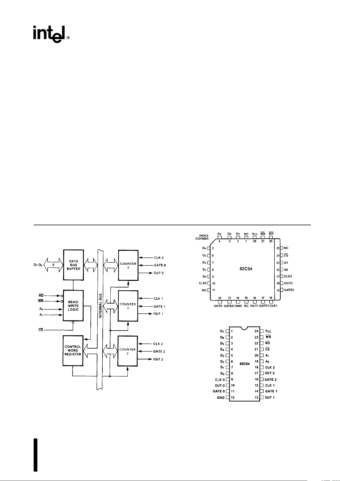
231244–1
Figure 1. 82C54 Block Diagram
231244–3
PLASTIC LEADED CHIP CARRIER
231244–2
Diagrams are for pin reference only.
Package sizes are not to scale.
Figure 2. 82C54 Pinout
Page 2
82C54
Table 1. Pin Description
Symbol
Pin Number
Type Function
DIP PLCC
D7-D
0
1-8 2-9 I/O Data: Bidirectional tri-state data bus lines,
connected to system data bus.
CLK 0 9 10 I Clock 0: Clock input of Counter 0.
OUT 0 10 12 O Output 0: Output of Counter 0.
GATE 0 11 13 I Gate 0: Gate input of Counter 0.
GND 12 14 Ground: Power supply connection.
OUT 1 13 16 O Out 1: Output of Counter 1.
GATE 1 14 17 I Gate 1: Gate input of Counter 1.
CLK 1 15 18 I Clock 1: Clock input of Counter 1.
GATE 2 16 19 I Gate 2: Gate input of Counter 2.
OUT 2 17 20 O Out 2: Output of Counter 2.
CLK 2 18 21 I Clock 2: Clock input of Counter 2.
A1,A
0
20-19 23-22 I Address: Used to select one of the three Counters
or the Control Word Register for read or write
operations. Normally connected to the system
address bus.
A
1
A
0
Selects
0 0 Counter 0
0 1 Counter 1
1 0 Counter 2
1 1 Control Word Register
CS 21 24 I Chip Select: A low on this input enables the 82C54
to respond to RD
and WR signals. RD and WR are
ignored otherwise.
RD 22 26 I Read Control: This input is low during CPU read
operations.
WR 23 27 I Write Control: This input is low during CPU write
operations.
V
CC
24 28 Power:a5V power supply connection.
NC 1, 11, 15, 25 No Connect
FUNCTIONAL DESCRIPTION
General
The 82C54 is a programmable interval timer/counter
designed for use with Intel microcomputer systems.
It is a general purpose, multi-timing element that can
be treated as an array of I/O ports in the system
software.
The 82C54 solves one of the most common problems in any microcomputer system, the generation
of accurate time delays under software control. Instead of setting up timing loops in software, the programmer configures the 82C54 to match his requirements and programs one of the counters for the de-
sired delay. After the desired delay, the 82C54 will
interrupt the CPU. Software overhead is minimal and
variable length delays can easily be accommodated.
Some of the other counter/timer functions common
to microcomputers which can be implemented with
the 82C54 are:
#
Real time clock
#
Even counter
#
Digital one-shot
#
Programmable rate generator
#
Square wave generator
#
Binary rate multiplier
#
Complex waveform generator
#
Complex motor controller
2
Page 3
82C54
Block Diagram
DATA BUS BUFFER
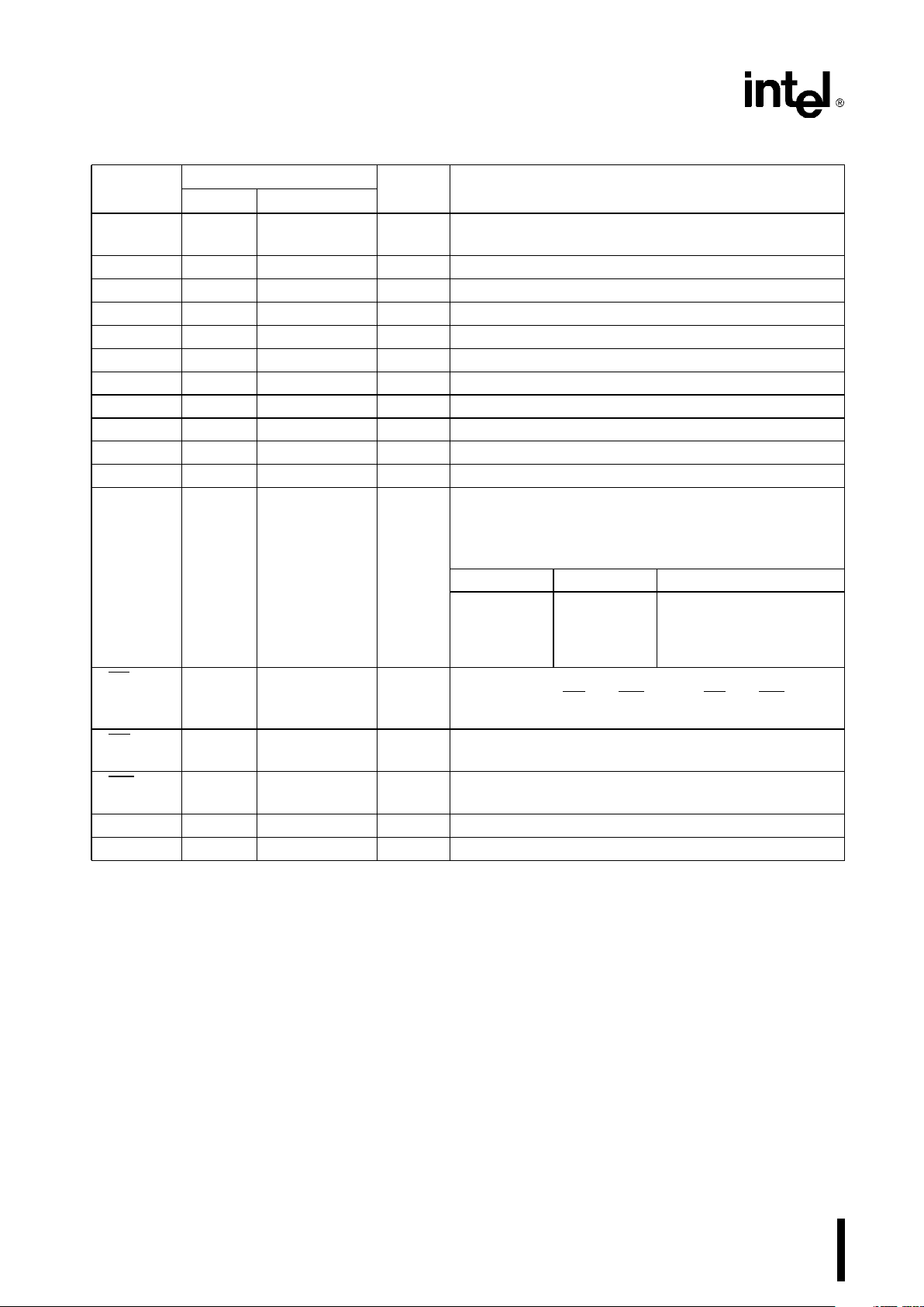
This 3-state, bi-directional, 8-bit buffer is used to interface the 82C54 to the system bus (see Figure 3).
231244–4
Figure 3. Block Diagram Showing Data Bus
Buffer and Read/Write Logic Functions
READ/WRITE LOGIC
The Read/Write Logic accepts inputs from the system bus and generates control signals for the other
functional blocks of the 82C54. A
1
and A0select
one of the three counters or the Control Word Register to be read from/written into. A ‘‘low’’ on the RD
input tells the 82C54 that the CPU is reading one of
the counters. A ‘‘low’’ on the WR
input tells the
82C54 that the CPU is writing either a Control Word
or an initial count. Both RD
and WR are qualified by
CS
;RDand WR are ignored unless the 82C54 has
been selected by holding CS
low.
The WR
Ý
and CLK signals should be synchronous.
This is accomplished by using a CLK input signal to
the 82C54 counters which is a derivative of the system clock source. Another technique is to externally
synchronize the WRÝand CLK input signals. This is
done by gating WR
Ý
with CLK.
CONTROL WORD REGISTER
The Control Word Register (see Figure 4) is selected
by the Read/Write Logic when A
1,A0
e
11. If the
CPU then does a write operation to the 82C54, the
data is stored in the Control Word Register and is
interpreted as a Control Word used to define the
operation of the Counters.
The Control Word Register can only be written to;
status information is available with the Read-Back
Command.
231244–5
Figure 4. Block Diagram Showing Control Word
Register and Counter Functions
COUNTER 0, COUNTER 1, COUNTER 2
These three functional blocks are identical in operation, so only a single Counter will be described. The
internal block diagram of a single counter is shown
in Figure 5.
The Counters are fully independent. Each Counter
may operate in a different Mode.
The Control Word Register is shown in the figure; it
is not part of the Counter itself, but its contents determine how the Counter operates.
3
Page 4
82C54
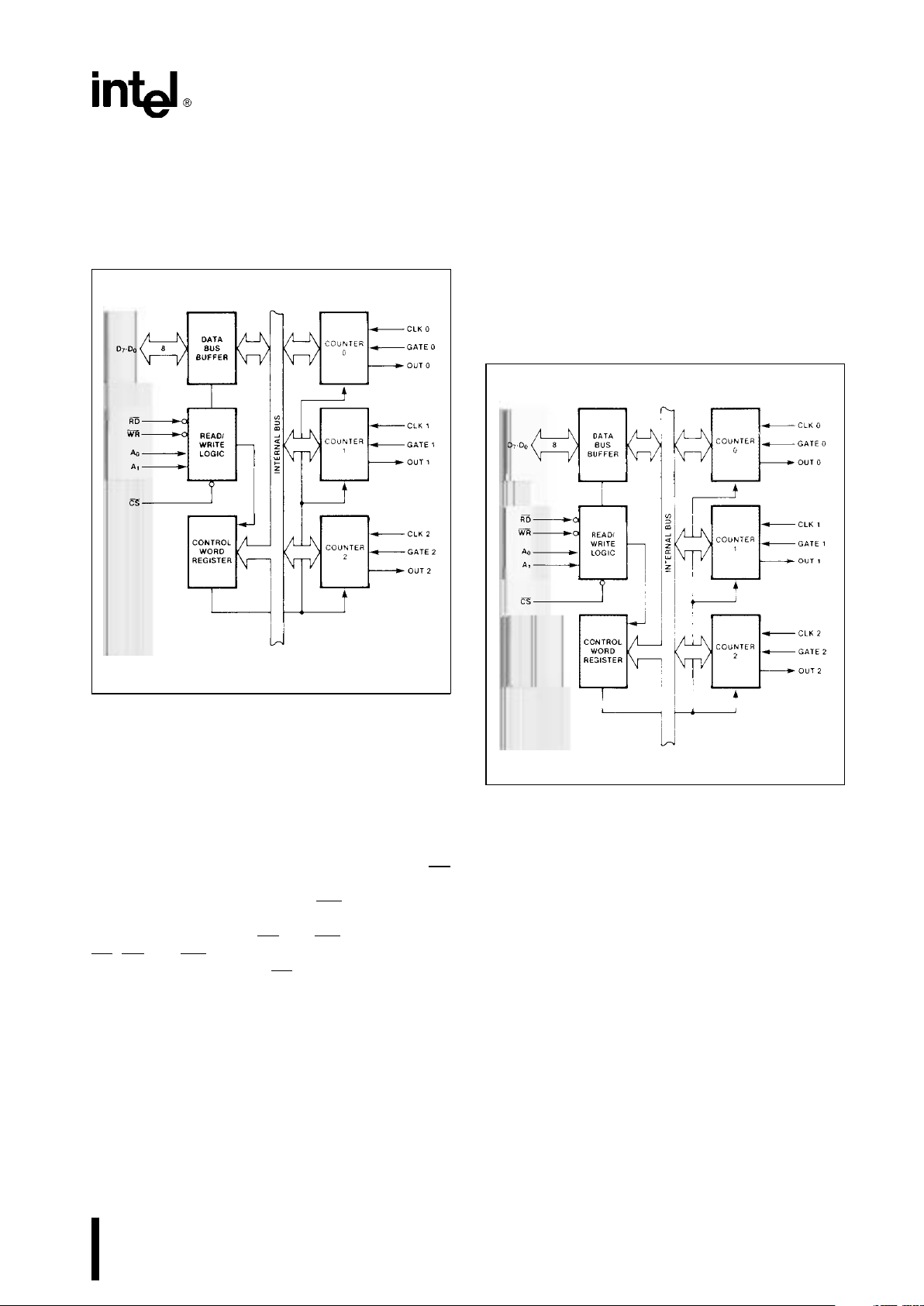
231244–6
Figure 5. Internal Block Diagram of a Counter
The status register, shown in the Figure, when
latched, contains the current contents of the Control
Word Register and status of the output and null
count flag. (See detailed explanation of the ReadBack command.)
The actual counter is labelled CE (for ‘‘Counting Element’’). It is a 16-bit presettable synchronous down
counter.
OL
M
and OLLare two 8-bit latches. OL stands for
‘‘Output Latch’’; the subscripts M and L stand for
‘‘Most significant byte’’ and ‘‘Least significant byte’’
respectively. Both are normally referred to as one
unit and called just OL. These latches normally ‘‘follow’’ the CE, but if a suitable Counter Latch Command is sent to the 82C54, the latches ‘‘latch’’ the
present count until read by the CPU and then return
to ‘‘following’’ the CE. One latch at a time is enabled
by the counter’s Control Logic to drive the internal
bus. This is how the 16-bit Counter communicates
over the 8-bit internal bus. Note that the CE itself
cannot be read; whenever you read the count, it is
the OL that is being read.
Similarly, there are two 8-bit registers called CR
M
and CRL(for ‘‘Count Register’’). Both are normally
referred to as one unit and called just CR. When a
new count is written to the Counter, the count is
stored in the CR and later transferred to the CE. The
Control Logic allows one register at a time to be
loaded from the internal bus. Both bytes are transferred to the CE simultaneously. CR
M
and CRLare
cleared when the Counter is programmed. In this
way, if the Counter has been programmed for one
byte counts (either most significant byte only or least
significant byte only) the other byte will be zero.
Note that the CE cannot be written into; whenever a
count is written, it is written into the CR.
The Control Logic is also shown in the diagram. CLK
n, GATE n, and OUT n are all connected to the outside world through the Control Logic.
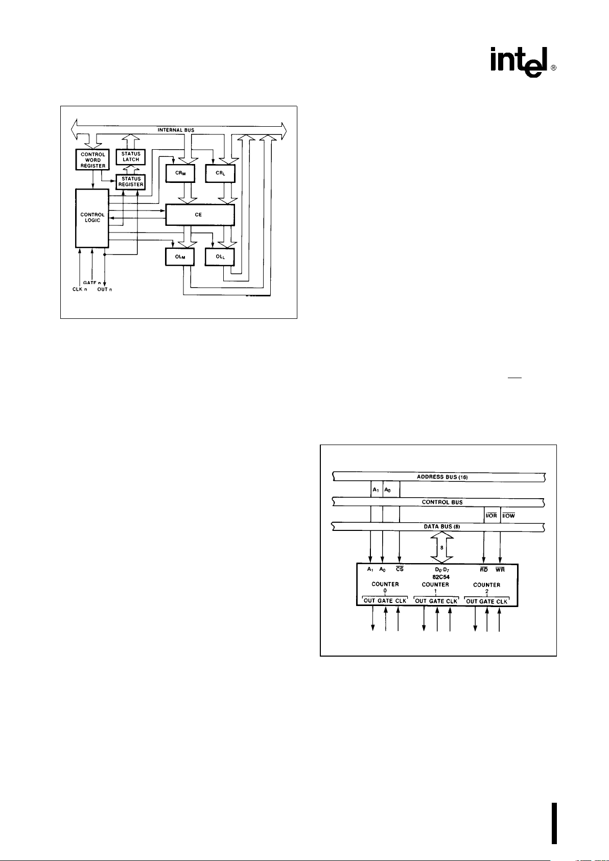
82C54 SYSTEM INTERFACE
The 82C54 is treated by the systems software as an
array of peripheral I/O ports; three are counters and
the fourth is a control register for MODE programming.
Basically, the select inputs A
0,A1
connect to the A0,
A
1
address bus signals of the CPU. The CS can be
derived directly from the address bus using a linear
select method. Or it can be connected to the output
of a decoder, such as an Intel 8205 for larger systems.
231244–7
Figure 6. 82C54 System Interface
4
Page 5
82C54
OPERATIONAL DESCRIPTION
General
After power-up, the state of the 82C54 is undefined.
The Mode, count value, and output of all Counters
are undefined.
How each Counter operates is determined when it is
programmed. Each Counter must be programmed
before it can be used. Unused counters need not be
programmed.
Programming the 82C54
Counters are programmed by writing a Control Word
and then an initial count. The control word format is
shown in Figure 7.
All Control Words are written into the Control Word
Register, which is selected when A
1,A0
e
11. The
Control Word itself specifies which Counter is being
programmed.
By contrast, initial counts are written into the Counters, not the Control Word Register. The A
1,A0
inputs are used to select the Counter to be written
into. The format of the initial count is determined by
the Control Word used.
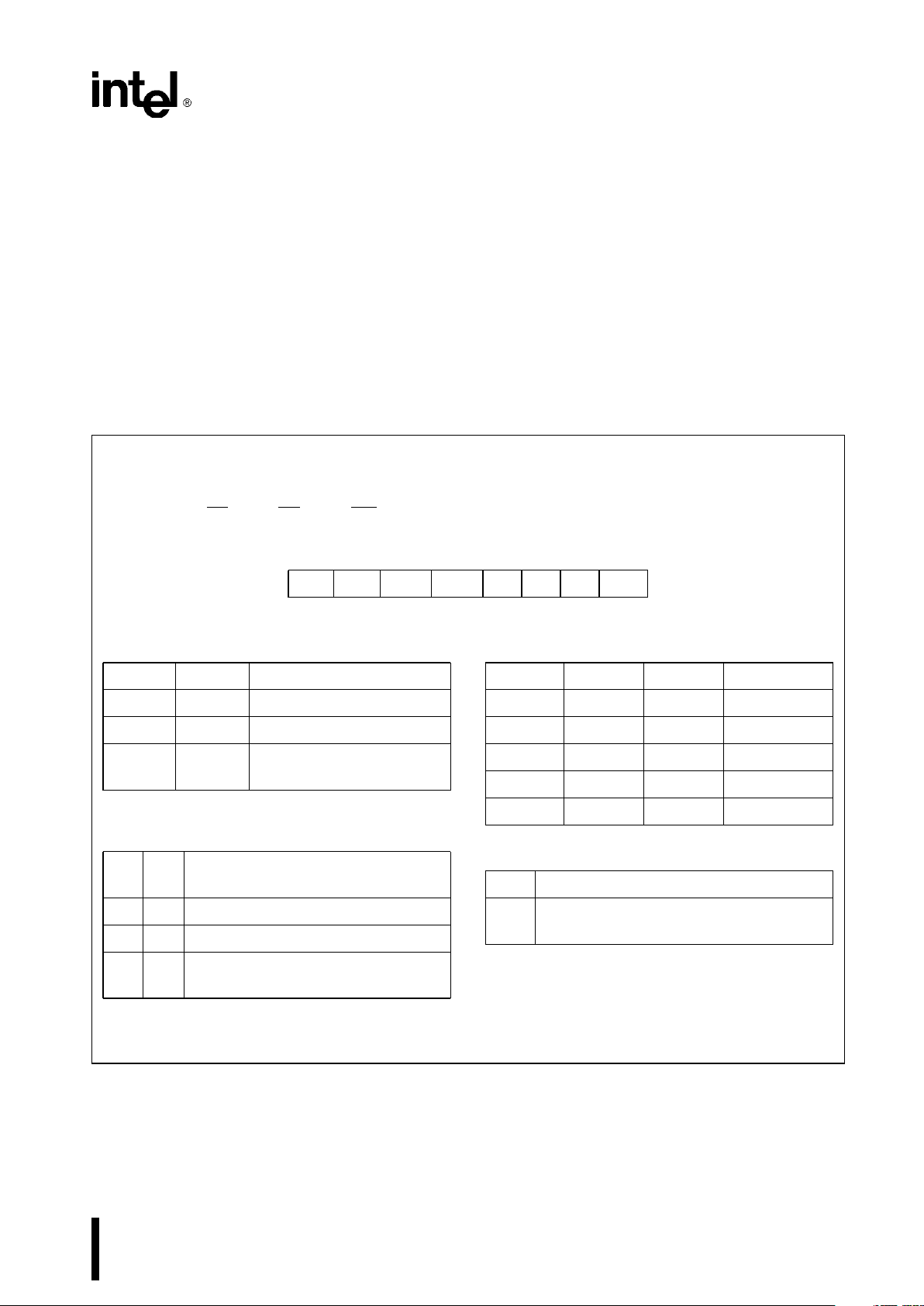
Control Word Format
A1,A
0
e
11 CSe0RDe1WRe0
D
7D6D5D4D3D2D1D0
SC1 SC0 RW1 RW0 M2 M1 M0 BCD
SC Ð Select Counter:
SC1 SC0
0 0 Select Counter 0
0 1 Select Counter 1
1 0 Select Counter 2
11
Read-Back Command
(See Read Operations)
RW Ð Read/Write:
RW1 RW0
0 0 Counter Latch Command (see Read
Operations)
0 1 Read/Write least significant byte only.
1 0 Read/Write most significant byte only.
1 1 Read/Write least significant byte first,
then most significant byte.
NOTE: Don’t care bits (X) should be 0 to insure
compatibility with future Intel products.
M Ð MODE:
M2 M1 M0
0 0 0 Mode 0
0 0 1 Mode 1
X 1 0 Mode 2
X 1 1 Mode 3
1 0 0 Mode 4
1 0 1 Mode 5
BCD:
0 Binary Counter 16-bits
1 Binary Coded Decimal (BCD) Counter
(4 Decades)
Figure 7. Control Word Format
5
Page 6

82C54
Write Operations
The programming procedure for the 82C54 is very
flexible. Only two conventions need to be remembered:
1) For each Counter, the Control Word must be
written before the initial count is written.
2) The initial count must follow the count format
specified in the Control Word (least significant
byte only, most significant byte only, or least significant byte and then most significant byte).
Since the Control Word Register and the three
Counters have separate addresses (selected by the
A
1,A0
inputs), and each Control Word specifies the
Counter it applies to (SC0, SC1 bits), no special in-
struction sequence is required. Any programming
sequence that follows the conventions above is acceptable.
A new initial count may be written to a Counter at
any time without affecting the Counter’s programmed Mode in any way. Counting will be affected
as described in the Mode definitions. The new count
must follow the programmed count format.
If a Counter is programmed to read/write two-byte
counts, the following precaution applies: A program
must not transfer control between writing the first
and second byte to another routine which also writes
into that same Counter. Otherwise, the Counter will
be loaded with an incorrect count.
A
1
A
0
Control Word Ð Counter 0 1 1
LSB of count Ð Counter 0 0 0
MSB of count Ð Counter 0 0 0
Control Word Ð Counter 1 1 1
LSB of count Ð Counter 1 0 1
MSB of count Ð Counter 1 0 1
Control Word Ð Counter 2 1 1
LSB of count Ð Counter 2 1 0
MSB of count Ð Counter 2 1 0
A
1
A
0
Control Word Ð Counter 0 1 1
Counter Word Ð Counter 1 1 1
Control Word Ð Counter 2 1 1
LSB of count Ð Counter 2 1 0
LSB of count Ð Counter 1 0 1
LSB of count Ð Counter 0 0 0
MSB of count Ð Counter 0 0 0
MSB of count Ð Counter 1 0 1
MSB of count Ð Counter 2 1 0
A
1
A
0
Control Word Ð Counter 2 1 1
Control Word Ð Counter 1 1 1
Control Word Ð Counter 0 1 1
LSB of count Ð Counter 2 1 0
MSB of count Ð Counter 2 1 0
LSB of count Ð Counter 1 0 1
MSB of count Ð Counter 1 0 1
LSB of count Ð Counter 0 0 0
MSB of count Ð Counter 0 0 0
A
1
A
0
Control Word Ð Counter 1 1 1
Control Word Ð Counter 0 1 1
LSB of count Ð Counter 1 0 1
Control Word Ð Counter 2 1 1
LSB of count Ð Counter 0 0 0
MSB of count Ð Counter 1 0 1
LSB of count Ð Counter 2 1 0
MSB of count Ð Counter 0 0 0
MSB of count Ð Counter 2 1 0
NOTE:
In all four examples, all counters are programmed to read/write two-byte counts.
These are only four of many possible programming sequences.
Figure 8. A Few Possible Programming Sequences
Read Operations
It is often desirable to read the value of a Counter
without disturbing the count in progress. This is easily done in the 82C54.
There are three possible methods for reading the
counters: a simple read operation, the Counter
Latch Command, and the Read-Back Command.
Each is explained below. The first method is to perform a simple read operation. To read the Counter,
which is selected with the A1, A0 inputs, the CLK
input of the selected Counter must be inhibited by
using either the GATE input or external logic. Otherwise, the count may be in the process of changing
when it is read, giving an undefined result.
6
Page 7

82C54
COUNTER LATCH COMMAND
The second method uses the ‘‘Counter Latch Command’’. Like a Control Word, this command is written
to the Control Word Register, which is selected
when A
1,A0
e
11. Also like a Control Word, the
SC0, SC1 bits select one of the three Counters, but
two other bits, D5 and D4, distinguish this command
from a Control Word.
A1,A
0
e
11; CSe0; RDe1; WRe0
D
7
D
6
D5D4D3D2D1D
0
SC1 SC0 0 0 X X X X
SC1, SC0 - specify counter to be latched
SC1 SC0 Counter
00 0
01 1
10 2
1 1 Read-Back Command
D5,D4 - 00 designates Counter Latch Command
X - don’t care
NOTE:
Don’t care bits (X) should be 0 to insure compatibility
with future Intel products.
Figure 9. Counter Latching Command Format
The selected Counter’s output latch (OL) latches the
count at the time the Counter Latch Command is
received. This count is held in the latch until it is read
by the CPU (or until the Counter is reprogrammed).
The count is then unlatched automatically and the
OL returns to ‘‘following’’ the counting element (CE).
This allows reading the contents of the Counters
‘‘on the fly’’ without affecting counting in progress.
Multiple Counter Latch Commands may be used to
latch more than one Counter. Each latched Counter’s OL holds its count until it is read. Counter Latch
Commands do not affect the programmed Mode of
the Counter in any way.
If a Counter is latched and then, some time later,
latched again before the count is read, the second
Counter Latch Command is ignored. The count read
will be the count at the time the first Counter Latch
Command was issued.
With either method, the count must be read according to the programmed format; specifically, if the
Counter is programmed for two byte counts, two
bytes must be read. The two bytes do not have to be
read one right after the other; read or write or pro-
gramming operations of other Counters may be inserted between them.
Another feature of the 82C54 is that reads and
writes of the same Counter may be interleaved; for
example, if the Counter is programmed for two byte
counts, the following sequence is valid.
1. Read least significant byte.
2. Write new least significant byte.
3. Read most significant byte.
4. Write new most significant byte.
If a Counter is programmed to read/write two-byte
counts, the following precaution applies; A program
must not transfer control between reading the first
and second byte to another routine which also reads
from that same Counter. Otherwise, an incorrect
count will be read.
READ-BACK COMMAND
The third method uses the Read-Back command.
This command allows the user to check the count
value, programmed Mode, and current state of the
OUT pin and Null Count flag of the selected counter(s).
The command is written into the Control Word Register and has the format shown in Figure 10. The
command applies to the counters selected by setting their corresponding bits D3,D2,D1
e
1.
A0, A1e11 CSe0RDe1WRe0
D
7D6D5
D4D3D2D1D
0
1 1 COUNT STATUS CNT 2 CNT 1 CNT 0 0
D5:0eLatch count of selected counter(s)
D4:0eLatch status of selected counter(s)
D
3
:1eSelect counter 2
D
2
:1eSelect counter 1
D
1
:1eSelect counter 0
D
0
: Reserved for future expansion; must be 0
Figure 10. Read-Back Command Format
The read-back command may be used to latch multiple counter output latches (OL) by setting the
COUNT
bit D5e0 and selecting the desired counter(s). This single command is functionally equivalent to several counter latch commands, one for
each counter latched. Each counter’s latched count
is held until it is read (or the counter is reprogrammed). That counter is automatically unlatched
when read, but other counters remain latched until
they are read. If multiple count read-back commands
are issued to the same counter without reading the
7
Page 8

82C54
count, all but the first are ignored; i.e., the count
which will be read is the count at the time the first
read-back command was issued.
The read-back command may also be used to latch
status information of selected counter(s) by setting
STATUS
bit D4e0. Status must be latched to be
read; status of a counter is accessed by a read from
that counter.
The counter status format is shown in Figure 11. Bits
D5 through D0 contain the counter’s programmed
Mode exactly as written in the last Mode Control
Word. OUTPUT bit D7 contains the current state of
the OUT pin. This allows the user to monitor the
counter’s output via software, possibly eliminating
some hardware from a system.
D
7
D
6
D5D4D3D2D1D
0
OUTPUT
NULL
RW1 RW0 M2 M1 M0 BCD
COUNT
D71eOut Pin is 1
0
e
Out Pin is 0
D61eNull count
0
e
Count available for reading
D
5-D0
Counter Programmed Mode (See Figure 7)
Figure 11. Status Byte
NULL COUNT bit D6 indicates when the last count
written to the counter register (CR) has been loaded
into the counting element (CE). The exact time this
happens depends on the Mode of the counter and is
described in the Mode Definitions, but until the count
is loaded into the counting element (CE), it can’t be
read from the counter. If the count is latched or read
before this time, the count value will not reflect the
new count just written. The operation of Null Count
is shown in Figure 12.
THIS ACTION: CAUSES:
A. Write to the control
Null count
e
1
word register:
[1]
B. Write to the count
Null count
e
1
register (CR);
[2]
C. New count is loaded
Null count
e
0
into CE (CRxCE);
[1]
Only the counter specified by the control word will
have its null count set to 1. Null count bits of other
counters are unaffected.
[2]
If the counter is programmed for two-byte counts
(least significant byte then most significant byte) null
count goes to 1 when the second byte is written.
Figure 12. Null Count Operation
If multiple status latch operations of the counter(s)
are performed without reading the status, all but the
first are ignored; i.e., the status that will be read is
the status of the counter at the time the first status
read-back command was issued.
Both count and status of the selected counter(s)
may be latched simultaneously by setting both
COUNT
and STATUS bits D5,D4e0. This is functionally the same as issuing two separate read-back
commands at once, and the above discussions apply here also. Specifically, if multiple count and/or
status read-back commands are issued to the same
counter(s) without any intervening reads, all but the
first are ignored. This is illustrated in Figure 13.
If both count and status of a counter are latched, the
first read operation of that counter will return latched
status, regardless of which was latched first. The
next one or two reads (depending on whether the
counter is programmed for one or two type counts)
return latched count. Subsequent reads return unlatched count.
Command
Description Results
D
7D6D5D4D3D2D1D0
11000010Read back count and status of Count and status latched
Counter 0 for Counter 0
11100100Read back status of Counter 1 Status latched for Counter 1
11101100Read back status of Counters 2, 1 Status latched for Counter
2, but not Counter 1
11011000Read back count of Counter 2 Count latched for Counter 2
11000100Read back count and status of Count latched for Counter 1,
Counter 1 but not status
11100010Read back status of Counter 1 Command ignored, status
already latched for Counter 1
Figure 13. Read-Back Command Example
8
Page 9

82C54
CS RD WR A1A
0
0 1 0 0 0 Write into Counter 0
0 1 0 0 1 Write into Counter 1
0 1 0 1 0 Write into Counter 2
0 1 0 1 1 Write Control Word
0 0 1 0 0 Read from Counter 0
0 0 1 0 1 Read from Counter 1
0 0 1 1 0 Read from Counter 2
0 0 1 1 1 No-Operation (3-State)
1 X X X X No-Operation (3-State)
0 1 1 X X No-Operation (3-State)
Figure 14. Read/Write Operations Summary
Mode Definitions
The following are defined for use in describing the
operation of the 82C54.
CLK PULSE: a rising edge, then a falling edge, in
that order, of a Counter’s CLK input.
TRIGGER: a rising edge of a Counter’s GATE in-
put.
COUNTER LOADING: the transfer of a count from
the CR to the CE (refer to
the ‘‘Functional Description’’)
MODE 0: INTERRUPT ON TERMINAL COUNT
Mode 0 is typically used for event counting. After the
Control Word is written, OUT is initially low, and will
remain low until the Counter reaches zero. OUT then
goes high and remains high until a new count or a
new Mode 0 Control Word is written into the Counter.
GATE
e
1 enables counting; GATEe0 disables
counting. GATE has no effect on OUT.
After the Control Word and initial count are written to
a Counter, the initial count will be loaded on the next
CLK pulse. This CLK pulse does not decrement the
count, so for an initial count of N, OUT does not go
high until N
a
1 CLK pulses after the initial count is
written.
If a new count is written to the Counter, it will be
loaded on the next CLK pulse and counting will continue from the new count. If a two-byte count is written, the following happens:
1) Writing the first byte does not disable counting.
OUT is set low immediately (no clock pulse required).
2) Writing the second byte allows the new count to
be loaded on the next CLK pulse.
3) When there is a count in progress, writing a new
LSB before the counter has counted down to 0
and rolled over to FFFFh, WILL stop the counter.
However, if the LSB is loaded AFTER the counter
has rolled over to FFFFh, so that an MSB now
exists in the counter, then the counter WILL NOT
stop.
This allows the counting sequence to be synchronized by software. Again, OUT does not go high until N
a
1 CLK pulses after the new count of N is written.
9
Page 10

82C54
If an initial count is written while GATEe0, it will
still be loaded on the next CLK pulse. When GATE
goes high, OUT will go high N CLK pulses later; no
CLK pulse is needed to load the Counter as this has
already been done.
231244–8
NOTE:
The Following Conventions Apply To All Mode Timing
Diagrams:
1. Counters are programmed for binary (not BCD)
counting and for Reading/Writing least significant byte
(LSB) only.
2. The counter is always selected (CS
always low).
3. CW stands for ‘‘Control Word’’; CW
e
10 means a
control word of 10, hex is written to the counter.
4. LSB stands for ‘‘Least Significant Byte’’ of count.
5. Numbers below diagrams are count values.
The lower number is the least significant byte.
The upper number is the most significant byte. Since
the counter is programmed to Read/Write LSB only,
the most significant byte cannot be read.
N stands for an undefined count.
Vertical lines show transitions between count values.
Figure 15. Mode 0
MODE 1: HARDWARE RETRIGGERABLE
ONE-SHOT
OUT will be initially high. OUT will go low on the CLK
pulse following a trigger to begin the one-shot pulse,
and will remain low until the Counter reaches zero.
OUT will then go high and remain high until the CLK
pulse after the next trigger.
After writing the Control Word and initial count, the
Counter is armed. A trigger results in loading the
Counter and setting OUT low on the next CLK pulse,
thus starting the one-shot pulse. An initial count of N
will result in a one-shot pulse N CLK cycles in duration. The one-shot is retriggerable, hence OUT will
remain low for N CLK pulses after any trigger. The
one-shot pulse can be repeated without rewriting the
same count into the counter. GATE has no effect on
OUT.
If a new count is written to the Counter during a oneshot pulse, the current one-shot is not affected unless the Counter is retriggered. In that case, the
Counter is loaded with the new count and the oneshot pulse continues until the new count expires.
231244–9
Figure 16. Mode 1
10
Page 11

82C54
MODE 2: RATE GENERATOR
This Mode functions like a divide-by-N counter. It is
typicially used to generate a Real Time Clock interrupt. OUT will initially be high. When the initial count
has decremented to 1, OUT goes low for one CLK
pulse. OUT then goes high again, the Counter reloads the initial count and the process is repeated.
Mode 2 is periodic; the same sequence is repeated
indefinitely. For an initial count of N, the sequence
repeats every N CLK cycles.
GATE
e
1 enables counting; GATEe0 disables
counting. If GATE goes low during an output pulse,
OUT is set high immediately. A trigger reloads the
Counter with the initial count on the next CLK pulse;
OUT goes low N CLK pulses after the trigger. Thus
the GATE input can be used to synchronize the
Counter.
After writing a Control Word and initial count, the
Counter will be loaded on the next CLK pulse. OUT
goes low N CLK Pulses after the initial count is written. This allows the Counter to be synchronized by
software also.
231244–10
NOTE:
A GATE transition should not occur one clock prior to
terminal count.
Figure 17. Mode 2
Writing a new count while counting does not affect
the current counting sequence. If a trigger is received after writing a new count but before the end
of the current period, the Counter will be loaded with
the new count on the next CLK pulse and counting
will continue from the new count. Otherwise, the
new count will be loaded at the end of the current
counting cycle. In mode 2, a COUNT of 1 is illegal.
MODE 3: SQUARE WAVE MODE
Mode 3 is typically used for Baud rate generation.
Mode 3 is similar to Mode 2 except for the duty cycle
of OUT. OUT will initially be high. When half the initial count has expired, OUT goes low for the remainder of the count. Mode 3 is periodic; the sequence
above is repeated indefinitely. An initial count of N
results in a square wave with a period of N CLK
cycles.
GATE
e
1 enables counting; GATEe0 disables
counting. If GATE goes low while OUT is low, OUT is
set high immediately; no CLK pulse is required. A
trigger reloads the Counter with the initial count on
the next CLK pulse. Thus the GATE input can be
used to synchronize the Counter.
After writing a Control Word and initial count, the
Counter will be loaded on the next CLK pulse. This
allows the Counter to be synchronized by software
also.
Writing a new count while counting does not affect
the current counting sequence. If a trigger is received after writing a new count but before the end
of the current half-cycle of the square wave, the
Counter will be loaded with the new count on the
next CLK pulse and counting will continue from the
new count. Otherwise, the new count will be loaded
at the end of the current half-cycle.
Mode 3 is implemented as follows:
Even counts: OUT is initially high. The initial count is
loaded on one CLK pulse and then is decremented
by two on succeeding CLK pulses. When the count
expires OUT changes value and the Counter is reloaded with the initial count. The above process is
repeated indefinitely.
Odd counts: OUT is initially high. The initial count
minus one (an even number) is loaded on one CLK
pulse and then is decremented by two on succeeding CLK pulses. One CLK pulse
after
the count expires, OUT goes low and the Counter is reloaded
with the initial count minus one. Succeeding CLK
pulses decrement the count by two. When the count
expires, OUT goes high again and the Counter is
reloaded with the initial count minus one. The above
process is repeated indefinitely. So for odd counts,
11
Page 12

82C54
OUT will be high for (Na1)/2 counts and low for
(N
b
1)/2 counts.
231244–11
NOTE:
A GATE transition should not occur one clock prior to
terminal count.
Figure 18. Mode 3
MODE 4: SOFTWARE TRIGGERED STROBE
OUT will be initially high. When the initial count expires, OUT will go low for one CLK pulse and then
go high again. The counting sequence is ‘‘triggered’’
by writing the initial count.
GATE
e
1 enables counting; GATEe0 disables
counting. GATE has no effect on OUT.
After writing a Control Word and initial count, the
Counter will be loaded on the next CLK pulse. This
CLK pulse does not decrement the count, so for an
initial count of N, OUT does not strobe low until
N
a
1 CLK pulses after the initial count is written.
If a new count is written during counting, it will be
loaded on the next CLK pulse and counting will continue from the new count. If a two-byte count is written, the following happens:
1) Writing the first byte has no effect on counting.
2) Writing the second byte allows the new count to
be loaded on the next CLK pulse.
This allows the sequence to be ‘‘retriggered’’ by
software. OUT strobes low N
a
1 CLK pulses after
the new count of N is written.
231244–12
Figure 19. Mode 4
MODE 5: HARDWARE TRIGGERED STROBE
(RETRIGGERABLE)
OUT will initially be high. Counting is triggered by a
rising edge of GATE. When the initial count has expired, OUT will go low for one CLK pulse and then
go high again.
12
Page 13

82C54
After writing the Control Word and initial count, the
counter will not be loaded until the CLK pulse after a
trigger. This CLK pulse does not decrement the
count, so for an initial count of N, OUT does not
strobe low until N
a
1 CLK pulses after a trigger.
A trigger results in the Counter being loaded with the
initial count on the next CLK pulse. The counting
sequence is retriggerable. OUT will not strobe low
for N
a
1 CLK pulses after any trigger. GATE has
no effect on OUT.
If a new count is written during counting, the current
counting sequence will not be affected. If a trigger
occurs after the new count is written but before the
current count expires, the Counter will be loaded
with the new count on the next CLK pulse and
counting will continue from there.
231244–13
Figure 20. Mode 5
Signal Low
Status Or Going Rising High
Modes Low
0 Disables Ð Enables
counting counting
1 Ð 1) Initiates Ð
counting
2) Resets output
after next
clock
2 1) Disables
counting Initiates Enables
2) Sets output counting counting
immediately
high
3 1) Disables
counting Initiates Enables
2) Sets output counting counting
immediately
high
4 Disables Ð Enables
counting counting
5 Ð Initiates Ð
counting
Figure 21. Gate Pin Operations Summary
MODE
MIN MAX
COUNT COUNT
01 0
11 0
22 0
32 0
41 0
NOTE:
0 is equivalent to 2
16
for binary counting and 104for
BCD counting
Figure 22. Minimum and Maximum initial Counts
13
Page 14

82C54
Operation Common to All Modes
Programming
When a Control Word is written to a Counter, all
Control Logic is immediately reset and OUT goes to
a known initial state; no CLK pulses are required for
this.
GATE
The GATE input is always sampled on the rising
edge of CLK. In Modes 0, 2, 3, and 4 the GATE input
is level sensitive, and the logic level is sampled on
the rising edge of CLK. In Modes 1, 2, 3, and 5 the
GATE input is rising-edge sensitive. In these Modes,
a rising edge of GATE (trigger) sets an edge-sensitive flip-flop in the Counter. This flip-flop is then sampled on the next rising edge of CLK; the flip-flop is
reset immediately after it is sampled. In this way, a
trigger will be detected no matter when it occursÐa
high logic level does not have to be maintained until
the next rising edge of CLK. Note that in Modes 2
and 3, the GATE input is both edge- and level-sensitive. In Modes 2 and 3, if a CLK source other than
the system clock is used, GATE should be pulsed
immediately following WR of a new count value.
COUNTER
New counts are loaded and Counters are decremented on the falling edge of CLK.
The largest possible initial count is 0; this is equivalent to 2
16
for binary counting and 104for BCD
counting.
The Counter does not stop when it reaches zero. In
Modes 0, 1, 4, and 5 the Counter ‘‘wraps around’’ to
the highest count, either FFFF hex for binary counting or 9999 for BCD counting, and continues counting. Modes 2 and 3 are periodic; the Counter reloads
itself with the initial count and continues counting
from there.
14
Page 15

82C54
ABSOLUTE MAXIMUM RATINGS*
Ambient Temperature Under Bias.АААААА0§Cto70§C
Storage Temperature АААААААААААА
b
65§toa150§C
Supply Voltage ААААААААААААААААААА
b
0.5 toa8.0V
Operating Voltage АААААААААААААААААА
a
4V toa7V
Voltage on any InputААААААААААGND
b
2V toa6.5V
Voltage on any Output ÀÀGND
b
0.5V to V
CC
a
0.5V
Power Dissipation АААААААААААААААААААААААА1 Watt
NOTICE: This is a production data sheet. The specifications are subject to change without notice.
*
WARNING: Stressing the device beyond the ‘‘Absolute
Maximum Ratings’’ may cause permanent damage.
These are stress ratings only. Operation beyond the
‘‘Operating Conditions’’ is not recommended and extended exposure beyond the ‘‘Operating Conditions’’
may affect device reliability.
D.C. CHARACTERISTICS
(T
A
e
0§Cto70§C, V
CC
e
5Vg10%, GNDe0V) (T
A
eb
40§Ctoa85§C for Extended Temperature)
Symbol Parameter Min Max Units Test Conditions
V
IL
Input Low Voltage
b
0.5 0.8 V
V
IH
Input High Voltage 2.0 V
CC
a
0.5 V
V
OL
Output Low Voltage 0.4 V I
OL
e
2.5 mA
V
OH
Output High Voltage 3.0 V I
OH
eb
2.5 mA
V
CC
b
0.4 V I
OH
eb
100 mA
I
IL
Input Load Current
g
2.0 mAV
IN
e
VCCto 0V
I
OFL
Output Float Leakage Current
g
10 mAV
OUT
e
VCCto 0.0V
I
CC
VCCSupply Current 20 mA
Clk Freq
e
8MHz 82C54
10MHz 82C54-2
I
CCSB
VCCSupply Current-Standby 10 mA CLK FreqeDC
CS
e
VCC.
All Inputs/Data Bus V
CC
All Outputs Floating
I
CCSB1
VCCSupply Current-Standby 150 mA CLK FreqeDC
CS
e
VCC. All Other Inputs,
I/O Pins
e
V
GND
, Outputs Open
C
IN
Input Capacitance 10 pF f
c
e
1 MHz
C
I/O
I/O Capacitance 20 pF
Unmeasured pins
C
OUT
Output Capacitance 20 pF
returned to GND
(5)
A.C. CHARACTERISTICS
(T
A
e
0§Cto70§C, V
CC
e
5Vg10%, GNDe0V) (T
A
eb
40§Ctoa85§C for Extended Temperature)
BUS PARAMETERS (Note 1)
READ CYCLE
Symbol Parameter
82C54-2
Units
Min Max
t
AR
Address Stable Before RD
v
30 ns
t
SR
CS Stable Before RD
v
0ns
t
RA
Address Hold Time After RD
u
0ns
t
RR
RD Pulse Width 95 ns
t
RD
Data Delay from RD
v
85 ns
t
AD
Data Delay from Address 185 ns
t
DF
RDuto Data Floating 5 65 ns
t
RV
Command Recovery Time 165 ns
NOTE:
1. AC timings measured at V
OH
e
2.0V, V
OL
e
0.8V.
15
Page 16

82C54
A.C. CHARACTERISTICS (Continued)
WRITE CYCLE
Symbol Parameter
82C54-2
Units
Min Max
t
AW
Address Stable Before WR
v
0ns
t
SW
CS Stable Before WR
v
0ns
t
WA
Address Hold Time After WR
u
0ns
t
WW
WR Pulse Width 95 ns
t
DW
Data Setup Time Before WR
u
95 ns
t
WD
Data Hold Time After WR
u
0ns
t
RV
Command Recovery Time 165 ns
CLOCK AND GATE
Symbol Parameter
82C54-2
Units
Min Max
t
CLK
Clock Period 100 DC ns
t
PWH
High Pulse Width 30
(3)
ns
t
PWL
Low Pulse Width 50
(3)
ns
T
R
Clock Rise Time 25 ns
t
F
Clock Fall Time 25 ns
t
GW
Gate Width High 50 ns
t
GL
Gate Width Low 50 ns
t
GS
Gate Setup Time to CLK
u
40 ns
t
GH
Gate Hold Time After CLK
u
50
(2)
ns
T
OD
Output Delay from CLK
v
100 ns
t
ODG
Output Delay from Gate
v
100 ns
t
WC
CLK Delay for Loading
(4)
055ns
t
WG
Gate Delay for Sampling
(4)
b
540 ns
t
WO
OUT Delay from Mode Write 240 ns
t
CL
CLK Set Up for Count Latch
b
40 40 ns
NOTES:
2. In Modes 1 and 5 triggers are sampled on each rising clock edge. A second trigger within 70 ns for the 82C54-2 of the
rising clock edge may not be detected.
3. Low-going glitches that violate t
PWH,tPWL
may cause errors requiring counter reprogramming.
4. Except for Extended Temp., See Extended Temp. A.C. Characteristics below.
5. Sampled not 100% tested. T
A
e
25§C.
6. If CLK present at T
WC
min then Count equals Na2 CLK pulses, TWCmax equals Count Na1 CLK pulse. TWCmin to
T
WC
max, count will be either Na1orNa2 CLK pulses.
7. In Modes 1 and 5, if GATE is present when writing a new Count value, at T
WG
min Counter will not be triggered, at T
WG
max Counter will be triggered.
8. If CLK present when writing a Counter Latch or ReadBack Command, at T
CL
min CLK will be reflected in count value
latched, at T
CL
max CLK will not be reflected in the count value latched. Writing a Counter Latch or ReadBack Command
between T
CL
min and TWLmax will result in a latched count vallue which isgone least significant bit.
EXTENDED TEMPERATURE (T
A
eb
40§Ctoa85§C for Extended Temperature)
Symbol Parameter
82C54-2
Units
Min Max
t
WC
CLK Delay for Loading
b
25 25 ns
t
WG
Gate Delay for Sampling
b
25 25 ns
16
Page 17

82C54
WAVEFORMS
WRITE
231244–14
READ
231244–15
RECOVERY
231244–16
17
Page 18

82C54
CLOCK AND GATE
231244–17
* Last byte of count being written
A.C. TESTING INPUT, OUTPUT WAVEFORM
INPUT/OUTPUT
231244–18
A.C. Testing: Inputs are driven at 2.4V for a logic ‘‘1’’ and 0.45V
for a logic ‘‘0.’’ Timing measurements are made at 2.0V for a logic
‘‘1’’ and 0.8V for a logic ‘‘0.’’
A.C. TESTING LOAD CIRCUIT
231244–19
C
L
e
150 pF
C
L
includes jig capacitance
REVISION SUMMARY
The following list represents the key differences between Rev. 005 and 006 of the 82C54 Data Sheet.
1. References to and specifications for the 8 MHz
82C54 are removed. Only the 10 MHz 82C52-2
remains in production.
18
 Loading...