

Page 1
DATA BULLETIN
MX651
© 1997 MX
•COM Inc. www.mxcom.com Tele: 800 638-5577 910 744-5050 Fax: 910 744-5054 Doc. # 20480137.003
4800 Bethania Station Road, Winston-Salem, NC 27105-1201 USA
All trademarks and service marks are held by their respective companies.
Telephone
Subscriber Pulse Metering &
Anti Fraud Tone Processor
PRELIMINARY INFORMATION
Features Applications
•
Rapid 18kHz tone encoder-decoder can
transfer NRZ data
Tx up to 166bps
Rx up to 62bps
•
12kHz Subscriber Pulse Metering
Detector
•
Meets European 12kHz SPM Frequency
Specifications
•
Payphone Applications
•
Card Operated Telephone Installations
•
Component Adjustable Input Sensitivity
•
Low Power 3.3V/5.0V Operation
Clock Oscillator
and Dividers
Sample
& Hold
Sample
& Hold
Filtering and
Frequency Detection
12kHz Channel
Digital
Amplifier
Modulator
Band Pass
Filter
V
BIAS
XTAL
XTAL
EXT
CLKIN
NRZ
DAT A
TXOUT
RX/TX
AMPOUT
IN
IN
DETECT
12kHz
DETECT
18kHz
V
SS
V
DD
Filtering and
Frequency Detection
18kHz Channel
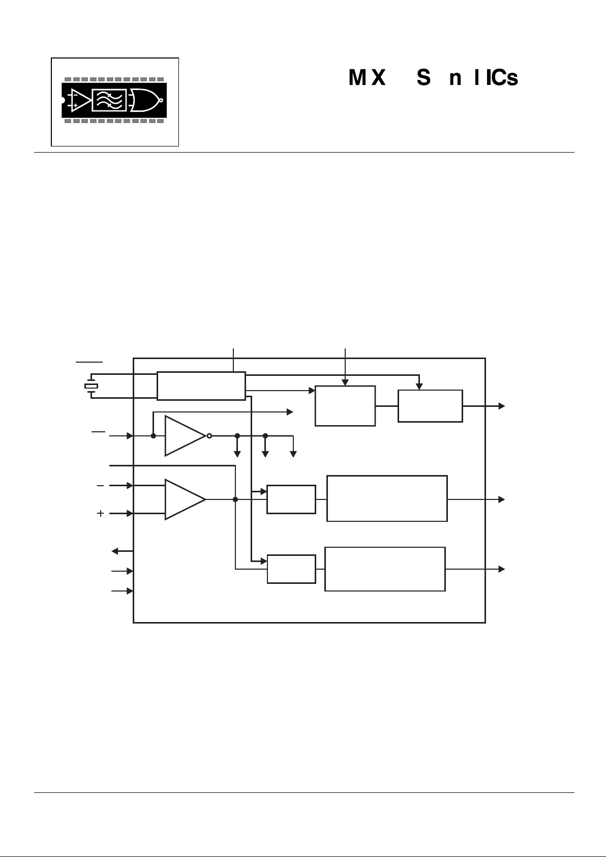
The MX651 is a low power integrated circuit which combines 12kHz Subscriber Pulse Metering (SPM) detection with
18kHz tone processing for anti-fraud purposes within a telephone system. Suitable for battery or line powered systems,
the MX651 is protected from crosstalk and false decoding by employing high accuracy switched capacitor filters. By using
simple logic or µProcessor control the MX651 will:
• Decode 12kHz SPM pulses (in the presence of high level voice and 18kHz signaling) and provide a logic output.
• Transmit an NRZ amplitude modulated 18kHz security tone to line.
• Decode an incoming modulated 18kHz security tone (in the presence of high level voice and 12 kHz SPM tones)
and provide a logic output.
The MX651 is available in a 16-pin SOIC (MX651DW) and a 16-pin PDIP (MX651P) package.
Page 2

Telephone SPM and Anti Fraud Tone Processor 2 MX651 - PRELIMINARY INFORMATION
© 1997 MX•COM Inc. www.mxcom.com Tele: 800 638-5577 910 744-5050 Fax: 910 744-5054 Doc. # 20480137.003
4800 Bethania Station Road, Winston-Salem, NC 27105-1201 USA
All trademarks and service marks are held by their respective companies.
CONTENTS
Section............................................................................................................................................... Page
1. Block Diagram.................................................................................................................................. 3
2. Signal List......................................................................................................................................... 4
3. External Components...................................................................................................................... 5
4. General Description......................................................................................................................... 6
4.1 Overall Function........................................................................................................................................ 6
4.1.1 SPM (12kHz) Detector.......................................................................................................................................6
4.1.2 Security Tone (18kHz) Detector (Rx Mode Only) ..............................................................................................6
4.1.3 Security Tone Transmission (Tx Mode Only).....................................................................................................6
4.2 Description of Blocks (Reference Figure 1) ............................................................................................ 6
4.2.1 Input Amplifier....................................................................................................................................................6
4.2.2 Sample and Hold (12kHz Channel) ...................................................................................................................6
4.2.3 Filtering and Frequency Detection (12kHz Channel).........................................................................................6
4.2.4 Sample and Hold (18kHz Channel) ...................................................................................................................6
4.2.5 Filtering and Frequency Detection (18kHz Channel).........................................................................................6
4.2.6 Clock Oscillator and Dividers.............................................................................................................................7
4.2.7 (Gate ON-OFF) (Tx Only)..................................................................................................................................7
4.2.8 Band Pass Filter (Tx Only).................................................................................................................................7
5. Application ....................................................................................................................................... 7
5.1 Device Sensitivity versus VDD - Input Amplifier Gain................................................................................ 7
5.2 Alias Responses - False Decodes............................................................................................................7
5.2.1 12kHz Channel ..................................................................................................................................................7
5.2.2 18kHz Channel ..................................................................................................................................................8
6. Performance Specifications............................................................................................................ 8
6.1 Electrical Performance..............................................................................................................................8
6.2 System Timing ......................................................................................................................................... 11
6.2.1 Timing Diagrams ...............................................................................................................................................11
6.3 Packaging ................................................................................................................................................ 12
MX•COM, Inc. reserves the right to change specifications at any time and without notice.
Page 3
Telephone SPM and Anti Fraud Tone Processor 3 MX651 - PRELIMINARY INFORMATION
© 1997 MX•COM Inc. www.mxcom.com Tele: 800 638-5577 910 744-5050 Fax: 910 744-5054 Doc. # 20480137.003
4800 Bethania Station Road, Winston-Salem, NC 27105-1201 USA
All trademarks and service marks are held by their respective companies.
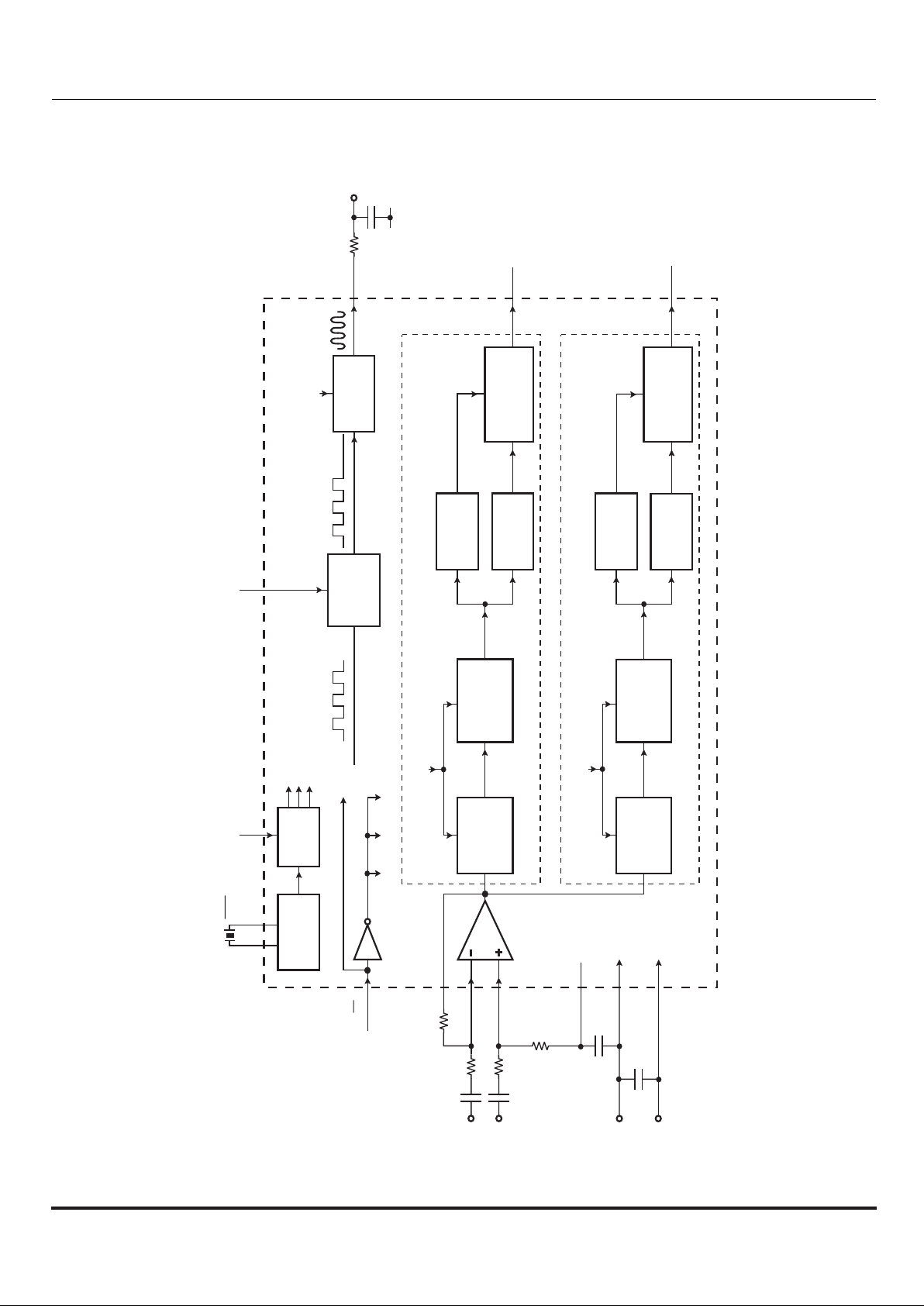
1. Block Diagram
OSCILLATOR
CLOCK
DIVIDERS
71.591kHz
357.955kHz
17.898kHz
17.898kHz
Modulated on/off
LEVEL
DETECTOR
ZERO
CROSSING
DETECTOR
SAMPLE
AND HOLD
HIGH PASS
FILTER 2
fc = 16kHz
71.591kHz
FREQUENCY
MEASUREMENT
Enable
FREQUENCY
MEASUREMENT
Enable
BAND PASS
FILTER
fc = 18kHz
Gate
357.955kHz
V
DD
V
SS
V
SS
RX/TX
POSIN
NEGIN
AMPOUT
NRZ DATA
3.579545MHz Xtal
CLKIN
XT AL XT AL
Powersave 18kHz Channel
PowersaveTx Circuitry
18kHz Channel
12kHz Channel
17.898kHz
SAMPLE
AND HOLD
HIGH PASS
FILTER 1
fc = 5kHz
LEVEL
DETECTOR
ZERO
CROSSING
DETECTOR
17.898kHz
DIGITAL
AMPLITUDE
MODULATOR
V
BIAS
TXOUT (18kHz ASK Signal)
DETECT 18kHz
V
DD
R1
R3
R5
R4
C4
C3
C1
C2
C5
R2
V
SS
DETECT 12kHz
Figure 1: Block Diagram
Page 4

Telephone SPM and Anti Fraud Tone Processor 4 MX651 - PRELIMINARY INFORMATION
© 1997 MX•COM Inc. www.mxcom.com Tele: 800 638-5577 910 744-5050 Fax: 910 744-5054 Doc. # 20480137.003
4800 Bethania Station Road, Winston-Salem, NC 27105-1201 USA
All trademarks and service marks are held by their respective companies.
2. Signal List
Pin No. Signal Type Description
1 XTAL input Input to the on-chip oscillator inverter.
2
XTAL
output Inverted output of the on-chip oscillator.
4 CLKIN input A logic input which may be used when an external clock signal is available in
place of a crystal. The external 3.579545MHz signal is applied to this pin and
XTAL is tied to V
DD
. When not used, this pin should be tied to VDD.
5
RX/ TX
input A logic input which controls the operating mode of the device. In Rx, the
device detects the presence of 12kHz and 18kHz tones. In Tx, the18kHz
detect function is disabled and 18kHz is transmitted from the TXOUT pin
modulated ON -OFF by the NRZ Data pin.
6 NRZ DATA input A logic input used in Tx mode to ASK modulate the TXOUT pin. A logic high
corresponds to no tone and logic low corresponds to 18kHz.
7 TXOUT output The Tx mode output. It is ASK modulated by the NRZ data input pin. It
transmits 18kHz or no tone depending upon the state of the NRZ data input
pin. This pin goes to a high impedance state when in Rx mode.
8VSSpower Negative supply.
9V
BIAS
output A bias line for the internal circuitry, held at VDD/2 It also forms the analog
ground for the input differential amplifier. This pin must be bypassed by a
capacitor mounted close to the device pins (see Figure 1).
10 AMPOUT output Output of the input amplifier. External components are used in conjunction
with the amplifier to couple the line signal into the device. Both inputs are
available to allow a differential configuration because a two wire input is
assumed.
11 NEGIN input Inverting input to the input amplifier.
12 POSIN input Non-inverting input to the input amplifier.
13 DETECT 18kHz output Logic output of the 18kHz channel. Logic 0 when a 18kHz tone (within
specified frequency and amplitude limits) has been detected for a minimum
length of time.
14 DETECT 12kHz output Logic output of the 12kHz channel. Logic 0 when a 12kHz tone (within
specified frequency and amplitude limits) has been detected for a minimum
length of time.
16 V
DD
power Positive Supply. Levels and voltages are dependent upon this supply. This
pin should be bypassed to V
SS
by a capacitor (see Figure 1).
3, 15 N/C No internal connection: leave open circuit.
Page 5

Telephone SPM and Anti Fraud Tone Processor 5 MX651 - PRELIMINARY INFORMATION
© 1997 MX•COM Inc. www.mxcom.com Tele: 800 638-5577 910 744-5050 Fax: 910 744-5054 Doc. # 20480137.003
4800 Bethania Station Road, Winston-Salem, NC 27105-1201 USA
All trademarks and service marks are held by their respective companies.
3. External Components
16
15
14
13
12
11
10
9
1
2
3
4
5
6
7
8
XTAL
XTAL V
DD
V
DD
V
SS
V
BIAS
RX/TX
TXOUT
R5
C5
NRZ DATA
N/C
CLKIN
N/C
C4
C1
R3
R2
R1
R4
C2
C3
DETECT12
DETECT18
POSIN
NEGIN
AMPOUT
MX651
R1, R3 See Note 1
1.1MΩ @ 3.3V
±1%
1.0MΩ @ 5.0V
±1%
R2, R4 See Note 1
270kΩ @ 3.3V
±1%
330kΩ @ 5.0V
±1%
C1, C2 See Note 1 33pF @ 3.3V ±10%
68pF @ 5.0V ±10%
C3, C4 0.1µF ±20%
R5
51kΩ
±1%
C5 100pF ±10%
XTAL See Note 2 3.579545MHz
Figure 2: Recommended External Components
External Components Notes
1. The device sensitivity is proportional to the power supply (V
DD
) voltage. The input gain must compensate for this and
also prevent input circuitry saturation. It is recommended that amplifier components (R1 to R4, C1 and C2) be used to
set the gain between -10dB (if V
DD
is 5.0V) and -13dB (if VDD is 3.3V).
2. For best results, a crystal oscillator design should drive the clock inverter input with signal levels of at least 40% of
V
DD
, peak-to-peak. Tuning fork type crystals generally cannot meet this requirement. To obtain crystal oscillator
design assistance, consult your crystal manufacturer
Page 6

Telephone SPM and Anti Fraud Tone Processor 6 MX651 - PRELIMINARY INFORMATION
© 1997 MX•COM Inc. www.mxcom.com Tele: 800 638-5577 910 744-5050 Fax: 910 744-5054 Doc. # 20480137.003
4800 Bethania Station Road, Winston-Salem, NC 27105-1201 USA
All trademarks and service marks are held by their respective companies.
4. General Description
4.1 Overall Function
The MX651 is a dual channel tone detector for use in European, French, and other payphone systems where 12kHz SPM
and 18kHz security tones are used.
4.1.1 SPM (12kHz) Detector
The SPM detector channel responds to a low level (50mV) 12kHz tone in the presence of a large security tone (16kHz 20kHz) and speech.
The device responds after a period of continuous valid tone and so recognizes a valid SPM toneburst (minimum
transmission duration, 40 - 50ms).
This function is permanently enabled.
4.1.2 Security Tone (18kHz) Detector (Rx Mode Only)
This demodulates the 18kHz ASK signal in the presence of the SPM signaling.
4.1.3 Security Tone Transmission (Tx Mode Only)
An 18kHz tone modulated ON - OFF by the NRZ data pin. A logic 0 gates the signal ON so that 18kHz is transmitted. A
logic 1 gates the signal OFF so that no tone appears at the TXOUT pin.
4.2 Description of Blocks
(Reference Figure 1)
4.2.1 Input Amplifier
This Input Amplifier is connected as a differential amplifier and is used to couple the signal into the device. It also
attenuates the combined speech, SPM tone and security tone to prevent its output saturating. The signal gain should be 10dB at 5.0V supply and -13dB at 3.3V. (See Figure 2 for recommended component values).
4.2.2 Sample and Hold (12kHz Channel)
This samples the input signal at 17.898kHz and creates images of the incoming frequencies. The 12kHz SPM is
translated to 5.898kHz and the security tone is translated to between 978Hz and 1182Hz. This simplifies the subsequent
signal processing.
4.2.3 Filtering and Frequency Detection (12kHz Channel)
The output of the sample and hold circuit is passed to filter HPF1. This is a switched capacitor high pass filter which
amplifies the frequency shifted SPM tone (about 5.9kHz) but rejects the frequency shifted security tone (about 1kHz). The
filter also rejects any speech signals present. The filter output is passed to the level detect and frequency measurement
circuitry which determines the presence or absence of a valid SPM signal on the line. A valid signal sends the "DETECT
12kHz" pin to logic low.
4.2.4 Sample and Hold (18kHz Channel)
This samples the input signal at 71.592kHz. It is synchronized with the following high pass filter, which is a switched
capacitor circuit with the same sampling rate. The sample and hold circuit stores the value of the input waveform value
between sampling instants so that it is a suitable input for the filter.
Without the sample and hold circuit, speech or SPM tone components which are large compared with the security tone
would interfere with the level discrimination at the filter output.
4.2.5 Filtering and Frequency Detection (18kHz Channel)
The output of the sample and hold circuit is passed to filter HPF2. This is a switched capacitor high pass filter which
amplifies the security tone (about 16.92kHz - 19.08kHz) but rejects the SPM tone.
The filter output signal is passed to the level detect and frequency measurement circuitry which determines the presence
or absence of a valid security tone on the line. A valid signal sends the "DETECT 18kHz" pin to logic 0.
Page 7

Telephone SPM and Anti Fraud Tone Processor 7 MX651 - PRELIMINARY INFORMATION
© 1997 MX•COM Inc. www.mxcom.com Tele: 800 638-5577 910 744-5050 Fax: 910 744-5054 Doc. # 20480137.003
4800 Bethania Station Road, Winston-Salem, NC 27105-1201 USA
All trademarks and service marks are held by their respective companies.
4.2.6 Clock Oscillator and Dividers
These circuits generate the internal clocks by division of the oscillator reference frequency. The crystal is connected as
shown in Figure 2 without any need for other external components. When a crystal is used, the CLKIN pin should be left
open circuit.
Alternatively, when a frequency of 3.579545MHz is externally available, the use of a crystal is unnecessary. The external
frequency is applied to the CLKIN pin. In this case, the XTAL pin should be tied to V
DD
.
In Tx, the dividers also generate a pulse train, frequency 18kHz, which is passed to the Tx circuitry (Gate ON - OFF and
Band Pass Filter) for digital modulation and filtering.
4.2.7 (Gate ON-OFF) (Tx Only)
This circuit is a digital block. It performs ON - OFF modulation of the 18kHz pulse train generated from the crystal
frequency by the digital dividers. It is controlled by the NRZ DATA pin and is used to encode NRZ data packets as pulsed
18kHz (ASK data). The modulated digital signal is passed to the Tx filter for wave shaping.
4.2.8 Band Pass Filter (Tx Only)
This is a 4th order band pass filter with center frequency 18kHz. It shapes the modulated digital pulse train from the
previous block into a low distortion pulsed sinusoidal waveform. The resulting signal is the system acknowledgment
security tone. It is transmitted by the subscriber equipment, via the telephone link, to the local exchange.
5. Application
5.1 Device Sensitivity versus VDD - Input Amplifier Gain
The device sensitivity is proportional to VDD because internal voltage references are derived from the power supply.
Accordingly, input amplifier signal gain should be adjusted via external components. Figure 2 shows components
recommended for 5.0V and 3.3V operation.
5.2 Alias Responses - False Decodes
The MX651 is designed to work in telephone systems where certain ranges of input frequencies are expected and other
ranges are not. The 12kHz SPM channel works in the presence of speech and a tone in the range 16kHz - 20kHz. The
security tone detector functions in the presence of an interfering tone in the range 11kHz - 13kHz. A significant tone at
other frequencies may interfere with correct decoding of valid transmissions and should be avoided.
A small range of input frequencies could cause false decoding when no valid tone has been received. This is because of
the frequency shifting property of the SPM channel and the sampled data filters in both channels.
The tone detectors in both the 12kHz and 18kHz channels will respond to ‘other than normal’ tones. Accordingly, such
tones should be avoided.
5.2.1 12kHz Channel
The 12kHz tone detector response frequencies are described by the following two equations:
f
12kHz plus
= [(n x 17.898kHz) + 5.893kHz] ± 0.185kHz
f
12kHz minus
= [(n x 17.898kHz) − 5.893kHz] ± 0.185kHz
n
nominal
plus
detect
frequency
(kHz)
nominal
minus
detect
frequency
(kHz)
0 5.893 N/A
1 23.791 12.005
2 41.689 29.903
………
sign
Page 8

Telephone SPM and Anti Fraud Tone Processor 8 MX651 - PRELIMINARY INFORMATION
© 1997 MX•COM Inc. www.mxcom.com Tele: 800 638-5577 910 744-5050 Fax: 910 744-5054 Doc. # 20480137.003
4800 Bethania Station Road, Winston-Salem, NC 27105-1201 USA
All trademarks and service marks are held by their respective companies.
Note:
A valid SPM input, in the range 11.82kHz - 12.18KHz, is met when; n = 1 and the nominal minus sign (-) detect
frequency is calculated. The other inputs represent false decodes. The response time and level sensitivity for a false
decode is the same as that for a valid decode, e.g. 42ms - 45ms of 5708Hz at 50mV could cause a false decode at the
"DETECT 12kHz" pin.
5.2.2 18kHz Channel
The 18kHz tone detector response frequencies are described by the following two equations:
f
18kHz plus
= [(n x 71.591kHz) + 18.0kHz] ± 1.08kHz
f
18kHz minus
= [(n x 71.591kHz) − 18.0kHz] ± 1.08kHz
n
nominal
plus
detect
frequency
(kHz)
nominal
minus
detect
frequency
(kHz)
0 18 N/A
1 89.591 53.591
2 161.182 125.182
3 232.773 196.773
………
Note: A valid security tone input is met when, n = 0 and the nominal plus sign (+) detect frequency is calculated. The
other inputs represent false decodes. The response time and level sensitivity for a false decode is the same as that for a
valid decode, e.g. 5.8ms of 52.511kHz at 40mV could cause a false response at “DETECT18kHz” pin.
6. Performance Specifications
6.1 Electrical Performance
Absolute Maximum Ratings
Exceeding these maximum ratings can result in damage to the device. Correct operation of the device outside these
limits is not implied.
General Min. Max. Units
Supply (VDD - VSS) -0.3 7.0 V
Voltage on any pin (wrt VSS) -0.3 V
DD
+ 0.3 V
Current
V
DD
-30 30 mA
V
SS
-30 30 mA
Any other pins -20 20 mA
DW / P Packages
Total Allowable Power Dissipation at T
AMB
= 25°C 800 mW
Derating above 25°C 13 mW/°C above 25°C
Operating Temperature -40 85 °C
Storage Temperature -55 125 °C
sign
Page 9

Telephone SPM and Anti Fraud Tone Processor 9 MX651 - PRELIMINARY INFORMATION
© 1997 MX•COM Inc. www.mxcom.com Tele: 800 638-5577 910 744-5050 Fax: 910 744-5054 Doc. # 20480137.003
4800 Bethania Station Road, Winston-Salem, NC 27105-1201 USA
All trademarks and service marks are held by their respective companies.
Operating Limits
For the following conditions unless otherwise specified.
Min. Max. Units
Supply (VDD - VSS) 3.0 5.5 V
Operating Temperature -40 85 °C
Xtal Frequency 3.579008 3.580082 MHz
Operating Characteristics
For the following conditions unless otherwise specified:
Xtal Frequency = 3.579545MHz, Noise and Distortion Measured in 50kHz Bandwidth
V
DD
= 3.3V to 5.5V @ T
AMB
= 25°C.
Notes Min. Typ. Max. Units
DC Parameters
I
DD
1 2.5 4.0 mA
I
DD
2 1.0 2.0 mA
Logic 1 Input Level 1, 3 3.5 V
Logic 0 Input Level 1, 3 1.5 V
Logic 1 Output Level at I
OH
= -120µA
1 4.6 V
Logic 1 Output Level at IOL = 360µA
1 0.4 V
AC Parameters
Tx Output
Tx Output Impedance (Tx mode) 4 1.0 2.5
kΩ
Tx Output Impedance (Rx mode) 4 300 500
kΩ
Output Frequency 17.82 18.18 kHz
Output Distortion 5 2 %
Signal Level 5, 6 3.0 3.4 3.7 V
P-P
Signal Level 5, 7 2.0 2.2 2.4 V
P-P
Response/De-response Times 8 100 µs
Rise/Fall Times 9 5 ms
Rx Input
10
Rx Input Impedance 10.0
MΩ
Rx Input Amp Voltage Gain 500 V/V
12kHz (SPM) Channel Performance
11
With Interfering Speech & Security Tone
12
Input Signal Level 12 800 mV
Decode Min Signal Level 12 50 mV
No Decode Max Signal Level 12 25 mV
Response Delay 12, 13 40 50 ms
De-response Delay 12, 13 40 50 ms
Detect Bandwidth 12 11.82 12.18 kHz
Not Detect Frequencies (below 12kHz) 12 11.52 kHz
Not Detect Frequencies (above 12kHz) 12 12.48 kHz
Page 10

Telephone SPM and Anti Fraud Tone Processor 10 MX651 - PRELIMINARY INFORMATION
© 1997 MX•COM Inc. www.mxcom.com Tele: 800 638-5577 910 744-5050 Fax: 910 744-5054 Doc. # 20480137.003
4800 Bethania Station Road, Winston-Salem, NC 27105-1201 USA
All trademarks and service marks are held by their respective companies.
Notes Min. Typ. Max. Units
18kHz (Security Tone) Channel Performance
14
With Interfering Speech & SPM Tone
15
Input Signal Level 15 1.2 V
Decode Min Signal Level 15 40 mV
No Decode Max Signal Level 15 10 mV
Response/De-response Times 15, 16 8 ms
Detect Bandwidth 15 16.92 19.08 kHz
Not Detect Frequencies (below 18kHz) 15 16.25 kHz
Not Detect Frequencies (above 18kHz) 15 19.75 kHz
Operating Characteristics Notes:
1. At V
DD
= 5.0V only, I
DD
specification does not include any current drawn from the device pins by external circuitry.
2. At V
DD
= 3.3V only, I
DD
specification does not include any current drawn from the device pins by external circuitry.
3. CLKIN input signal may be sinusoidal.
4. Small signal impedance.
5. At output of smoothing network.
6. V
DD
= 5.0V.
7. V
DD
= 3.3V.
8. The time between a logic 1 - 0 transition at NRZ data input and the tone amplitude at TXOUT reaching 10% of its
full value or between a 0 - 1 transition at NRZ data input and the tone amplitude falling to 90% of its full value.
9. The time for the 18kHz tone amplitude at TXOUT to rise from 10% to 90% or to fall from 90% to 10% of its full
value.
10. Input amplifier signal gain set to -10dB for V
DD
= 5.0V, -13dB for VDD = 3.3V.
11. Maximum 10% distortion for incoming SPM tone, not including interfering speech or security tone (16kHz - 20kHz).
Minimum SNR 22dB for incoming SPM tone before the input capacitor.
12. Signal levels at the amplifier input, i.e. before the input capacitor. 12kHz channel performance specified in the
presence of the following interfering signals:
(a) A 1.2V continuous tone in the frequency range 16kHz - 20kHz
(b) An ordinary speech signal containing frequencies in the range 300Hz - 3400Hz of maximum instantaneous
amplitude 8.0V
P-P
13. The device responds after 40-50ms of continuous valid tone and de-responds after: a 40-50ms period of no-tone,
tones less than 25mV or an out of band tone.
14. Maximum 10% distortion for incoming security tone, not including interfering SPM tone (11kHz - 13kHz). Minimum
20dB SNR for incoming security tone.
15. Signal level specified at the amplifier input, i.e. before the input capacitor. Performance specified in the presence
of an interfering 800mV continuous tone in the frequency range 11kHz - 13kHz.
16. The device responds after 8ms of continuous valid tone and de-responds after any of: an 8ms period of no-tone,
tone of 10mV or less, or an out of band tone.
Page 11

Telephone SPM and Anti Fraud Tone Processor 11 MX651 - PRELIMINARY INFORMATION
© 1997 MX•COM Inc. www.mxcom.com Tele: 800 638-5577 910 744-5050 Fax: 910 744-5054 Doc. # 20480137.003
4800 Bethania Station Road, Winston-Salem, NC 27105-1201 USA
All trademarks and service marks are held by their respective companies.
6.2 System Timing
Notes Min Max Unit
Rx
12KHz Response Delay 40 50 ms
De-response Delay 40 50 ms
18KHz Response Time 8 ms
De-response Time 8 ms
Tx
Transmit 0 Time Note 1, 2 5.1 ms
Transmit 1 Time Note 1, 2 5.1 ms
Note:
1. Tx Transmit Times include both Response/De-response Times and Rise/Fall Times.
2. The Tx Transmit 0 and Transmit 1 Time must exceed 5.1ms.
6.2.1 Timing Diagrams
12kHzTONE BURSTS
"DETECT 12kHz" PIN
DERESPONSE
DELAY
RESPONSE
DELAY
Figure 3: SPM (12kHz) channel. Toneburst and tonegaps < the response and de-response delays are ignored
18kHzTONE BURSTS
"DETECT 18kHz" PIN
DERESPONSE
TIME
RESPONSE
TIME
Figure 4: Security tone (18kHz) channel. The response and de-response times are short to enable the device to
recognize short ON-OFF bursts (20ms each)
Page 12

Telephone SPM and Anti Fraud Tone Processor 12 MX651 - PRELIMINARY INFORMATION
© 1997 MX•COM Inc. www.mxcom.com Tele: 800 638-5577 910 744-5050 Fax: 910 744-5054 Doc. # 20480137.003
4800 Bethania Station Road, Winston-Salem, NC 27105-1201 USA
All trademarks and service marks are held by their respective companies.
RX / PINTX
TXOUT
DON'T CARE DON'T CARE
TRANSMIT 1
TIME
TRANSMIT 0TIME
TRANSMIT 0
TIME
HIGH Z
HIGH Z
NRZ DATA
Figure 5: Transmit Mode. TXOUT is modulated by the NRZ DATA pin. An 18kHz toneburst represents logic 0
and "no tone" represents logic 1. Data packets with symbol periods ≥ 6ms can be transmitted.
6.3 Packaging
PIN 1
A
B
ALTERNATIVE
PIN
LOCATION
MARKING
X
P
J
Y
C
K
H
E
L
T
W
Z
NOTE: All dimensions in inches (mm.)
Angles are in degrees
Packa geTolerances
A
B
C
E
H
TYP.
MAX.MIN.
DIM.
J
P
X
W
T
Y
K
L
0.105 (2.67)0.093 (2.36)
0.419 (10.64)
45°
7°
0° 10°
0.050 (1.27)
0.041 (1.04)
0.413 (10.49)
0.299 (7.59)
0.050 (1.27)
0.016 (0.41)
0.390 (9.90)
0.020 (0.51)0.003 (0.08)
0.009 (0.23) 0.0125 (0.32)
0.013 (0.33) 0.020 (0.51)
0.395 (10.03)
0.286 (7.26)
Z
5°
5°
Figure 6: SOIC Mechanical Outline:
Order as part no. MX651DW
Page 13

Telephone SPM and Anti Fraud Tone Processor 13 MX651 - PRELIMINARY INFORMATION
© 1997 MX•COM Inc. www.mxcom.com Tele: 800 638-5577 910 744-5050 Fax: 910 744-5054 Doc. # 20480137.003
4800 Bethania Station Road, Winston-Salem, NC 27105-1201 USA
All trademarks and service marks are held by their respective companies.
PackageTolerances
NOTE : All dimensions in inches (mm.)
Angles are in deg rees
TYP. MAX.MIN.
A
B
C
E
E1
H
DIM.
J
J1
P
Y
T
K
L
0.200 (5.06)
0.262 (6.63)
0.390 (9.91).
7°
0.150 (3.81)
0.810 (20.57)
0.135 (3.43)
0.100 (2.54)
0.121 (3.07)
0.300 (7.62)
0.290 (7.37) 0.325(8.26)
0.015 (0.38) 0.070(1.77)
0.008 (0.20) 0.015(0.38)
0.014 (0.35) 0.023(0.58)
0.040 (1.02) 0.065(1.65)
0.056 (1.42) 0.064(1.63)
0.740 (18.80)
0.240 (6.10)
B
A
PIN 1
E
Y
E1
T
K
H
J1
J
C
P
L
Figure 7: PDIP Mechanical Outline:
Order as part no. MX651P
 Loading...