

Page 1

DATA BULLETIN
Variable Split Band
MX214/224
Features Applications
CTCSS Highpass Filter
Good Recovered Audio Quality
Fixed and Rolling Code Modes
Serial (MX214) and Parallel (MX224)
Loading Options
32 Programmable Split Points
Half-Duplex Capability
POWERSAVE
LOAD / LA TC H
SERIAL CLOCK
ENABLE / MUTE
CLEAR / SCRAMBLE
Rx / (SER / PAR)Tx
A0
A1
A2
A3
A4
(SERIAL DATA IN)
Rx IN
Tx IN
PS
PS
INPUT LATCHES
BIAS
BIAS
EN Rx⋅⋅PS
Rx
MUTE
Tx ⋅ PS
Tx ⋅ PS
BIAS
CK
FILTER 3
CK
3
A
EN / MUTE
CLEAR / SCRAMBLE
Rx / Tx
CTCSS
C
5
Rx
Tx
C6
ROM
Mobile Radio Voice Security
Cellular Telephone Voice
Security
1MHz
OSC
1MHz
PS
3
PS EN Tx⋅⋅
Tx
SCRAMBLE
CLOCK
DIVIDER
CK
B
CLOCK
SWITCHING
Tx
Rx
BIAS
CLOCK
DIVIDER
FC1F
CK
C2
A
CK
Rx
Rx
FILTER 4
FILTER 2FILTER 1
CK4
CK
4
CK
A
CK
B
F
C2
F
C1
Rx
Tx
Inverter
CK
B
Rx / Tx
Σ
CK
4
CLEAR
PS + EN Rx⋅
XTAL / CLOCK
PS + EN Tx⋅
BIAS
PS MUTE Rx⋅⋅
BIAS
BIAS
XTAL
V
DD
V
BIAS
V
SS
Tx OUT
Rx OUT
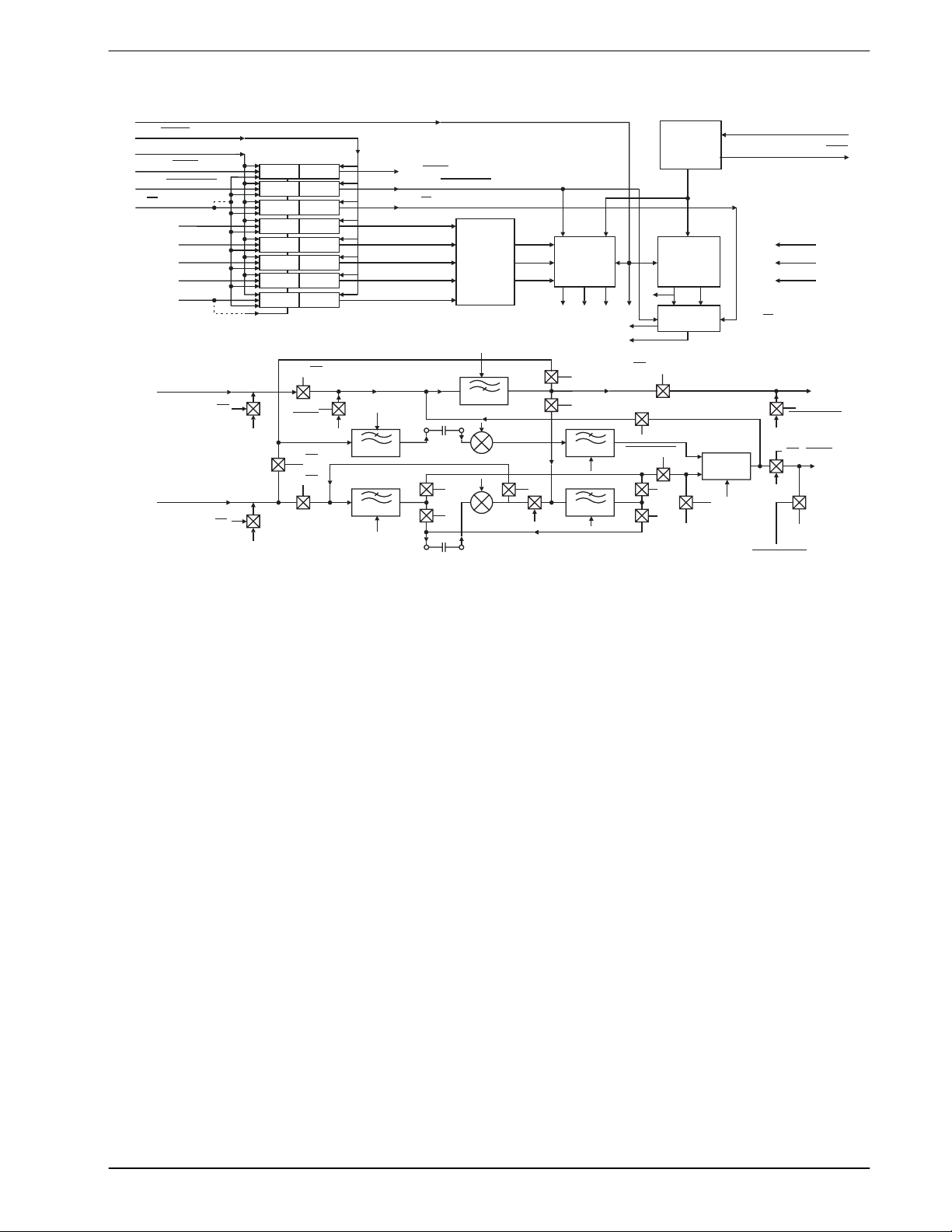
The MX214/224 Variable Split Band Inverters are designed for mobile and cellular radio voice security
applications. Digital control functions are loaded serially into the MX214. The MX224 is loaded in parallel.
The MX214/224 ICs include a highpass filter that rejects subaudio frequencies, ensuring full CTCSS
compatibility. This CTCSS filter is not included on the earlier generation MX204 VSB Inverter.
The MX214/224 splits the voiceband (300-2700Hz) into upper and lower subbands, and inverts each subband
about itself. The ‘split point’ (defined as the frequency where the voice band is subdivided), is externally
programmable to 32 distinct values in the 300 to 3000Hz range. In the ‘fixed code’ mode, a single point is
used. Fixed mode operation nets approximately 4 mutually exclusive secure channels.
In ‘rolling code’ mode, the split point is changed many times per second, usually under control of a
microprocessor. Rolling code scrambling requires synchronization, offers higher security than fixed code
operation, and provides a much greater number of mutually exclusive secure channels.
The MX214/224 offers a recovered audio product close to that of a telephone. The on-chip ‘ Mute’ function is
useful when implementing rolling code continuous synchronization schemes. ‘Powersave’ and
‘Clear/Scramble’ controls are also included on-chip. Timing and filter clocks are derived internally from an
on-chip 1MHz reference oscillator driven by a 1MHz crystal or clock pulse input.
The MX214 and the MX224 operate from a single 5.0V supply and available in the following packges:
22-pin CDIP (MX214J/MX224J), 22-pin PDIP (MX214P/MX224P), and 24-pin PLCC (MX214LH/MX224LH).
1998 MX-COM, Inc. www.mxcom.com Tel: 800 638 5577 336 744 5050 Fax: 336 744 5054 Doc. # 20480112.002
4800 Bethania Station Road, Winston-Salem, NC 27105-1201 USA All trademarks and service marks are held by their respective companies.
Page 2

Variable Split Band Inverter 2 MX214/224
Contents
Section Page
1. Block Diagram................................................................................................................3
2. Signal List.......................................................................................................................4
3. External Components....................................................................................................7
4. General Description.......................................................................................................8
5. Application .....................................................................................................................9
5.1 Audio Quality.......................................................................................................................... 9
6. Performance Specifications........................................................................................11
6.1 Electrical Specifications........................................................................................................ 11
6.1.1 Absolute Maximum Limits.......................................................................................................11
6.1.2 Operating Limits......................................................................................................................11
6.1.3 Operating Characteristics .......................................................................................................12
6.1.4 Timing.....................................................................................................................................14
6.2 Packages.............................................................................................................................. 15
MX-COM, Inc. reserves the right to change specifications at any time without
notice.
1998 MX-COM, Inc. www.mxcom.com Tel: 800 638 5577 336 744 5050 Fax: 336 744 5054 Doc. # 20480112.002
4800 Bethania Station Road, Winston-Salem, NC 27105-1201 USA All trademarks and service marks are held by their respective companies.
Page 3
Variable Split Band Inverter 3 MX214/224
1. Block Diagram
POWERSA VE
LOAD / LATCH
SERIAL CLOCK
ENABLE / MUTE
CLEAR / SCRAMBLE
Rx / (SER / PAR)Tx
A0
A1
A2
A3
A4
(SERIAL DATA IN)
Rx IN
Tx IN
PS
PS
INPUT LATCHES
BIAS
Tx ⋅ PS
Tx ⋅ PS
BIAS
EN Rx⋅⋅PS
Rx
MUTE
BIAS
CK
3
FILTER 3
CK
A
EN / MUTE
CLEAR / SCRAMBLE
Rx / Tx
ROM
CK
CTCSS
C
5
Rx
Tx
C6
Rx / Tx
4
PS + EN Rx⋅
BIAS
BIAS
XT AL / CLOCK
XT AL
V
DD
V
BIAS
V
SS
Tx OUT
PS + EN Tx⋅
PS MUTE Rx⋅⋅
Rx OUT
BIAS
1MHz
OSC
1MHz
CLOCK
DIVIDER
CK
CK
C2
CK
CK4
4
A
PS
3
SCRAMBLE
FC1F
CK
A
B
Rx
Rx
F
C2
FILTER 4
F
C1
Rx
FILTER 2FILTER 1
Tx
CLOCK
DIVIDER
CLOCK
SWITCHING
PS EN Tx⋅⋅
Tx
Tx
Rx
BIAS
CK
B
CLEAR
CK
B
Σ
CK
Figure 1: Block Diagram
1998 MX-COM, Inc. www.mxcom.com Tel: 800 638 5577 336 744 5050 Fax: 336 744 5054 Doc. # 20480112.002
4800 Bethania Station Road, Winston-Salem, NC 27105-1201 USA All trademarks and service marks are held by their respective companies.
Page 4
Variable Split Band Inverter 4 MX214/224
2. Signal List
MX214
Pin No.
MX224
Pin No.
Signal Name Description
J/P LH J/P LH
7 1 1 1 Xtal/Clock Input to the clock oscillator inverter. A 1MHz crystal
input or externally derived 1MHz clock is injected
here.
822 2
Xtal
Output of the clock oscillator inverter.
9 3 Serial Data Input This pin is used to input an 8-bit word representing
the digital control functions. This word is loaded
using the serial data clock and in input in the
following sequence: MUTE, CLEAR,
A1, A2, A3, A4. The
is operated on the
Latch/Load
Tx/Rx , A0,
completion. Reference the timing diagram in Figure
8.
3 – A4
4 – A3
5 – A2
6 – A1
7 – A0
3 – A4
4 – A3
5 – A2
6 – A1
7 – A0
88
Programming
Inputs
Tx/Rx
In parallel mode, these five digital inputs define the
split point frequency. Each of the 5 input pins has a
1M internal pull-up resistor. See Table 4 for
programming information.
This digital input selects the Receive and Transmit
paths and configures upperband and lowerband
filter bandwidths while setting the CTCSS highpass
filter position on the signal path. See Table 2,
Figure 6, and Figure 7. 1M internal pull-up resistor
(Rx).
13 8
Serial/Parallel
This pin must be connected to V
for serial loading.
SS
Internal 1M pull-up resistor.
9 9 Clear/Scramble This digital input puts the device into ‘Clear’ or
‘Scramble’ mode by controlling the application of
carrier frequency to the Upper and Lower band
balanced modulators. In ‘Scramble’ mode, the
balanced modulator carrier frequency values are
selected by the split point address A0-A4. See
Table 4. In ‘Clear’ mode, the carriers are disabled
and the balanced modulators are bypassed
internally, i.e. the lower band signal is not added to
the output signal. 1MHz internal pull-up resistor
(Clear).
10 10 Enable/Mute This digital function is used to disable the Receive or
the Transmit signal paths for rolling code
synchronization while maintaining bias conditions.
Synchronization data can be transmitted during the
Mute periods, as is done in the MX1204 VSB
Scrambler Module. 1M Internal pull-up resistor
(Enable)
14 10 Serial Clock
Input
This is the externally applied data clock frequency
used to shift input data along in devices wired in the
Serial-loading mode. One full data clock cycle is
required to shift one data bit completely into the
register. See Timing Diagram Figure 8. 1M
Internal pull-up resistor.
1998 MX-COM, Inc. www.mxcom.com Tel: 800 638 5577 336 744 5050 Fax: 336 744 5054 Doc. # 20480112.002
4800 Bethania Station Road, Winston-Salem, NC 27105-1201 USA All trademarks and service marks are held by their respective companies.
Page 5
Variable Split Band Inverter 5 MX214/224
MX214
Pin No.
MX224
Pin No.
Signal Name Description
J/P LH J/P LH
15 11 11 11
Latch/Load
This pin controls the loading of the 8 digital function
inputs (ENABLE, CLEAR, A0-A4) into the internal
register. When this pin is at a logic ‘1’, all eight
inputs are transparent and new data acts directly.
For controlled changing of parameters in the
parallel,
Latch/Load must be kept at logic ‘0’ while
a new function is loaded, then strobed 0-1-0 to latch
the inputs in. For serial loading, the serial data
should be loaded with the
and then the
Latch/Load strobed 0-1-0 on
Latch/Load at logic ‘0’
completion of data loading. Internal 1M pull-up
resistor (Load). See Figure 8.
16 12 12 12 Powersave This digital input is used to place the MX214/224
into Powersave mode where all parts of the device
except the 1MHz oscillator are shut down. All signal
input and output lines are made open circuit, free of
all bias. This allows signal paths to be routed
externally around the device, while reducing current
consumption. A logic ‘0’ at this input enables the
device to work normally as shown in Table 2.
Internal 1M pull-up resistor.
17 13 13 13 V
SS
Negative supply (GND)
18 14 14 14 Internal connection This pin is internally connected. Leave open circuit.
19 15 15 15 Rx Output This is the processed received audio signal output.
This pin is held at a DC ‘bias’ voltage for all
functions except Powersave. This buffered output is
driven by the summing circuit in the Rx mode.
Signal paths and bias levels are detailed in Table 2
and Figure 7.
20 16 16 16 Tx Output This is the processed audio output for the
transmission channel. This pin is held at a DC ‘bias’
voltage for all functions except Powersave. This
summed and buffered signal is passed through the
CTCSS high pass Filter to the output pin in the Tx
Mode. Signal paths and bias levels are detailed in
Table 2 and Figure 6.
21 17 17 17 V
BIAS
Normally at VDD/2, this pin requires an external
decoupling capacitor (C7) to V
SS
.
22 18 18 18 Rx Input This is the analog received signal input. This pin is
held at a DC ‘bias’ voltage by a 300k on-chip bias
resistor, which is selected for all functions except
Powersave. It must be connected to external
circuitry by capacitor C3. See Figure 2 and Figure
3. This input is routed through the CTCSS High
Pass Filter in Rx mode to remove subaudio
frequencies from the voiceband. Signal paths and
bias levels are detailed in Table 2 and Figure 7.
1 19 19 19 Highband Filter
Output
The output of the Input Filter of the Upperband limit.
The
Tx/Rx functions sets the lowpass filter at
3400Hz or 2700Hz respectively. This output must
be connected to the Highband Balanced modulator
input via capacitor C5. See Figure 2 and Figure 3.
1998 MX-COM, Inc. www.mxcom.com Tel: 800 638 5577 336 744 5050 Fax: 336 744 5054 Doc. # 20480112.002
4800 Bethania Station Road, Winston-Salem, NC 27105-1201 USA All trademarks and service marks are held by their respective companies.
Page 6

Variable Split Band Inverter 6 MX214/224
MX214
Pin No.
MX224
Pin No.
Signal Name Description
J/P LH J/P LH
2 20 20 20 Highband Balanced
Modulator Input
The input to the Balanced Modulator of the
Upperband limit. This input must be connected to
the Highband Filter Output via capacitor C5. See
Figure 2 and Figure 3.
3 21 21 21 Lowband Balanced
Modulator Input
The input to the Balanced Modulator of the
Lowerband limit. This input must be connected to
the Lowband Filter Output via capacitor C6. See
Figure 2 and Figure 3.
4 22 22 22 Tx input This analog ‘Clear’ audio input for the VSB
Scrambler. This pin is held at a DC ‘bias’ voltage by
a 300k on-chip bias resistor, which is selected for
all functions except powersave. In must be
connected to external circuitry by capacitor C4. See
Figure 2 and Figure 3. This input, in Tx mode, is
connected to Upper and Lowerband input filters.
Signal paths and bias levels are detailed in Table 2
and Figure 6.
5 23 23 23 Lowband Filter
Output
The output of the Input filter of the lowerband limit.
The
Tx/Rx function determines which filter is used
(Filter 1 or 2). See Figure 6 and Figure 7. This
output must be connected to the Lowband balanced
modulator input via capacitor C6. See Figure 7.
6242424V
10,
11,
4, 5, 6,
7, 9
DD
N/C No Connection
A single 5.0V supply is required.
12
Table 1: Signal List
TxRx/ = 1 TxRx/ = 0
MUTE = 0 POWERSAVE
Rx Path Enabled Disabled Disabled Disabled
Rx Out Level Bias Bias Bias High Impedance
Tx Path Disabled Enabled Disabled Disabled
Tx Out Level Bias Bias Bias High impedance
Table 2: Functions Influencing Signal Paths
1998 MX-COM, Inc. www.mxcom.com Tel: 800 638 5577 336 744 5050 Fax: 336 744 5054 Doc. # 20480112.002
4800 Bethania Station Road, Winston-Salem, NC 27105-1201 USA All trademarks and service marks are held by their respective companies.
Page 7

Variable Split Band Inverter 7 MX214/224
3. External Components
V
DD
X1
R2
C1C2
V
Xtal/Clock
R1
Xtal
SS
C4
C5
C6
Tx IN
V
DD
Xtal/Clock
Xtal
Serial Data In
N/C
N/C
1
(19)
2
(20)
3
(21)
4
(22)
(23)
5
(24)
6
(1)
7
(2)
8
9
(3)
(18)
(17)
(16)
(15)
(14)
(13)
(12)
(11)
(10)
10
11
MX214P, MX214J
(MX214LH)
(8)
22
21
20
19
18
17
16
15
14
13
12
Rx IN
V
BIAS
Tx OUT
Rx OUT
N/C
V
SS
Around Through
Load/Latch
Serial Clock In
Parallel/Serial
N/C
Figure 2: Recommended External Components ‘MX214 Serial Loading’
C3
C7
C8
V
SS
X1
V
DD
24
23
22
21
20
19
18
17
16
15
14
13
V
DD
Tx IN
Rx IN
V
BIAS
Tx OUT
Rx OUT
N/C
V
SS
C6
R2
C1C2
V
Xtal/Clock
R1
Xtal
SS
Programming
Inputs
Clear/Scramble
Around/Through
Xtal/Clock
Xtal
A4
A3
A2
A1
A0
Rx/Tx
Enable/Mute
Load/Latch
1
2
3
4
5
6
7
8
9
10
11
12
MX224P, MX224J
(MX224LH)
Figure 3: Recommended External Components 'MX224 Parallel Loading'
C5
C4
C3
C8
C7
1998 MX-COM, Inc. www.mxcom.com Tel: 800 638 5577 336 744 5050 Fax: 336 744 5054 Doc. # 20480112.002
4800 Bethania Station Road, Winston-Salem, NC 27105-1201 USA All trademarks and service marks are held by their respective companies.
Page 8

Variable Split Band Inverter 8 MX214/224
Component Notes Value Tolerance
R1
1.0M
±10%
R2 Selectable
C1 33pF ±20%
C2 68pF ±20%
C3 15nF ±20%
C4 15nF ±20%
C5 1 1.0µF ±20%
C6 1 1.0µF ±20%
C7 1.0µF ±20%
C8 1.0µF ±20%
X1 2 1MHz
Table 3: Recommended External Components
Notes:
1. C5 and C6 are coupling capacitors between filter outputs and balanced modulator inputs.
2. For best results, a crystal oscillator design should drive the clock inverter input with signal levels of at
least 40% of V
, peak to peak. Tuning fork crystals generally cannot meet this requirement. To
DD
obtain crystal oscillator design assistance, consult your crystal manufacturer.
4. General Description
The MX214/224 Variable Split Band Inverters are designed for mobile and cellular radio voice security
applications. Digital control functions are loaded serially into the MX214. The MX224 is loaded in parallel.
The MX214/224 ICs include a highpass filter that rejects subaudio frequencies, ensuring full CTCSS
compatibility. This CTCSS filter is not included on the earlier generation MX204 VSB Inverter.
The MX214/224 splits the voiceband (300-2700Hz) into upper and lower subbands, and inverts each subband
about itself. The ‘split point’ (defined as the frequency where the voice band is subdivided), is externally
programmable to 32 distinct values in the 300 to 3000Hz range. In the ‘fixed code’ mode, a single point is
used. Fixed mode operation nets approximately 4 mutually exclusive secure channels.
In ‘rolling code’ mode, the split point is changed many times per second, usually under control of a
microprocessor. Rolling code scrambling requires synchronization, offers higher security than fixed code
operation, and provides a much greater number of mutually exclusive secure channels.
The MX214/224 offers a recovered audio product close to that of a telephone. The on-chip ‘ Mute’ function is
useful when implementing rolling code continuous synchronization schemes. ‘Powersave’ and
‘Clear/Scramble’ controls are also included on-chip. Timing and filter clocks are derived internally from an
on-chip 1MHz reference oscillator driven by a 1MHz crystal or clock pulse input.
1998 MX-COM, Inc. www.mxcom.com Tel: 800 638 5577 336 744 5050 Fax: 336 744 5054 Doc. # 20480112.002
4800 Bethania Station Road, Winston-Salem, NC 27105-1201 USA All trademarks and service marks are held by their respective companies.
Page 9

Variable Split Band Inverter 9 MX214/224
5. Application
The MX214 represents both the MX214 and the MX224 throughout this section.
Recommended external components are shown in Figure 2 and Figure 3. In ‘Scramble’ mode, split point
frequencies are selected and set in accordance with the ROM address code present at the inputs A0-A4. See
Table 4. In ‘Clear’ mode, both upper and Lowerband filter limits are used (see Figure 6 and Figure 7), the
carrier frequencies are turned off, and the balanced modulators are bypassed internally. The Lowband audio
is removed from the output signal prior to summing.
ROM
Address
A4-A0
00000 2800 3105 6172 10000 1135 1436 4504
00001 2625 2923 6024 10001 1050 1351 4424
00010 2470 2777 5813 10010 976 1278 4347
00011 2333 2631 5681 10011 913 1213 4310
00100 2210 2512 5555 10100 857 1157 4273
00101 2100 2403 5494 10101 792 1094 4166
00110 2000 2304 5376 10110 736 1037 4132
00111 1909 2212 5263 10111 688 988 4065
01000 1826 2127 5208 11000 636 936 4032
01001 1750 2049 5102 11001 591 891 3968
01010 1680 1984 5050 11010 552 853 3937
01011 1555 1858 4950 11011 512 813 3906
01100 1448 1748 4807 11100 471 772 3846
01101 1354 1655 4716 11101 428 728 3816
01110 1272 1572 4629 11110 388 688 3787
01111 1200 1501 4587 11111 350 650 3731
Split Point
Hz
Low Band
Carrier, Hz
f
C1
High Band
Carrier, Hz
f
C2
ROM
Address
A4-A0
Split Point
Hz
Low Band
Carrier, Hz
f
C1
High Band
Carrier, Hz
f
C2
Table 4: ROM Address Programming
The MUTE function disables the MX214/224’s audio outputs to allow periodic transmission of synchronization
data. A logic ‘0’ at this input isolates the device while leaving the audio input and output ins at bias level (See
Table 2). When the MX21/224 is in Powersave mode, audio signals may be hardwired around the device
since the input and output pins are open circuit. See Table 2.
5.1 Audio Quality
Figure 4 shows the recommended basic audio system layout using pre- and de-emphasis circuitry to maintain
good recovered speech quality. The Transmit mode,
Do Not
In the Receive mode, de-emphasis should be used after the MX214.
Amplitude
Control
(Optional)
Pre-emphasis MX214 Tx Rx MX214 De-emphasis
Flat Amplitude
Channel
300-3400Hz
Frequency
Inverter
Figure 4: Recommended Basic Communication Audio System Layout
Figure 5 shows the recommended basic audio system layout if it is necessary to install the MX214 within a
radio having pre- and de-emphasis circuitry as a standard. This is where post-emphasis access is not
possible in the transmitter.
pre-emphasize the audio output of the MX214.
Amplitude
Control
Frequency
Inverter
(Optional)
1998 MX-COM, Inc. www.mxcom.com Tel: 800 638 5577 336 744 5050 Fax: 336 744 5054 Doc. # 20480112.002
4800 Bethania Station Road, Winston-Salem, NC 27105-1201 USA All trademarks and service marks are held by their respective companies.
Page 10

Variable Split Band Inverter 10 MX214/224
Amplitude
Pre-emphasis MX214 Tx Rx MX214 De-emphasis
De-emphasis
Pre-emphasis
Control
Flat Amplitude
Channel
300-3400Hz
(Additional)
Frequency
Inverter
(Additional)
(Fitted)
Frequency
Inverter
(Optional)(Fitted)
Figure 5: Recommended Basic Radio Communication Audio System Layout.
During the Transmit function the low pass and CTCSS filters are configured automatically as shown in Figure
6, with cut-off frequencies (-3dB) indicated.
F
CK
3
C
C2
5
CK
3
CK
B
CTCSS
300Hz
PS + ENABLE Tx⋅
Tx OUT
BIAS
Tx IN
BIAS
CK
Σ
CLEAR
4
FILTER 4
3400Hz
2700Hz
PS
BIAS
2900Hz
2900Hz
FILTER 1
CK
A
CLEAR
SCRAMBLE
SCRAMBLE
CLEAR
C
6
F
C1
FILTER 3
3400Hz
3400Hz
2600Hz
2600Hz
FILTER 2
CK
A
SCRAMBLE
Figure 6: Basic Tx Path
During the Receive function the Low Pass and CTCSS filters are configured automatically as shown in Figure
7, with cut-off frequencies (-3dB) indicated.
F
Rx IN
PS
BIAS
BIAS
CK
B
CTCSS
300Hz
Rx ⋅ MUTE
CK
3
FILTER 3
3400Hz
3400Hz
2600Hz
2600Hz
FILTER 2
CK
A
C
5
CLEAR
SCRAMBLE
SCRAMBLE
CLEAR
C
6
C2
F
C1
CK
4
FILTER 4
3400Hz
2700Hz
2900Hz
2900Hz
FILTER 1
CK
A
BIAS
SCRAMBLE
CK
4
Σ
PS + ENABLE Tx⋅
CLEAR
Rx OUT
BIAS
Figure 7: Basic Rx Path
1998 MX-COM, Inc. www.mxcom.com Tel: 800 638 5577 336 744 5050 Fax: 336 744 5054 Doc. # 20480112.002
4800 Bethania Station Road, Winston-Salem, NC 27105-1201 USA All trademarks and service marks are held by their respective companies.
Page 11

Variable Split Band Inverter 11 MX214/224
6. Performance Specifications
6.1 Electrical Specifications
6.1.1 Absolute Maximum Limits
Exceeding these maximum ratings can result in damage to the device.
General Notes Min. Typ. Max. Units
Supply (VDD-VSS) -0.3 7.0 V
Voltage on any pin to V
SS
Current
V
DD
V
SS
Any other pin -20 20 mA
P/LH Packages
Total allowable Power dissipation
at T
AMB
= 25C
Derating above 25C
Operating Temperature -30 70
Storage Temperature -40 85
J Package
Total allowable Power dissipation
at T
AMB
= 25C
Derating above 25C
Operating Temperature -30 85
Storage Temperature -55 125
-0.3 VDD + 0.3 V
-30 30 mA
-30 30 mA
800 mW
10
mW/C above 25C
800 mW
10
mW/C above 25C
C
C
C
C
6.1.2 Operating Limits
Correct Operation of the device outside these limits is not implied.
Min. Typ. Max. Units
Supply (VDD-VSS) 4.5 5.0 5.5 V
Operating Temperature (P/LH) -30 70
Operating Temperature (J) -30 85
Xtal Frequency 1.0 MHz
C
C
1998 MX-COM, Inc. www.mxcom.com Tel: 800 638 5577 336 744 5050 Fax: 336 744 5054 Doc. # 20480112.002
4800 Bethania Station Road, Winston-Salem, NC 27105-1201 USA All trademarks and service marks are held by their respective companies.
Page 12

Variable Split Band Inverter 12 MX214/224
6.1.3 Operating Characteristics
For the following conditions unless otherwise specified.
V
= 5.0V @ T
DD
Audio Level 0dB ref. = 775mV
Static Values
Voltage 4.5 5.0 5.5 V
Current
Enabled 8 mA
Powersave 1.2 mA
Analog Input Impedances
Tx/Rx Input (Enabled) 100
Tx/Rx Input (Powersave) 1
Balanced Modulator 40
Analog Output Impedances
Rx Output (Tx Mode) 100
Rx Output (Rx Mode) 2
Rx Output (Powersave) 1
Tx Output (Tx Mode) 2
Tx Output (Rx Mode) 100
Tx Output (Powersave) 1
Input LPF 1
Digital Values
Digital Input Impedance 100
Dynamic Values
Input Logic ‘1’ 3.5 V
Input logic ‘0’ 1.5 V
Xtal/Clock Frequency 1 MHz
Analog Input Level -18 6 dB
Carrier Breakthrough 1 -55 dB
Baseband Breakthrough 1, 2, 3 -33 dB
Filter Clock Breakthrough 1, 2, 3 -50 dB
Output Noise 1, 4 -45 dB
Passband Characteristics
Clear Mode 7
Passband Gain 0 dB
Output Lower 3dB Point (Rx or Tx) 300 Hz
Output Upper 3dB Point (Rx or Tx) 3400 Hz
Scramble-Descramble 5
Received Signal Passband Gain 6 0 dB
Received Signal Lower 3dB Point 400 Hz
Received Signal Upper 3dB Point 2700 Hz
Transmitted Signal Lower 3dB Point 300 Hz
Transmitted Signal Upper 3dB Point 3400 Hz
AMB
= 25C
, Xtal/Clock Frequency = 1.0MHz
RMS
Notes Min. Typ. Max. Units
k
M
k
k
k
M
k
k
M
k
k
1998 MX-COM, Inc. www.mxcom.com Tel: 800 638 5577 336 744 5050 Fax: 336 744 5054 Doc. # 20480112.002
4800 Bethania Station Road, Winston-Salem, NC 27105-1201 USA All trademarks and service marks are held by their respective companies.
Page 13

Variable Split Band Inverter 13 MX214/224
Notes Min. T yp. Max. Units
CTCSS (Highpass Filter)
-3dB Point 300 Hz
Passband gain 0 dB
Stopband Attenuation at f < 250Hz 40 dB
Operating Characteristics Notes:
1. Measured at the output of a single device.
2. Tx Mode.
3. Rx Mode.
4. With input AC short-circuited to V
SS
.
5. Measured at the output of a receiving device in a scrambler-descrambler system with a transmission
channel having a flat amplitude response and a bandwidth of 300Hz to 3400Hz and measured relative
to the input signal at the transmitting device.
6. Excluding split point 150Hz.
7. Measured at the Rx or Tx output pin of a single source.
1998 MX-COM, Inc. www.mxcom.com Tel: 800 638 5577 336 744 5050 Fax: 336 744 5054 Doc. # 20480112.002
4800 Bethania Station Road, Winston-Salem, NC 27105-1201 USA All trademarks and service marks are held by their respective companies.
Page 14

Variable Split Band Inverter 14 MX214/224
6.1.4 Timing
Timing Notes Min. Typ. Max. Units
Serial Mode
t
SMS
t
PWH
t
PWL
t
DS
t
DHS
t
LL
t
LLW
Parallel Mode
t
LLW
t
DSP
t
DHP
Serial Mode Enable Set-Up 250 ns
Serial Clock ‘High’ Pulse Width 250 ns
Serial Clock ‘Low’ Pulse Width 250 ns
Data Set Up Time 150 ns
Data Hold Time 50 ns
Set Up Time
Latch/Load
Latch/Load Pulse Width
Latch/Load Pulse Width
250 ns
150 ns
150 ns
Data Set Up Time 150 ns
Data Hold Time 20 ns
Table 5: Serial and Parallel Timing
PARALLEL / SERIAL
SERIAL
CLOCK
SERIAL
DATA INPUT
LOAD / LATCH
LOAD / LATCH
PARALLEL
DATA INPUTS
t
SMS
t
DS
1st bit
ENABLE
Serial Loading
t
PWH
t
t
DHS
2nd bit
CLEAR
PWL
3rd bit
Rx / Tx
8th bit
A
4
t
LL
t
LLW
Parallel Loading
t
LLW
t
DSP
t
DHP
NOTE: For 'Serial Load' devices the data loading sequence is: - Enable - Clear - Rx/ - A - A - A - A - ATx
01234
Figure 8: Loading Timing Diagram
1998 MX-COM, Inc. www.mxcom.com Tel: 800 638 5577 336 744 5050 Fax: 336 744 5054 Doc. # 20480112.002
4800 Bethania Station Road, Winston-Salem, NC 27105-1201 USA All trademarks and service marks are held by their respective companies.
Page 15

Variable Split Band Inverter 15 MX214/224
6.2 Packages
PackageTolerances
K
H
L
PIN1
A
A
1.060 (26.92)
B
0.376 (9.55)
0.165 (4.19)
B
E1
E
T
C
K1
P
J
J1
F
C
0.466 (11.84)
E
0.408 (10.36) 0.418 (10.62)
E1
F
H
J
J1
0.058 (1.47)
K
0.075 (1.91)
K1
0.115 (2.92)
L
P
0.0098 (0.249)
T
NOTE: All dimensions in inches(mm.)
Angles are in degrees
TYP. MAX.MIN.DIM.
1.080 (27.43)
0.384 (9.75)
0.230 (5.84)
0.515 (13.08)
1.000 (25.40)
0.020 (0.51)
0.018 (0.46)
0.055 (1.40)
0.080 (2.03)
0.080 (2.03)
0.171 (4.34)
0.100 (2.54)
0.0102 (0.259)
Figure 9: 22-pin CDIP Mechanical Outline:
A
B
E1
PIN 1
K
C
H
L
J
J1
P
Figure 10: 22-pin PDIP Mechanical Outline:
Order as part no. MX214J or MX224J
Pac kageTolerances
TYP. MAX.MIN.DIM.
A
E
Y
T
1.080 (27.43)
0.330 (8.38)
B
C
E
0.420 (10.67)
E1
0.390 (9.91) 0.420 (10.67)
H
0.020 (0.51)
J
0.015 (0.38)
J1
0.040 (1.02)
K
L
P
T
0.185 (4.70)
0.066 (1.68)
0.128 (3.25)
0.100 (2.54)
0.010 (0.25)
Y
NOTE : All dimensions in inches (mm.)
Angles are in degrees
Order as part no. MX214P or MX224P
1.100 (27.94)
0.360 (9.14)
0.480 (12.19)
0.045 (1.14)
0.020 (0.51)
0.065 (1.65)
7°
1998 MX-COM, Inc. www.mxcom.com Tel: 800 638 5577 336 744 5050 Fax: 336 744 5054 Doc. # 20480112.002
4800 Bethania Station Road, Winston-Salem, NC 27105-1201 USA All trademarks and service marks are held by their respective companies.
Page 16

Variable Split Band Inverter 16 MX214/224
E
B
C
K
Y
A
D
W
PIN 1
W
T
J
H
P
G
F
Figure 11: 24-pin PLCC Mechanical Outline:
PackageTolerances
A
0.380 (9.61)
B
0.380 (9.61)
0.128 (3.25)
C
0.417 (10.60)
D
0.417 (10.60)
E
F
G
H
J
0.047 (1.19)
K
0.049 (1.24)
P
0.006 (0.152)
T
30°
W
Y
NOTE: All dimensions in inches (mm.)
Angles are in degrees
TYP. MAX.MIN.DIM.
0.409 (10.40)
0.409 (10.40)
0.146 (3.70)
0.435 (11.05)
0.435 (11.05)
0.250 (6.35)
0.250 (6.35)
0.023 (0.58)
0.022 (0.55)0.018 (0.45)
0.048 (1.22)
0.051 (1.30)
0.009 (0.22)
45°
6°
Order as part no. MX214LH or MX224LH
1998 MX-COM, Inc. www.mxcom.com Tel: 800 638 5577 336 744 5050 Fax: 336 744 5054 Doc. # 20480112.002
4800 Bethania Station Road, Winston-Salem, NC 27105-1201 USA All trademarks and service marks are held by their respective companies.
 Loading...